Close
0%
0%

SRAM as replacement for EPROM

A reprogrammable alternative to flash or EPROM for old microcontroller/CPU development.

Similar projects worth following
This project aims to create a convenient pin & signal compatible alternative to 27Cxxx EPROMs, for use with old MCUs and CPUs. Using a low-power SRAM chip and a supercapacitor, you can make a mostly-nonvolitile memory module that can be erased and reprogrammed an infinite number of times, even in-circuit. Once you finalize your code, the module can be traded out for a standard EPROM with no hardware changes.

The module consists of a stack with a socket for the SRAM, some components, and a plug on the bottom that fits EPROM sockets. The 3D aspect of this makes it a bit hard to draw a full schematic, so the labels of the chip/socket are used instead.

Check the screenshot for settings that work with the TL866 burner.

Once the module is programmed, it will retain data until the capacitor drops to about 2V or so. Early tests suggest this will be at least 5 days with no power, but may be a lot more. I'll post my findings about reliability over the coming weeks.

If you look at the datasheets for a 32K SRAM chip and a 32K EPROM, you'll see that the pinouts and data access waveforms are nearly identical. Here are the few things we need to deal with:

- A14 needs to be rerouted from pin 27 of the EPROM plug to pin 1 of the SRAM.

- /CS needs to be pulled up on the SRAM in order to force it into low power mode when unplugged.

- VPP needs to be rerouted from pin 1 on the EPROM plug to pin 27 (/WE) of the SRAM, and the waveform needs to be changed. On EPROM chips, VPP is held at +5V while idle, then jumps to +12.5V when writing a byte to memory. The SRAM chip expects +5V when idle and GND to write.

  • 1 × HM62256BLP-7 or other 32K SRAM Memory ICs / Static RAM (SRAM)
  • 1 × 28 pin IC socket
  • 1 × 28 pin IC plug or pin header
  • 4 × 10K resistor
  • 1 × Any low-frequency NPN transistor

View all 7 components

  • End of test results

    Nicholas Amrich11/05/2015 at 23:18 0 comments

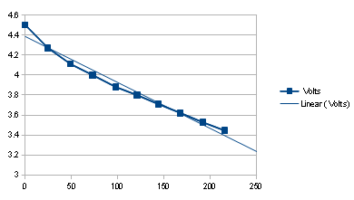
    It works! After a total of 14 days running purely from the capacitor, I have verified the memory contents to be entirely intact. The module was left unplugged on the bench for the duration of the test, with no special attempt to insulate it from RF, magnetic or other noise sources. In fact, it was a few inches away from a display with a noisy power supply, and within about 3 feet of an unshielded 300 watt induction heater. This suggests that the pull up/down resistors used are the right value to protect against noise.

    Here is a final graph of the voltage over time:


  • Initial test results

    Nicholas Amrich10/29/2015 at 13:39 0 comments

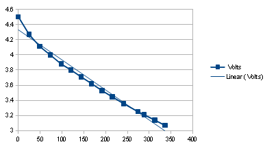
    So far the results are much better than expected, the module has been storing data without external power for over ten days, and is still well above the cutoff voltage. Here is the graph of the voltage over time, with a comparison to a linear drop in voltage:

    It looks like the RAM takes less current to run as the supply voltage drops. Even if the curve does not flatten out any more, the module should retain data for another two weeks, in addition to the ten days it has already run!

    The one caveat here is that I haven't been able to check the memory contents since starting the test. Applying power to the chip to read the RAM would of course recharge the capacitor. So I have no idea if the memory has been corrupted by noise. I will probably wait a few more days before stopping the test to run verification, just to bring the run time up to a nice even two weeks.

View all 2 project logs

Enjoy this project?

Share

Discussions

asorc wrote 04/08/2019 at 16:32 point

Hello, thanks for the project. I found It looking for ways to change an EEPROM, At28c64b-15pu for an sram or RAM ic. Is It possible? I do not care if I have to write each time the program. It's for an educational simple computer, made with 74 ICs.

  Are you sure? yes | no

matseng wrote 01/03/2019 at 14:21 point

I just used this project as inspiration for my CR2032-backed SRAM that's a part of another project.  https://hackaday.io/project/162910-wirez80/log/157797-the-prom-that-wasnt-ee-nor-uv

  Are you sure? yes | no

ComputerCarsten wrote 03/10/2018 at 15:04 point

I HIGHLY RECOMMEND A CAPACITOR BETWEEN BASE AND EMITTER OF THE NPN.

I made a very similar poject today, and your porject was a great help, however pogramming my device went successfull until I try to verify the Content a Second time. Then around 4 to 10 bytes read back BC instread what they are supposed to be. Im sure the cause of this is the Z-diode (~9V) I used instead of leds. My Chinesium MG328 told me it had ~100pF. So when powering up Vpp to 5V that capacitance was enought to cause /WE to go low and trigger some random writes. After adding 1nF between base and emitter that problem was gone!

Hope that Helps someone.

  Are you sure? yes | no

Graham Toal wrote 11/11/2017 at 05:34 point

We used to do almost exactly this on the BBC Micro - except instead of using an external EPROM programmer we'd just attach a flying lead to an available Write pin of the CPU, and we'd use a button cell battery instead of a supercap - held data for years.

  Are you sure? yes | no

Eric Hertz wrote 11/07/2015 at 15:54 point
Wait, do I see that right, you're "programming" the SRAM via an external EEPROM programmer, even using the EEPROM "device" selection? Groovy!

Thought about piggy-backing an EEPROM under it, as well, with a switch to select?

  Are you sure? yes | no

Nicholas Amrich wrote 11/08/2015 at 02:18 point

Yep, you got it!
So with the added EEPROM you could have a 32K block of permanent storage available on the same bus.  I can see that making a lot of sense for doing things like optimization or code base rewrites.  If you need to check how something worked before, you could just click the switch back and have it run the old version with no reprogramming.  Neat idea!

  Are you sure? yes | no

Does this project spark your interest?

Become a member to follow this project and never miss any updates