 Christoph
I wrote test code for both I2C and SPI mode, without luck. The adafruit library also can't communicate with the chip, so I guess I damaged it during soldering. I double-checked the eagle part library, the schematic and the layout and all seem to be good.
All three boards are used now so I redesigned the land pattern a bit and sent another order to OSHPark. The pads I had before seemed to be a bit too wide, so I narrowed them and extended them to the outside. The silk screen had to move to make space for the extended pads, so I just left the corners and a minimal pin 1 indicator.
Here's a comparison:
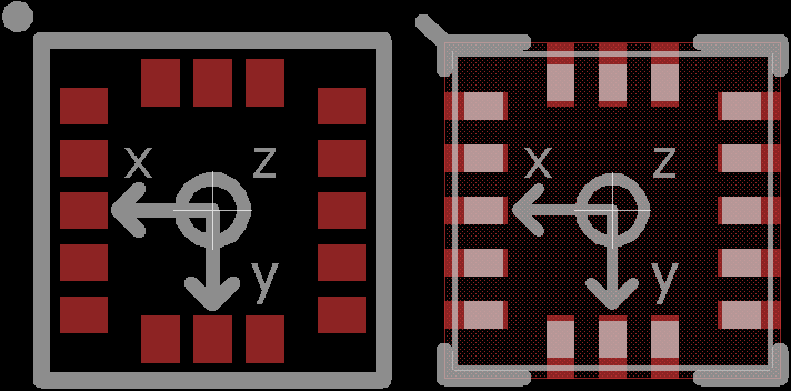
The modified pad geometry should help against solder bridges when soldering in an oven, when I can't poke the chip while the solder is liquid.
Discussions
Become a Hackaday.io Member
Create an account to leave a comment. Already have an account? Log In.
Did you check internal diodes on SDA/SCL pins against GND and VDD? You can also check VDD against GND with DMM on diode test, this should indicate lower voltage drop (cca 300-500mV versus 500-800mV on regular IO pins).
Are you sure? yes | no
SDA and SCL show a voltage drop of 760 mV, but VDD against GND results in an open circuit. Bad...
Are you sure? yes | no
Well, that's bad. Anyway, new board with new footprint is definitely good idea, though I'd leave even longer pads, if you are not space constrained. It definitely helps with this kind of packages.
In the meantime, before new board arrives, I'd also try one more reflow. Those little critters are more sturdy than it may look.
Are you sure? yes | no
I tried again: desoldered the chips from failed attempts, tinned the pads, added flux and placed new chips. One doesn't seem to have any connection at all, one might work in I2C mode because one of the SPI data pins is disconnected. What puzzles me is that the second chip only shows a voltage reading (500 mV) in diode test mode when I connect the positive lead to gnd and the negative to vdd. I think it should be the other way around...
Are you sure? yes | no