 Nigel
Nigel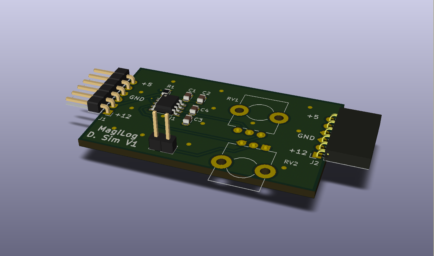
The PCB for the digital input simulator has been done for a bit now. Had some other things that I needed to take care of, so this log got pushed back a few times. I ended up finishing only a day or two after starting, in part to it being a much simpler board than the analog sim. I’ve uploaded the newest round of files to the project page. I should move everything to Github at some point. Perhaps towards the end of the month I’ll have some time to set that up.
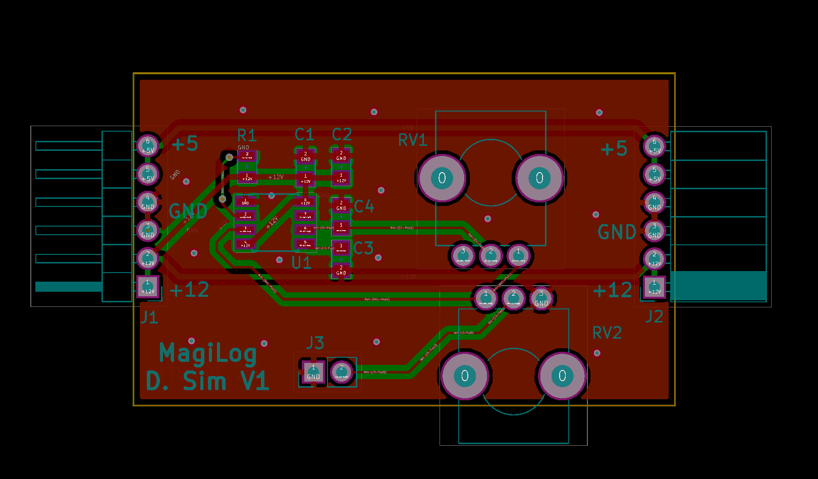
The circuit is based around a single 555 with 2 control pots. One of the pots handles the output frequency, and the other pot handles the amplitude of the pulses. (See older log for more details) This lets us easily adjust the voltage and frequency of the inputs to the FPGA. Using an oscilloscope, I can verify what the FPGA is recording to make sure things are good with the HDL and hardware. The code for the digital module is done, I just need to finish commenting the code as well as the associated project log. There ended up being more details worth discussing than I originally thought so it’s taking a bit of time. Hopefully I’ll have it out in the next few days.
Discussions
Become a Hackaday.io Member
Create an account to leave a comment. Already have an account? Log In.