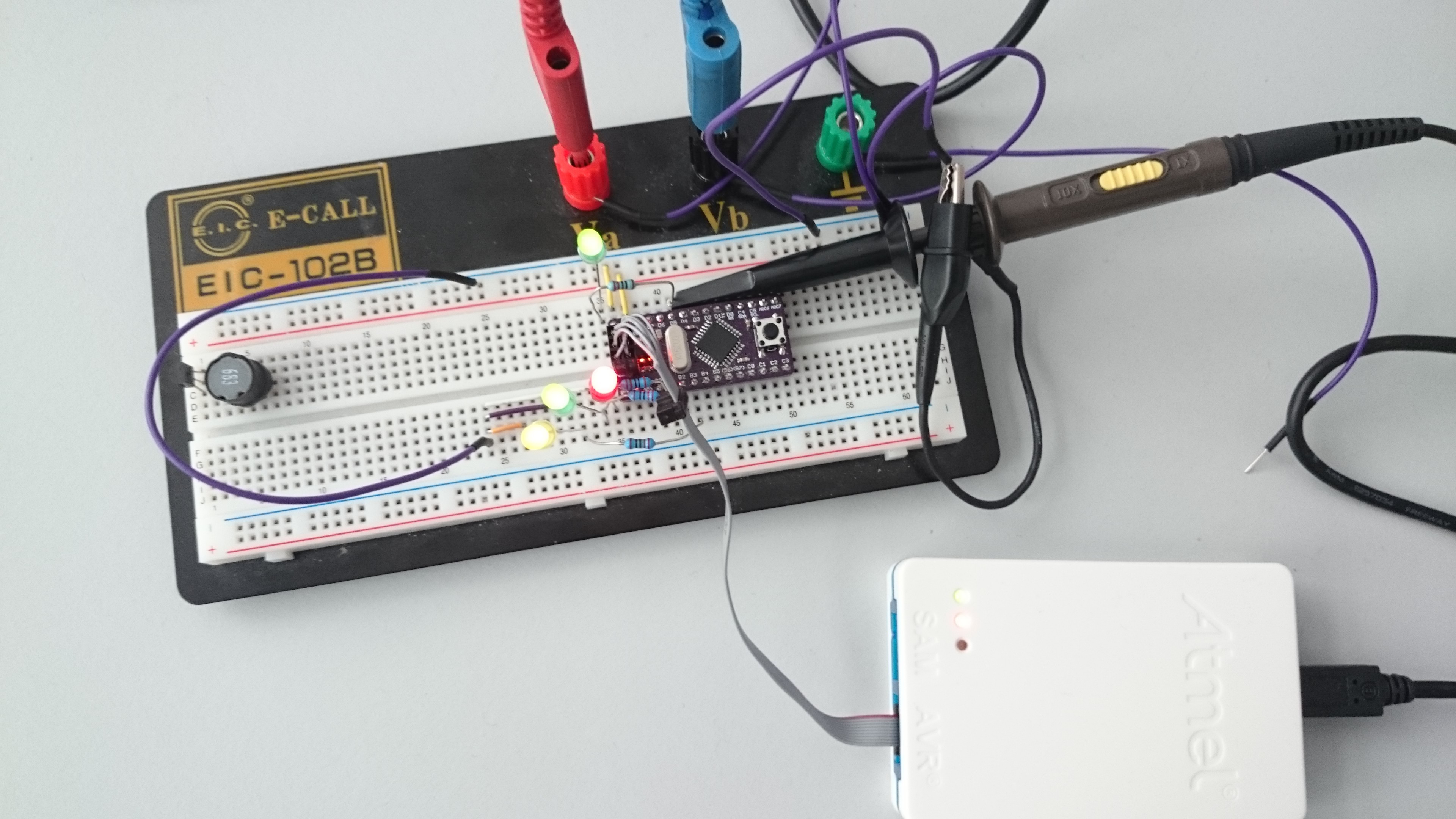
Today I wrote some lines codes for the project and checked the results with an oscilloscope. I created 4 PWM signals, three with the Output Compare Registers of the µC and another one with timer0 by using an ISR. The slowest PWM has 600Hz and the other three have about 30kHz frequency which I want to use for the RGB LEDs.
void ATmega8_PWM_8bit_Software_timer0(uint8_t value)
{
	softpwmvalue=value;
}

void ATmega8_PWM_8bit_Software_timer0_setup(void)
{
	DDRD	|=(1<<PORTD5);		//set D5 as output
	TIMSK	|=(1<<TOIE0);		//Counter0 Overflow Interrupt Enable
	TCCR0	|=(1<<CS00);		//set prescaler to 1
}
ISR(TIMER0_OVF_vect)
{
	static uint8_t counter;
	counter=counter+1;
	if (counter>softpwmvalue)
	{
		PORTD &= ~(1<<PORTD5);			//off
	}
	else
	{
		PORTD |= (1<<PORTD5);			//on
	}

}
Discussions
Become a Hackaday.io Member
Create an account to leave a comment. Already have an account? Log In.