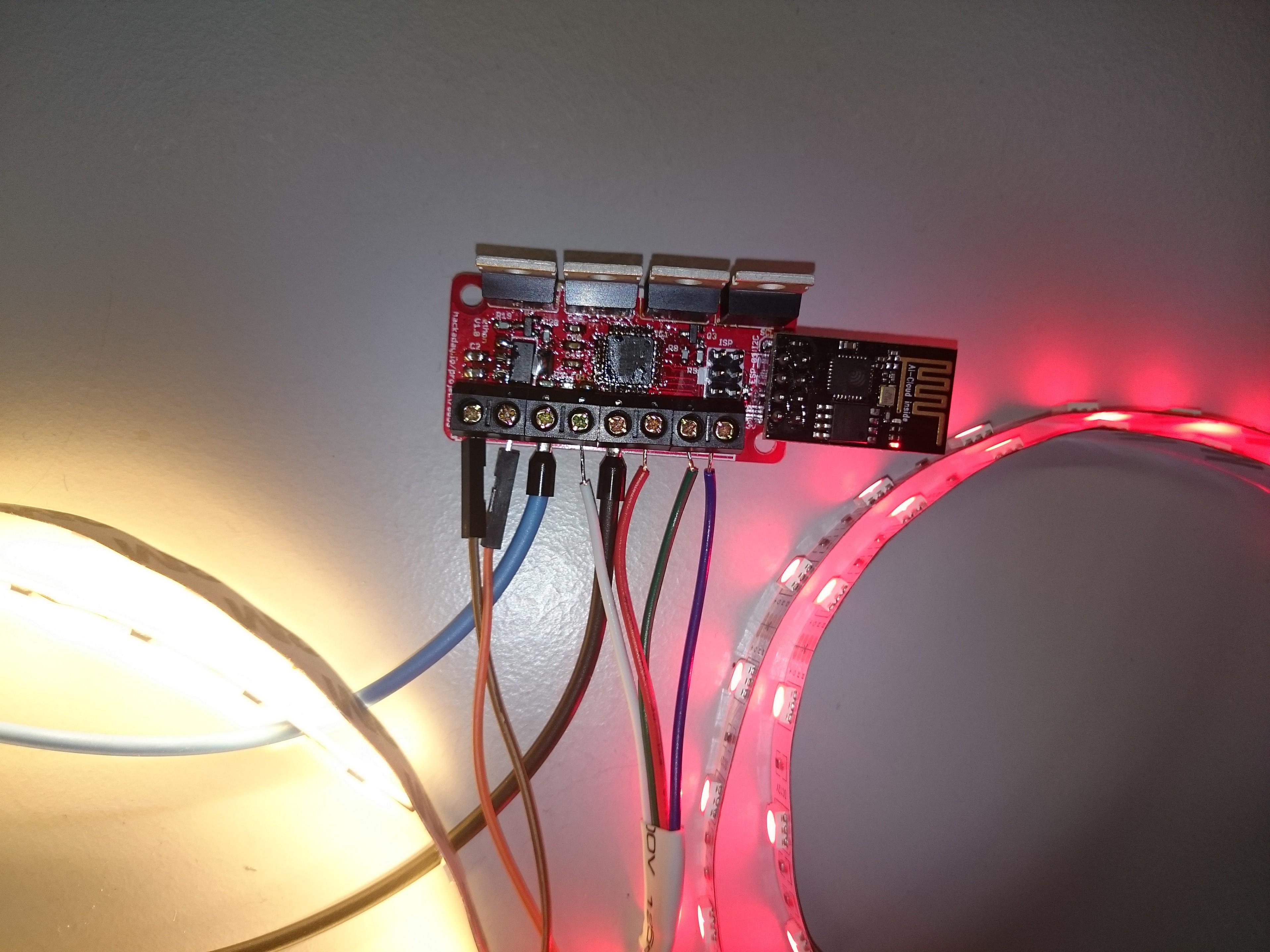
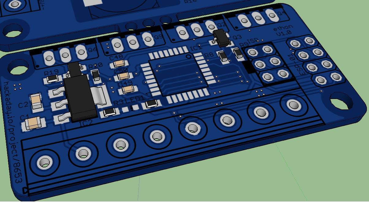
This dimmer is designed for 12V led strips (anode common). The max output current of each color channal is 3A and the max current of the white channal is about 5A all limited by the size of the pathways of the pcb. The voltage limit is caused by the ldo.
0%
0%
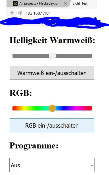
RGB WIFI Dimmer
12V Dimmer with 4-PWM Outputs a 3A and ESP-01 suitable pinheader
Become a Hackaday.io member
Already have an account? Log in.
Just one more thing
To make the experience fit your profile, pick a username and tell us what interests you.
Pick an awesome username
hackaday.io/
Your profile's URL: hackaday.io/username. Max 25 alphanumeric characters.
Pick a few interests
Projects that share your interests
People that share your interests
 Pratik Makwana
 Matthew Sheffield
 Neil Mundt
 Enrico