ajlitt
-
Good news Bad news
01/06/2016 at 06:35 • 12 commentsGood news first: AP mode works with the standard hostapd setup. That means Zero-based routers, WiFi VPN tunnels, honeypots,...
Bad news: If you want your own, you're going to have to make it yourself. FCC type certification is too costly for a niche product like this, even more so when it's already shaping up to be a more expensive board than the Pi itself.
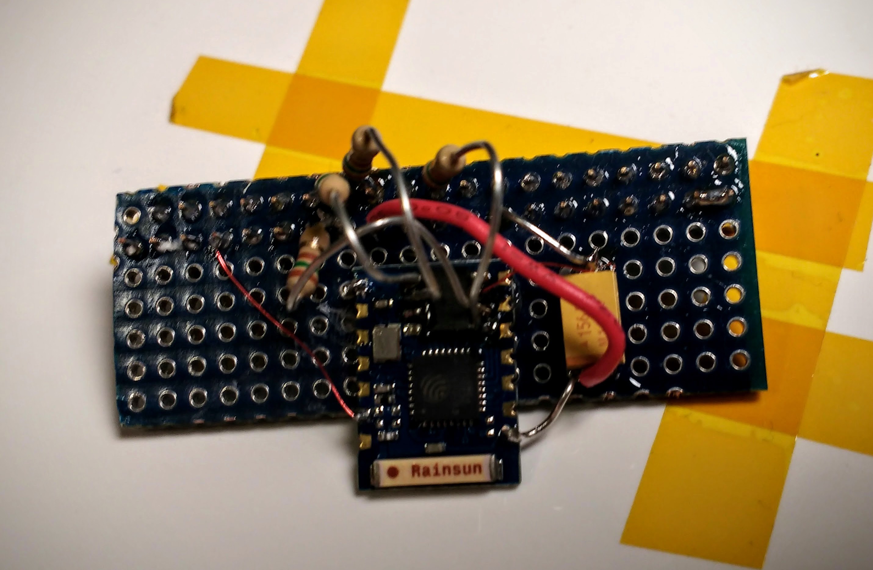
I had a plan to work around this by using the exposed SDIO signals on the FCC approved ESP-12E module. The trick was to force the SPI flash, normally used for the program flash and shared with the SDIO, to stay quiet. This would have had the side effect of forcing the ESP8266 into 1-bit SDIO mode and lowering throughput, but it would make the board easier to assemble and satisfied the FCC. I experimented on an ESP-03, wiring all but the uppert 2 bits of the SDIO bus and forcing the SPI flash's /HOLD signal to ground to keep the flash chip in tristate. In practice, this didn't work:
![]()
It looks messy, but the edges on the SDIO handshake look nice and clean.
Edit after sleeping:
Last night I noticed that the SD_D0 signal had some "toothiness" while high, as if another device were trying to drive the signal. SD_D0 is multiplexed with the DO pin of the SPI flash. The other signals we're hijacking (DI, CLK, /CS) are all inputs to the flash in 1-bit SPI mode. Now that my brain is on right, this suggests that the SPI flash wasn't honoring the /HOLD request. I can think of a few reasons for this, so ignore my doom and gloom.
If this scheme does work, the main side effect would be that SDIO would be reduced to 1 bit mode. Throughput between the Pi and ESP would drop from 200Mbits/s to 50Mbits/s and would become the bottleneck. This is probably a good trade-off: no certifications needed, simpler assembly and BOM, and much better availability in the US of ESP-12E modules vs. bare ESP8266 or ESP8089 parts.
If someone has a hook-up at AI-Thinker, suggest to them that they make an ESP-12E (or -F or whatever) with the SPI flash left unpopulated. That would be ideal.
-
End of year rush
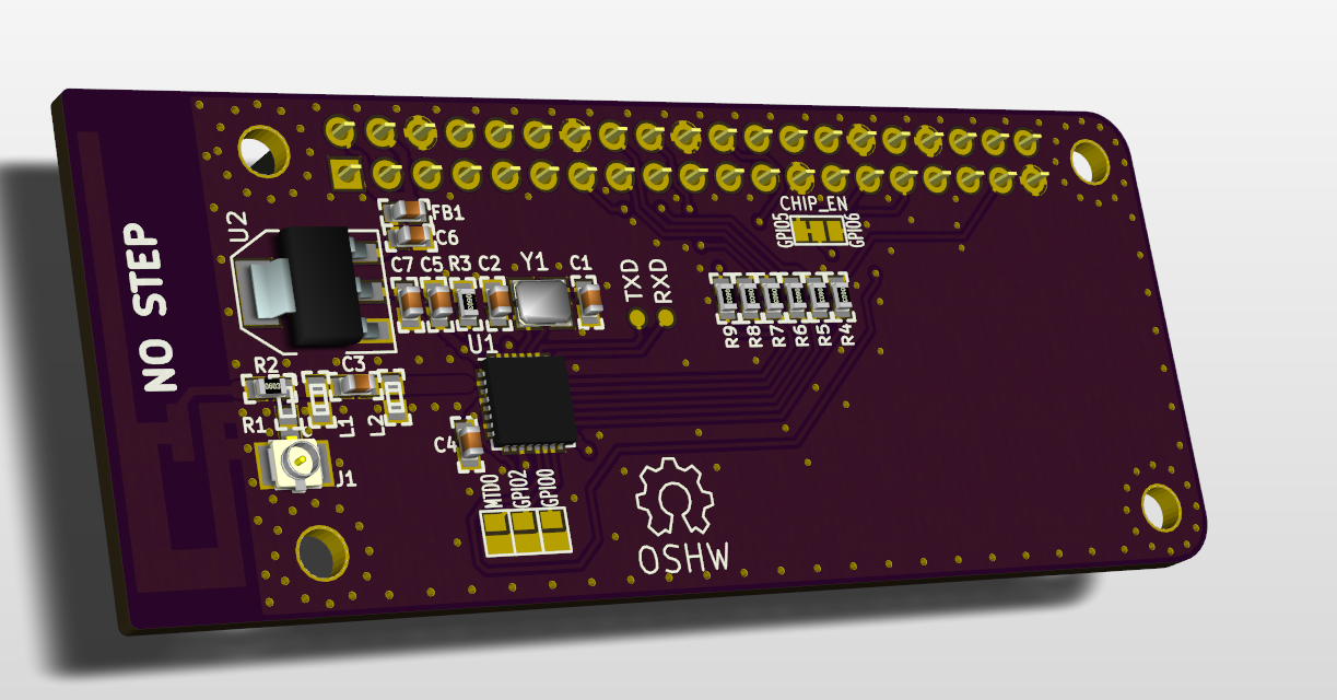
01/01/2016 at 06:52 • 6 commentsV0.2 of the board was committed to Github at Thu Dec 31 23:59:11 2015 -0600. This has some of the routing suggestions from the comments, moves the antenna out past the board edge, fixes the LDO tab short to ground, and removes the HAT EEPROM.
![]()
As long as SDIO is enabled in config.txt, the ESP8266 properly enumerates on the bus and the correct driver is loaded. The expansion header is not much fun if it's only being used for WiFi, and HATs are not allowed to be stackable. So I removed the EEPROM.
That does mean I can't call this a HAT. So I'm looking for a good name that doesn't use "HAT". Any ideas?
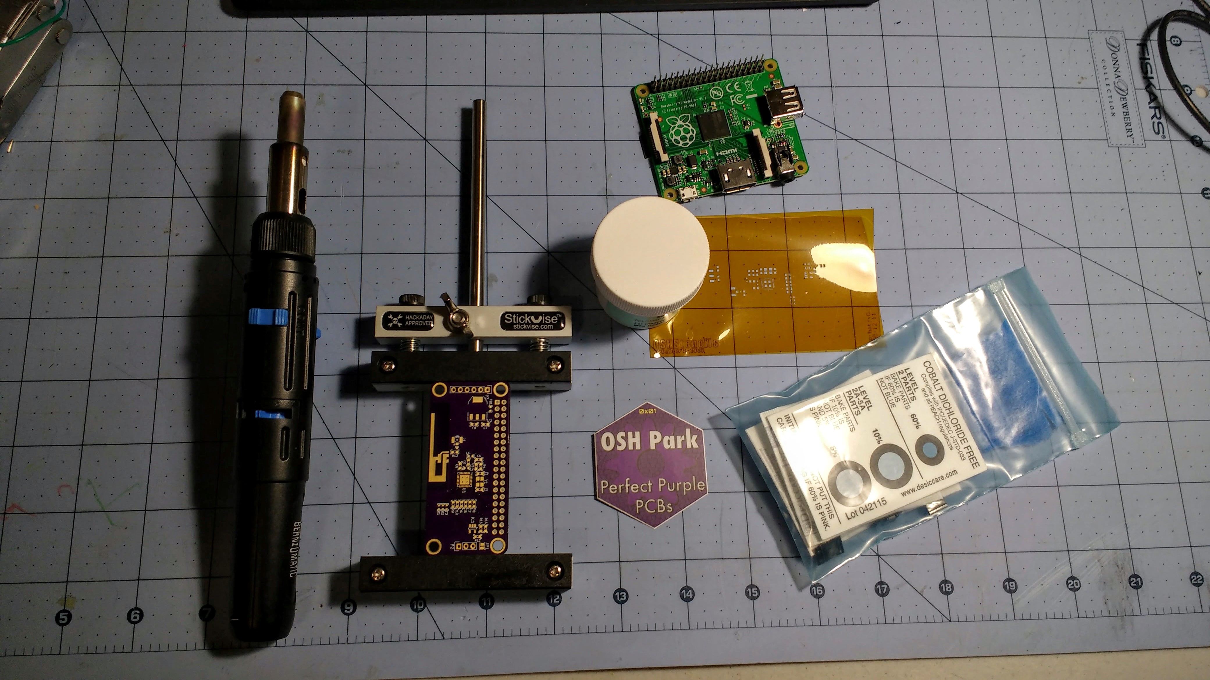
Meanwhile: I reflowed a second board, this time in the toaster. It came out better than the first, and fired up on the first try. The only issue was that the OSH Park white silkscreen turned a bit more yellow than the first hot air hand reflowed board.
Edit: Argh! Some last minute rerouting of the 3.3V behind the chip broke the ground plane under the LNA antenna pin. Probably not going to make a ton of difference, but I haven't sent anything off to manufacture yet.
Edit2: Fixed. I also discovered a no-connect in the RF path, where the DRC error was legit and not due to the antenna weirdness. I added a cut-and-jumper block to change the CH_PD GPIO from GPIO5 to GPIO6 or disconnect CHIP_EN from GPIOs altogether. Finally I redid the solder jumper parts so that there's no paste on top. I'm still holding off on ordering in case I find something else wrong. OSH Park isn't going to be doing anything 'til Monday anyway.
-
Meet v0.1
12/29/2015 at 08:28 • 8 comments![]()
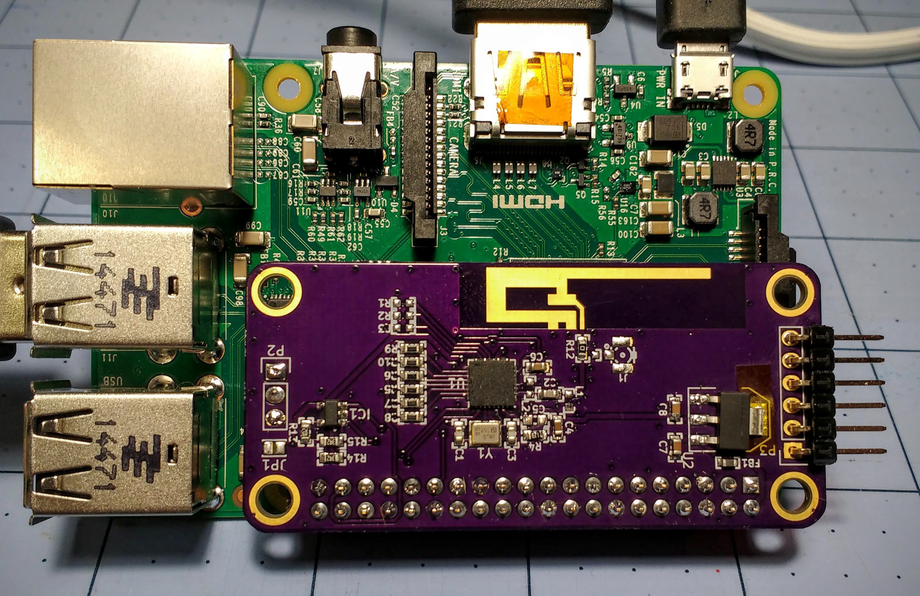
After a long battle trying to find a short on the 3.3V rail, it lives! ~40Mb/s in both directions to the nearby AP, and ~1.5Mb/s up / ~15Mb/s down to the weak AP across the house. That's way better than I expected for my first attempt at RF layout.
I ran into only one flaw in the PCB, and it's one of the classic blunders. I mistakenly routed the tab on the linear regulator to ground. The schematic symbol doesn't define the tab as a separate pin, but the symbol does. This let me get away with routing the tab to ground without angering the DRC. Tab on the AP1117 is Vout, by the way. My mistake cost me a couple of hours where I reflowed the ESP8266 a couple of times thinking the short was underneath.
I decided to use my butane hot air pencil instead of getting out the oven. I'd done this with smaller boards successfully, but this time I had a hard time getting the solder to melt, especially grounded pads and the QFN. The problem seemed to be the bathroom tile I'd been using for a work surface. My theory was that the tile was pulling too much heat from the back of the board, and to stop that loss I put a couple of layers of Kapton tape between the tile and the board as an insulator. This helped greatly, though the unregulated hot air was still tricky to work with.
-
SOON
12/28/2015 at 23:41 • 0 comments![]()
-
Your move, Portland
12/12/2015 at 05:14 • 6 comments![]()
Submitted to OSHPark. Ignore the missing ground pins on the 2 headers, those are an artifact of the renderer.
I took a lot of wild guesses about the RF bits. We'll see if it actually works.
Highlights are an onboard 5V-3.3V LDO to keep from stressing the Pi's 3.3V regulator, pads for an FTDI-style UART header for the Pi's console UART, some stuff for debugging the ESP, onboard antenna, the usual U.FL / 0 ohm resistor setup for switching to an offboard antenna, and of course it's a Pi Zero sized HAT with a config EEPROM.
KiCad design files are on the Github on the main project page.
-
Believe it!
12/11/2015 at 07:39 • 4 comments -
A little faster now
12/10/2015 at 06:35 • 0 commentsI went back to using the router on my bench for testing. I turned down the TX power on the router thinking I was oversaturating the ESP at such a close distance. I switched to channel 6, which is less populated in my neighborhood, and played with orientation of the ESP and the router. Then I cut away more of the perfboard under the antenna. Now I am seeing ~1.5Mb/s upload and ~3.5Mb/s download, with a few runs hitting 4.4Mb/s.
During those runs, the driver on the Pi reports a link quality of 62/70 and -48dBm signal level and a 54Mbit connection. Interestingly enough, OpenWRT on the router shows the TX (to the router) as fluctuating between 22 and 62Mbit/s while RX seems stuck at 2Mbit/s.
While that's still not good performance, it's more evidence that SDIO isn't the bottleneck.
I probed the 3.3V on the ESP-03 module's bypass cap, and there's about 300mVp-p ripple when pushing traffic, which isn't worrisome. While I was poking around I noticed that the ESP-03 has only one cap on 3.3V, while the Espressif guideline is 3 caps: 10uF, 1uF, and 0.1uF. There's not enough room to probe at the chip pads, but I wouldn't be surprised if it's uglier.
I also saw that the antenna signal from the chip goes from the pin to a via, through a couple of right turns, through another via, and doubling back to the pad on the capacitor. I'm no RF guru, but I know enough that I'm not surprised this isn't working well.
-
Have at it
12/08/2015 at 15:04 • 0 commentsMy brain dump is complete, and the driver is in Github. Feel free to play along, and contribute if you like.
I used some snips to carefully cut away the perfboard underneath the antenna, and it does seem to help with the connection across the house to my main AP. I get ~300kbits in iperf, which is terrible, but the 1.5Mbits I was seeing before was with a second AP sitting less than a foot away. Later on I'll try using the AP again, but with WPA turned off to reduce any overhead.
I also hooked the CH_EN signal to a GPIO on the Pi. When I toggle the GPIO off and on, the ES8266 is re-detected on the bus. Next step is to modify the driver to toggle power before attempting to load firmware.
-
I don't know SDIO
12/06/2015 at 19:53 • 0 commentsA quick look with the scope on the SDIO signals shows that CLK is ~50MHz and D0-D3 are active during transfers, so I think we're in 4 bit mode 2, which is good. The edges are a little too round for my liking, so I may try swapping out my series termination resistors (not in the pic, on the back of the PCB) for smaller values.
I don't have indication from the software end that the SDIO bus is running into bad transactions. I'm not sure if I should expect Linux to complain, or if the drivers have error counters that I can see through sysfs or by turning on some debug flag. Unfortunately all three pieces of the puzzle (RPi SDIO, ESP8266 driver, and my janky SDIO bus) are all in question, so it's hard to tell where the fault might be.
Maybe someone at Espressif wants to open their ESP8089 driver SDK?
EDIT: The signals look decent. My probe's compensation was way out of whack.
-
Ugly prototype
12/06/2015 at 15:52 • 0 commentsAfter a week of waiting for parts and a late night of tinkering, I have a Raspberry Pi 2B passing traffic over WiFi through an ESP8266 that thinks it's an ESP8089. My first attempt is ugly: the wiring is fragile, it needs to be power cycled if the driver is unloaded, and the connection is ~1.5Mbits at best, and my failure to keep the perfboard out from under the antenna limits the range greatly.
An FTDI cable (seen in the pics above) is wired to the ESP's UART to monitor the SDIO boot process and (as I discovered) get state info from the firmware. Other than that the only interfaces I used during testing were a USB keyboard and HDMI video.
Todo: look into what SDIO mode we're running in, scope the bus to rule out SI problems, get the modified driver in github, push a small change to the rpi kernel 4.2 branch, document this mess, test on the armv6 build when my Pi A+ gets here (closest to a Zero till the mad rush is over)