 kodera2t
At another project which is making 68008 single board computer, its circuit is simplified by Xilinx XC9536. XC9536 is out-of-production device but still can be got, for example here. (In my case, XC9536 is selected for 68008 board, but generally no need to stick it. Sometimes XC9572 VQG44 has more attractive price, which is pin compatible and doubled programmable elements)
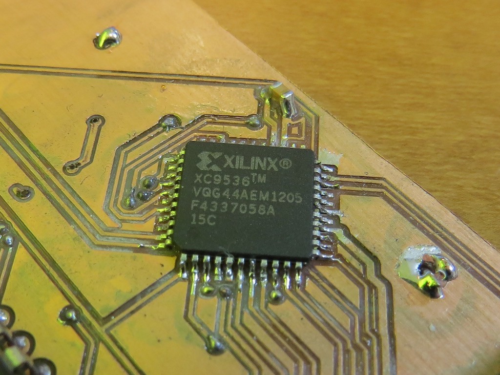
For 68008 board completion purpose, I have obtained ten package of it.
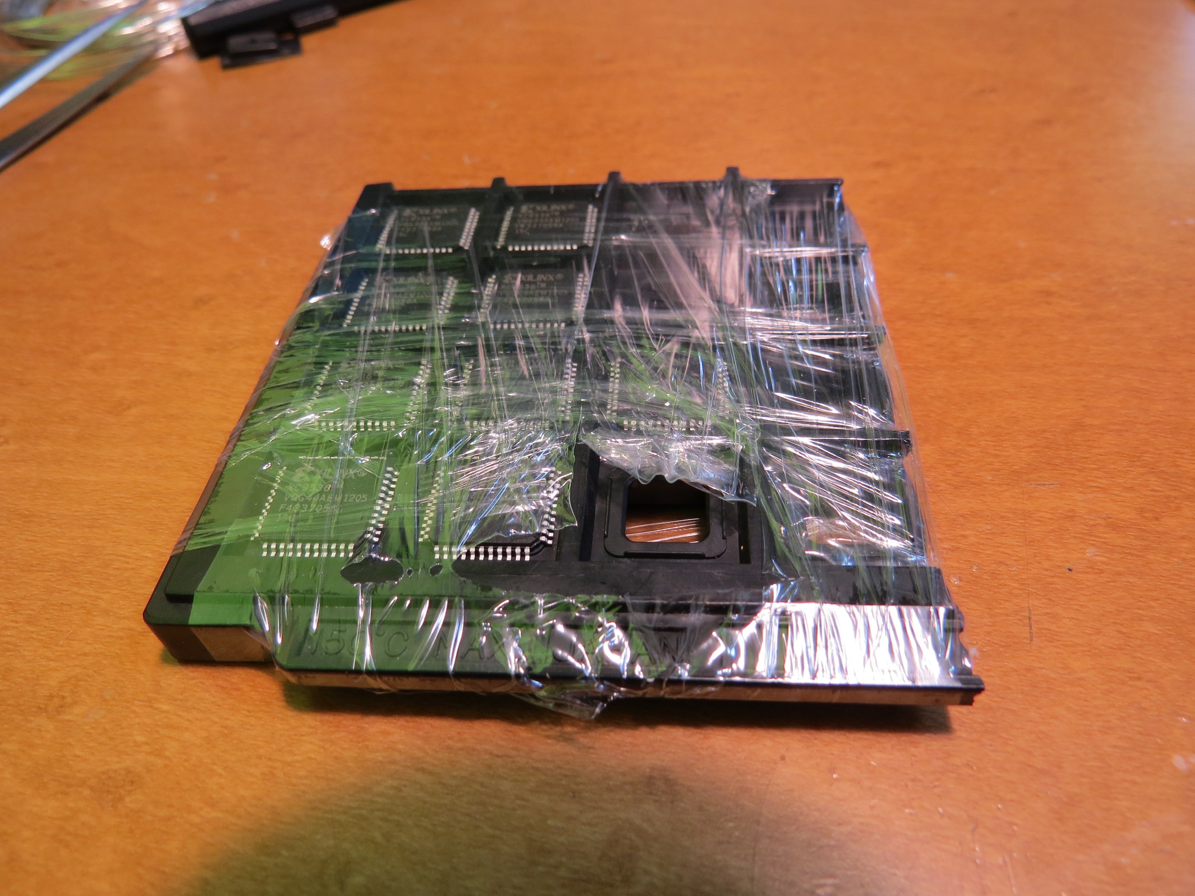
Fortunately I did not have any loss of XC9536 for making 68008, and remaining 9! So I made,
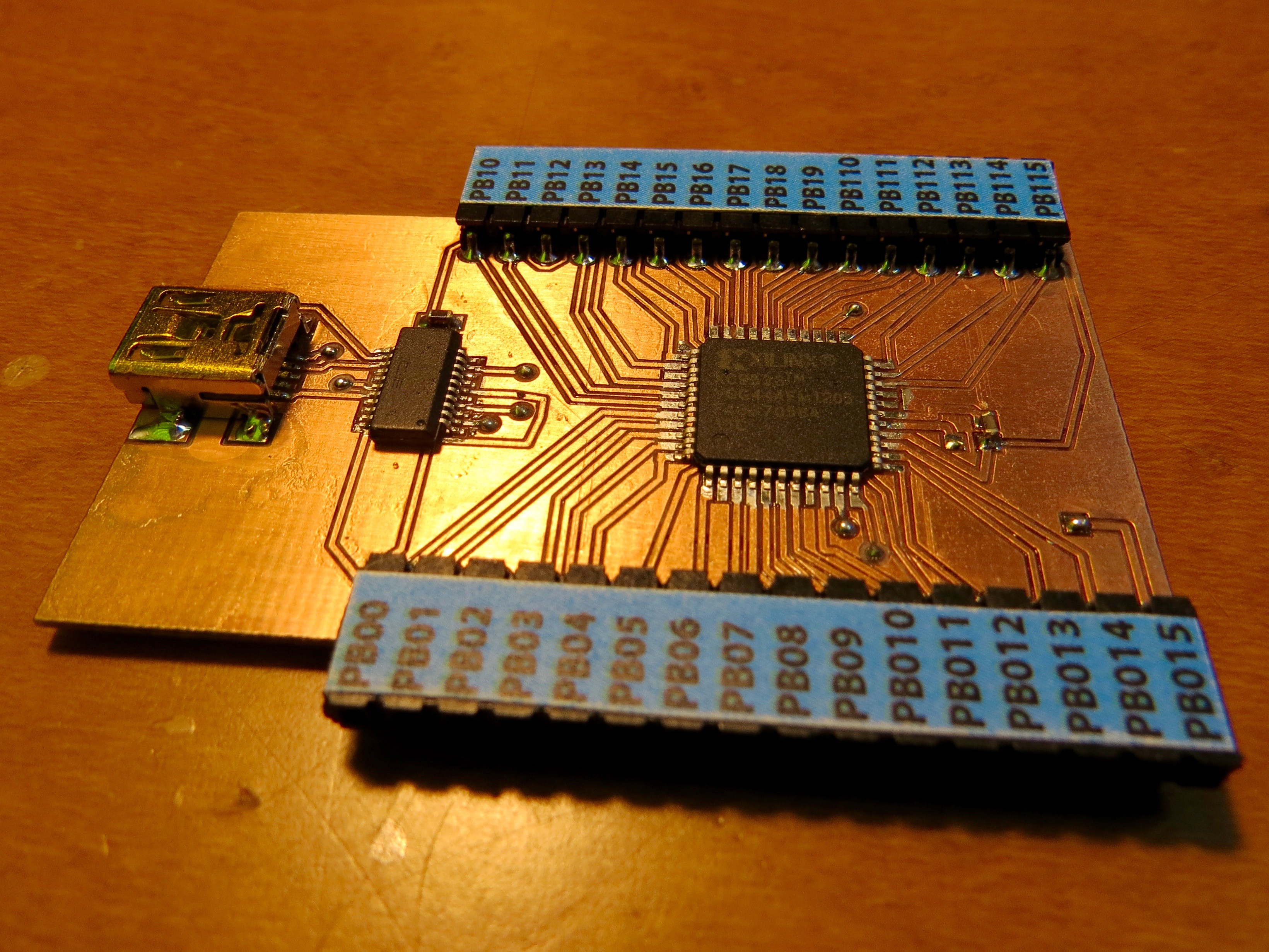
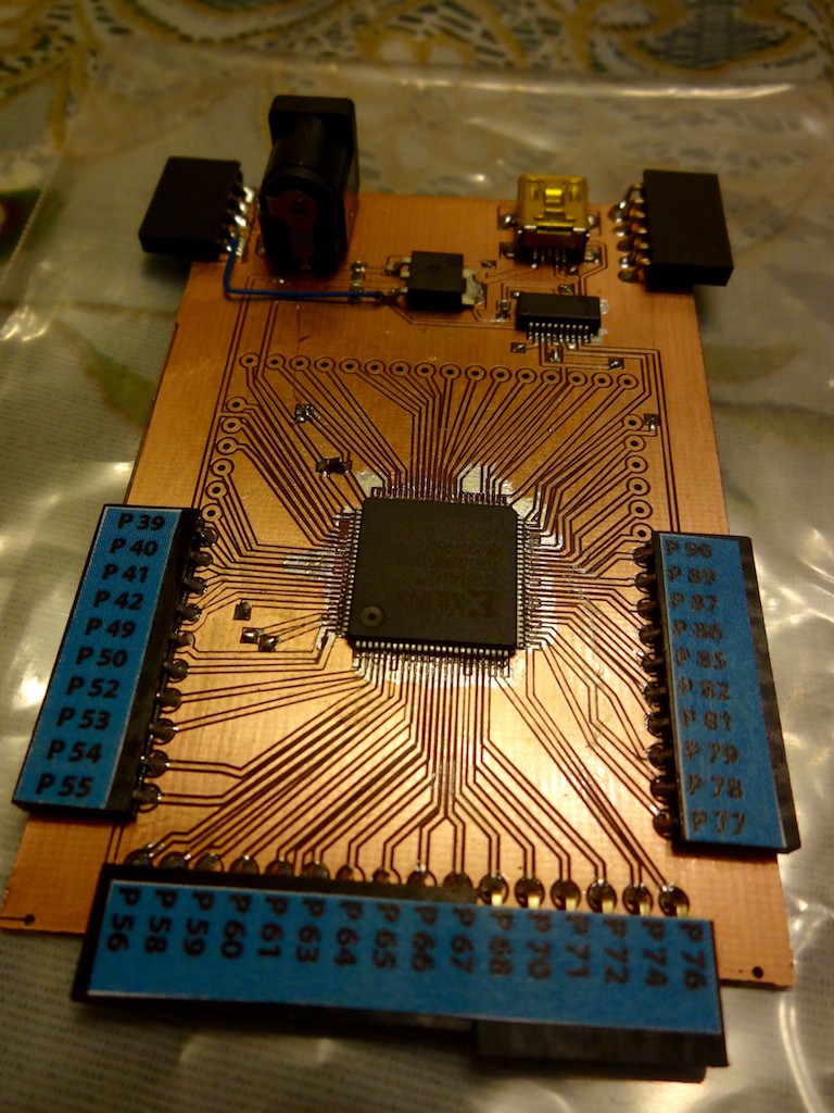
XC9536 simple board capable of .xvf uploading really just for my learning. Indeed, I had a knowledge that some kind of special download hardware (ex. USB blaster?) but found very useful information at one website showing "download by simple FT232RL" !!!
The author also makes USB CPLD programmer and indeed my 68008 was completed by this FT232RL .svf file downloading process.
Here I would explain how to "download" to this board.
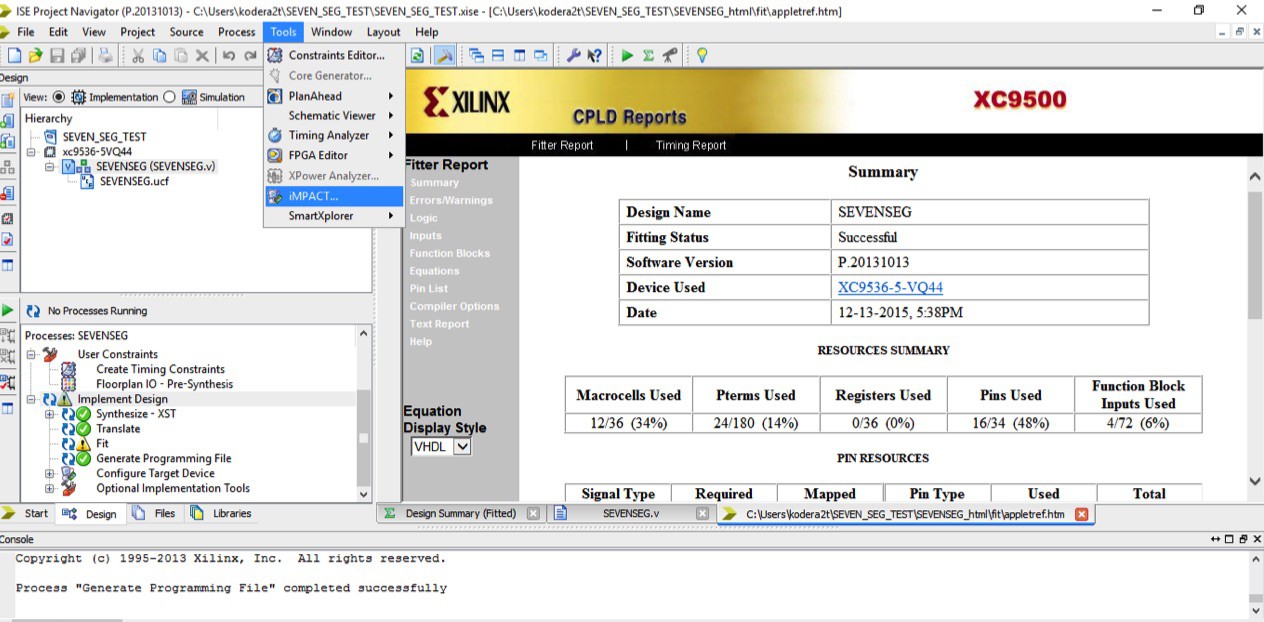
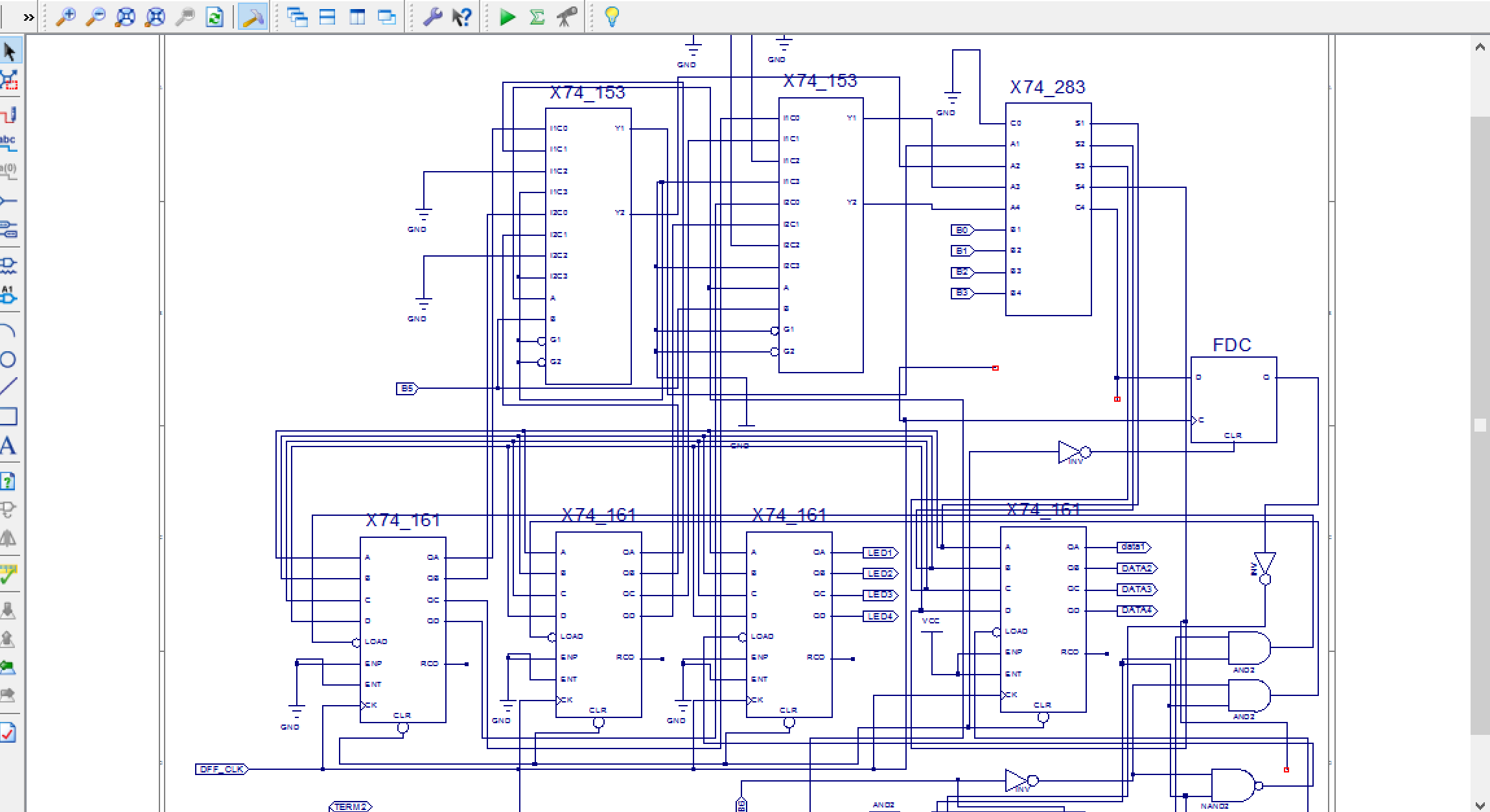
Firstly we can write VHDL or Verilog source byISE Design Suite 14.7. Indeed XC9536 is "ancient" device and up-to-date "Vivado Design Suite" does not support it. ISE Design Suite has some trouble on Windows 10 64bit environment and please find its solution by googling (some "libPortability.dll" problem). After compile success, select "Tools->iMPACT" and
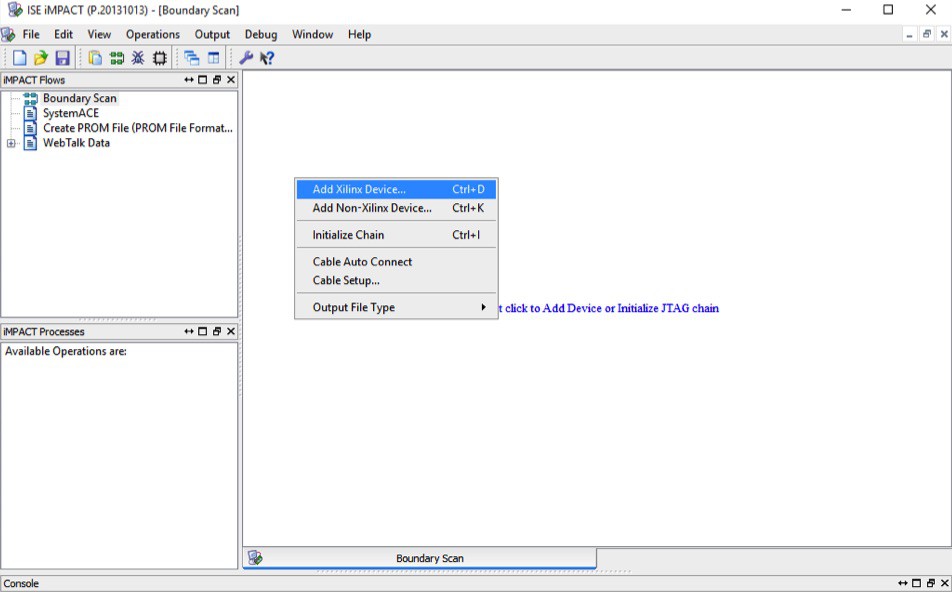
Double click "Boundary Scan" and right click on the right window and select "Add Xilinx Device and select generated .jed file
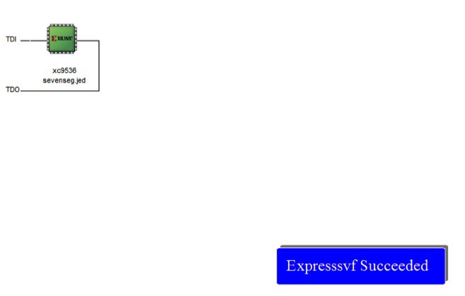
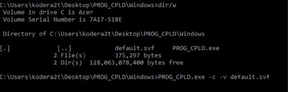
After making .svf file, execute PROG_CPLD.exe which can be found at this website with option -c and -v
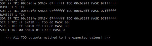
<<< All TDO outputs matched to the expected values! >>>If not, repeat again or check soldering or wiring...
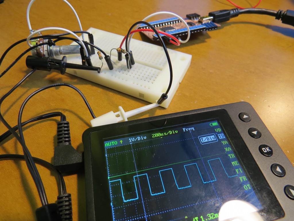
In my case, my CPLD becomes 7-seg driver.
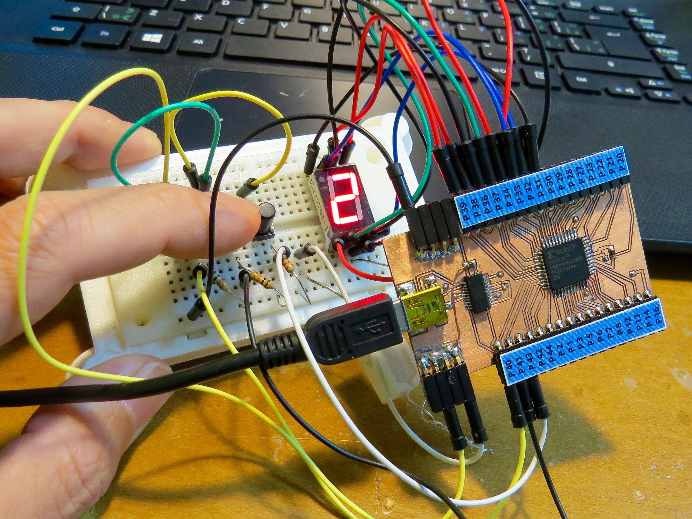
Actual operation (indeed no-worth-to-see) can be found at the following movie.. have fun!


 Skyhawkson
 deftcoyote
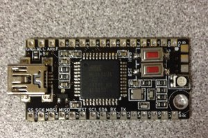
 The Big One
 Hulk
Hulk
Thank you nice follow, K. C. Lee !