 factor
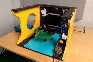
So my son, [B] did the soldering work. His uncle help him mill out the inside of the car to fit the electronics. [B] Drilled the holes for the lights and then painted the car with little sisters help.
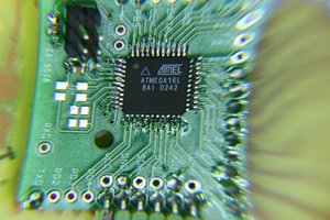
We tested the code on the MSP430 launch pad (see external link).
once the chip was programmed we placed it on the circuit board and put it in the car.
Originally we only planned on lights, but while researching the chips capabilities we figured out that it might be able to drive a piezo speaker. So we quickly cannibalized another device for it's speaker and tested it out.
The push button on top is a locking one, it will arm the car. after the car is armed, once the button is released on the front it will start flashing and wailing.
The idea is that you arm it and then set it on the track. once the lever is released and the cars start down the track the lights will come on.
The front lights are some LEDs I picked up at Walmart after Christmas (replacement bulbs) the top lights are some RGBs that came in a LED kit sold by Radio Shack. The rear lights are just some red LEDs I had around.
Thinks I may have done differently:
Used Resistors on the LEDs.
- The batteries only last about 2 hours (but that is long enough)
- I had to use AAA CR2032 wouldn't drive all the lights.
- found a different way to trigger the lights.
- The front switch was too strong. had to start the lights by hand.
- milled out more of the car.
- It was really tight in the car.
The schematic:

Yes there should be resistors in there ... but it worked for the derby.

 Stefan-Xp
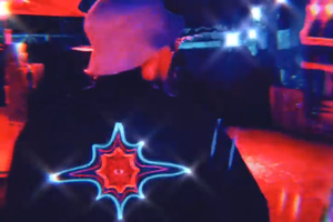
 jayframe
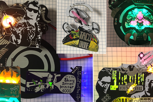
 awkward intelligence
I remember when I was a kid, I loved the pine wood derby. I made one car with taillights and a Lego man driving. This is awesome.