 Kevin Young
-
1Step 1
Order the parts. You can start with ordering only the electronic components and order the other hardware later, if you'd like.
-
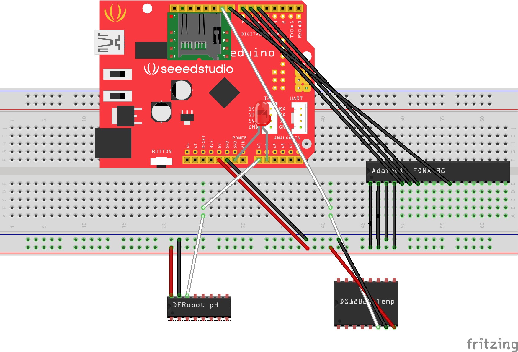
2Step 2
![]()
Use the jumper wires to connect components, as shown in this schematic.
-
3Step 3
Connect the Stalker to the computer via the UART. Ensure that the pins match up on the UART and on the Stalker, otherwise you will get the error: "avrdude stk500_getsync(): not in sync".
-
4Step 4
In the Arduino IDE, be sure to select Board: "Arduino Pro or Pro Mini", and Processor: "ATMega328 (3.3V, 8 MHz)" under the Tools menu. If these setting are not correct you will be unable to communicate with the FONA 3G.
-
5Step 5
Download the Arduino IDE (if you don't have it already), and upload datalogger.ino from the GitHub repo linked on this project page.
-
6Step 6
Solder the temperature sensor. Data sheet: http://cdn.sparkfun.com/datasheets/Sensors/Temp/DS18B20.pdf
-
7Step 7
Solder the P2 and P3 PCB jumper pads on the back of the Stalker. Soldering the P2 enables to turn on and off the power supply of the SD. Soldering the P3 connects RTC/INTA pin to Digital Pin D2(INT0) to allow for sleep/wake via external interrupt. For more info: http://www.seeedstudio.com/wiki/Seeeduino-Stalker_v3#PCB_Jumper_Pads
-
8Step 8
Solder the turbidity sensor. Data sheet: http://www.ge-mcs.com/download/turbidity/920-480B-LR.pdf
-
9Step 9
Finally, upload the sketch to the Stalker by pressing the Upload button. You may have to hold the reset button down immediately before pressing the Upload button, then release it a second or two after pressing the Upload button.
EnviroHub
Solar-powered water quality monitoring with wireless transmission and/or SD card storage capabilities measuring pH, temp, and turbidity.
Discussions
Become a Hackaday.io Member
Create an account to leave a comment. Already have an account? Log In.