0%
0%
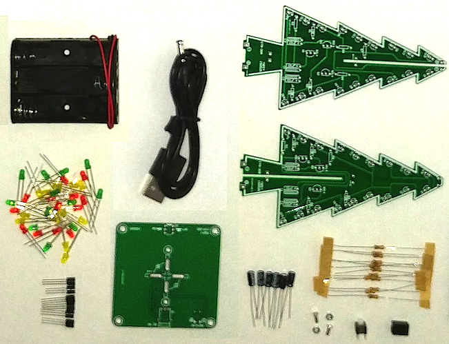
3D LED Christmas Tree
DIY solder kit. The flashing Christmas tree kit consists of three circuit boards, 37 LEDs that alternate flashing, and dual power sources.
 jlonglaw
Become a Hackaday.io member
Already have an account? Log in.
Just one more thing
To make the experience fit your profile, pick a username and tell us what interests you.
Pick an awesome username
hackaday.io/
Your profile's URL: hackaday.io/username. Max 25 alphanumeric characters.
Pick a few interests
Projects that share your interests
People that share your interests


 makeTVee
 amiravni
 FreemanGordon16
 marciot
I am having issues with my trees (yes, I build several tree's). I have the so called colorful kit with the white LED which light in three colors.
Problem is, that some LEDs do not light after a while and I don't know why. Regardless if Battery powered or USB-powered, some LEDs does light after a while.
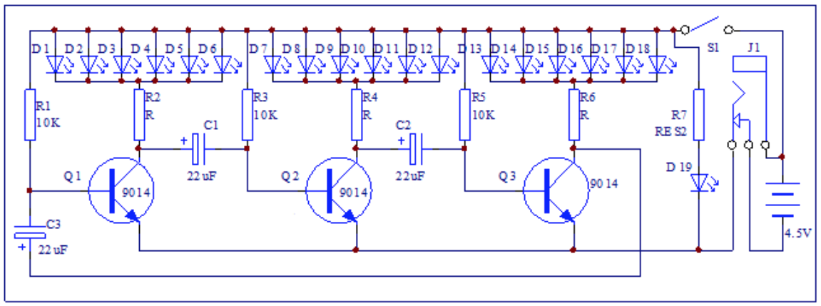
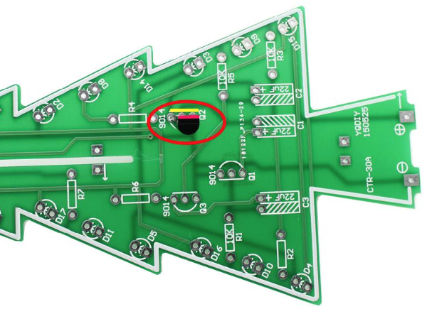
Can someone please support me how to find the issue and how to solved and of course explain what was happening? I think it could be a problem with one of the transistors but I still could not figured out how this tree works.
Thankful for all support,
Richard.