This bit done most recently, so I'll document it first.
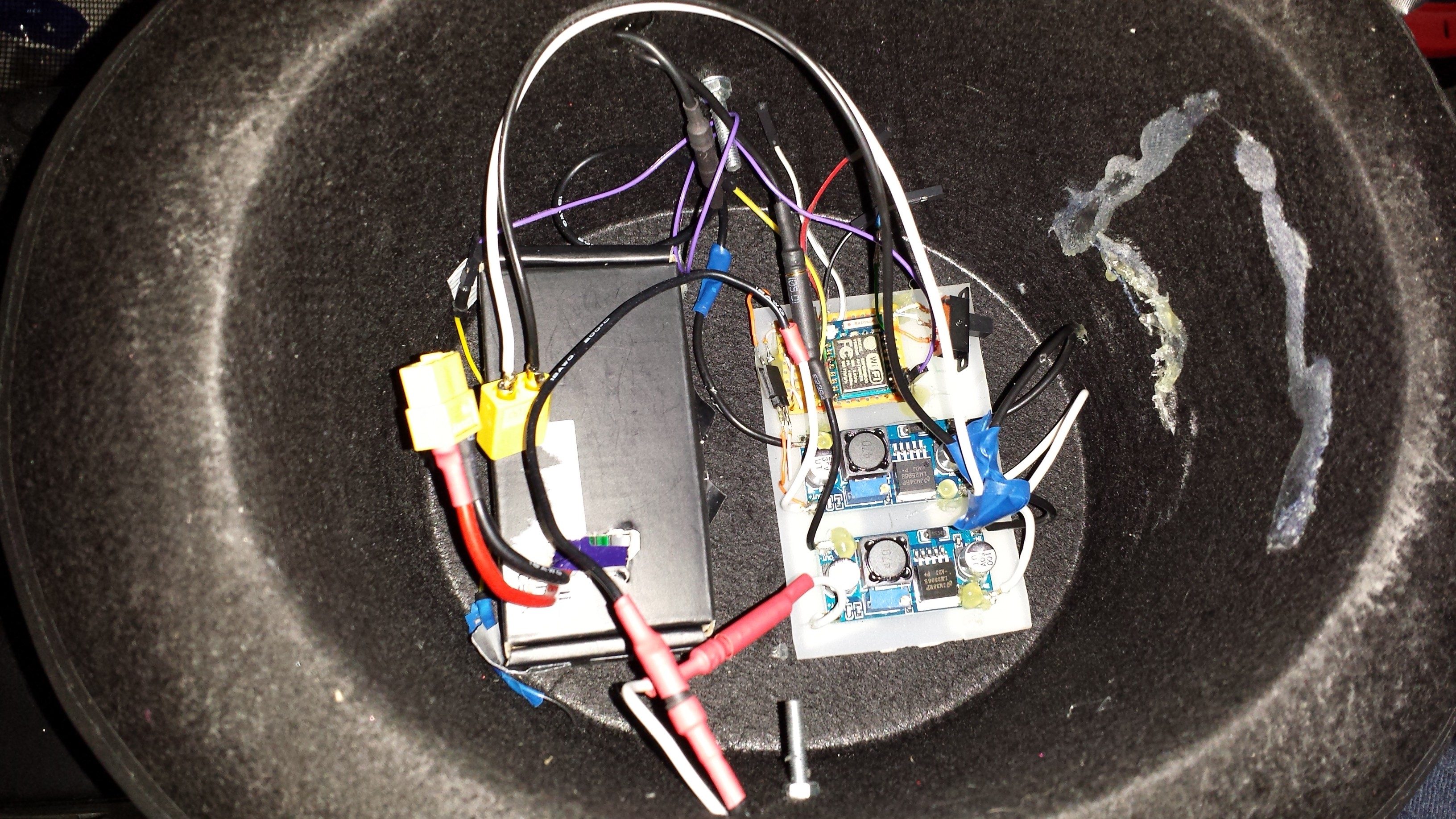
So here is the all-important interior. From this view, the left of the hat is the front.
To point out all the bits and pieces, from left to right -
- The cardboard box the RC battery came in! Strengthened a little with some duct tape, re-openable to replace and recharge the battery, seems to hold it in well. All stuck down with some double sided foam tape.
- A piece of acrylic sheet, stuck down with more double sided foam tape. It is cut down to size to accommodate the DC-DC buck converters, plus a small strip perfboard with which I mounted the 3.3v regulator, ESP8266, a switch for changing between chip program / run modes, and a 3 pin 0.1" header for programming / driving the LEDs. That's the smallest switch I had!
- NOTE - The ESP-07 is of course not 0.1" pin pitched, so I ran copper wires from some stripped CAT5 wires and just connected it all up, getting as close as I can to laying it flat against the perfboard without shorting wires.
- As you can see there's some hot glue residue on the rear wall, this was a failed attempt at mounting the battery on a side wall using some soft material. Turns out it presses against my head when you put it on!
- Wires all over the place, although I do use connectors instead of permanent solder points wherever possible - I've soldered up things and had to dismantle it again when something goes wrong way too many times!
- Various RC motor bullet connectors (heat shrink colour coded for + and -) and an XT-60 battery connector. To dismantle the display from the hat, just unplug all the bullet connectors, disconnect the long thin purple data cable, unscrew the two bolts, push in the sides of the hat, and slide the display forward, being careful not to snag the connectors in the holes.
Why am I using two buck converters? Well because one alone most certainly won't be enough to drive all the LEDs at full brightness, being rated at only 10w each. I power four rows with one, and three rows and the ESP8266 board with the other.
Point of note - I set the buck converters to provide only 4.2volts. Why? Well because the strips are still awesomely bright when fully illuminated at 4.2v, and it allows the 3.3v data signal to work. Ever since I started working with WS2812s over a year ago, I've tried to drive them at 5v with a 3.3v controller (Raspberry Pi's included), many people say it works, or should work, but for me it hasn't worked (reliably) without some kind of voltage boost on the data signal, usually a Logic Level converter. I've also fallen foul of an initial surge, killing the first or second LEDs in the chain as it turns on at 5v (perhaps surging to 7v or 8v). A bad PSU? Probably, but at 4.2v I've never had to worry about it!
The bolts were literally hot glued, head first, onto the left and right inside edges of the 3D printed LED mount pointing inwards, then poked through the aforementioned holes. A washer and nut are done up to ensure a tight fit. I took extra care when poking holes in the hat for these attachment points to make sure I got them in the right place.
There is no connection point on the front of the 3D printed mount, even with the nuts and bolts done up tightly, so it can still rotate up and down a little, kind of like how a helmet visor rotates. This isn't a real problem though as it would only happen when nodding aggressively!
As for the 3D printed mount, this is literally a 3D model curved around the hat brim, with a 'recess' for putting in the LED strips, and they are spaced vertically to allow a nice line-up pattern of LEDs throughout.
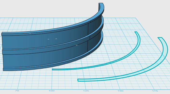
When printing it out, you have to mirror duplicate this shape to go around 180 degrees, then print it out four times. I then simply duct taped the pieces vertically, inside edge only. Because it's 180 degrees round, the duct tape holds the shape solidly.
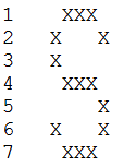
Four prints produce eight rows for the LED strips, but I'm using only 7, so the bottom one is left unoccupied to account for the hat brim, which would otherwise block from view the bottom strip of LEDs. Why 7 rows? Well because it's primarily a text scroller display. 7 rows makes for a nice font allowing for upper and lower case characters (although I've only so far implemented upper case characters), eg -
Each of the LED strips are simply removed from the reel, cut off at 18x LEDs (I originally went with 19x horizontally, but ran into a wiring issue getting them all nicely supported without pulling out the solder joints on the far edges), then the sticky backing is removed and laid onto the mount, ensuring a snug touch with the bottom 'shelf' of each row. A little bit of horizontal nudging helped them all line up.
A pretty unpleasant lengthy soldering process was involved wiring up all the strips, as the small copper pads weren't particularly solder compliant on the top surface, especially seeing as I had to remove some of the weather protective transparent stuff. I ended up soldering up the underside copper contact points instead.
As for the wiring arrangement - I wired up +4.2v to the LEFT side of each strip, and the 0v to the RIGHT side of each strip, all using CAT5 copper. The data connections are arranged left to right, row per row, typewriter style, giving me an easy coding job mapping pixels to X,Y coordinates - pixelnum = (y * 18) + x.
That's about it for the physical build! A lot of overall detail is included here.
Discussions
Become a Hackaday.io Member
Create an account to leave a comment. Already have an account? Log In.