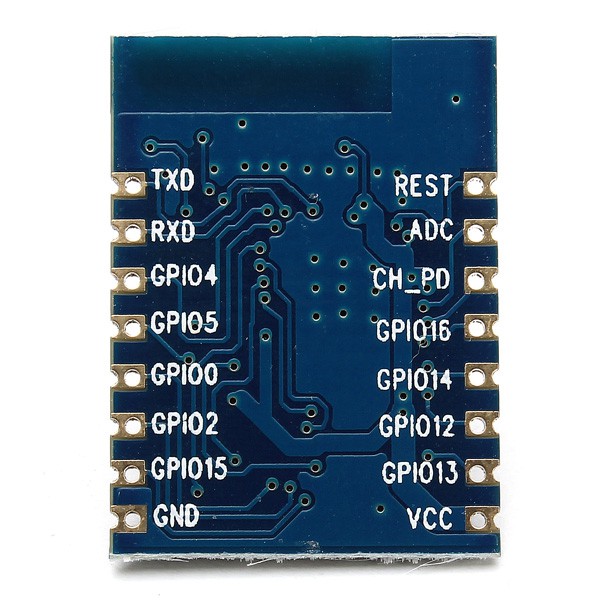
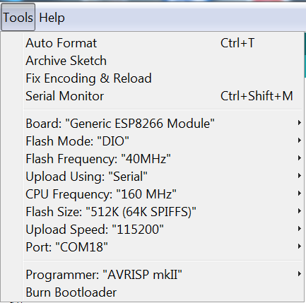
I'm using the Arduino ESP8266 environment, combined with cnlohr's i2s driven LED driver library which was adapted for the Arduino library by 'JoDa'.
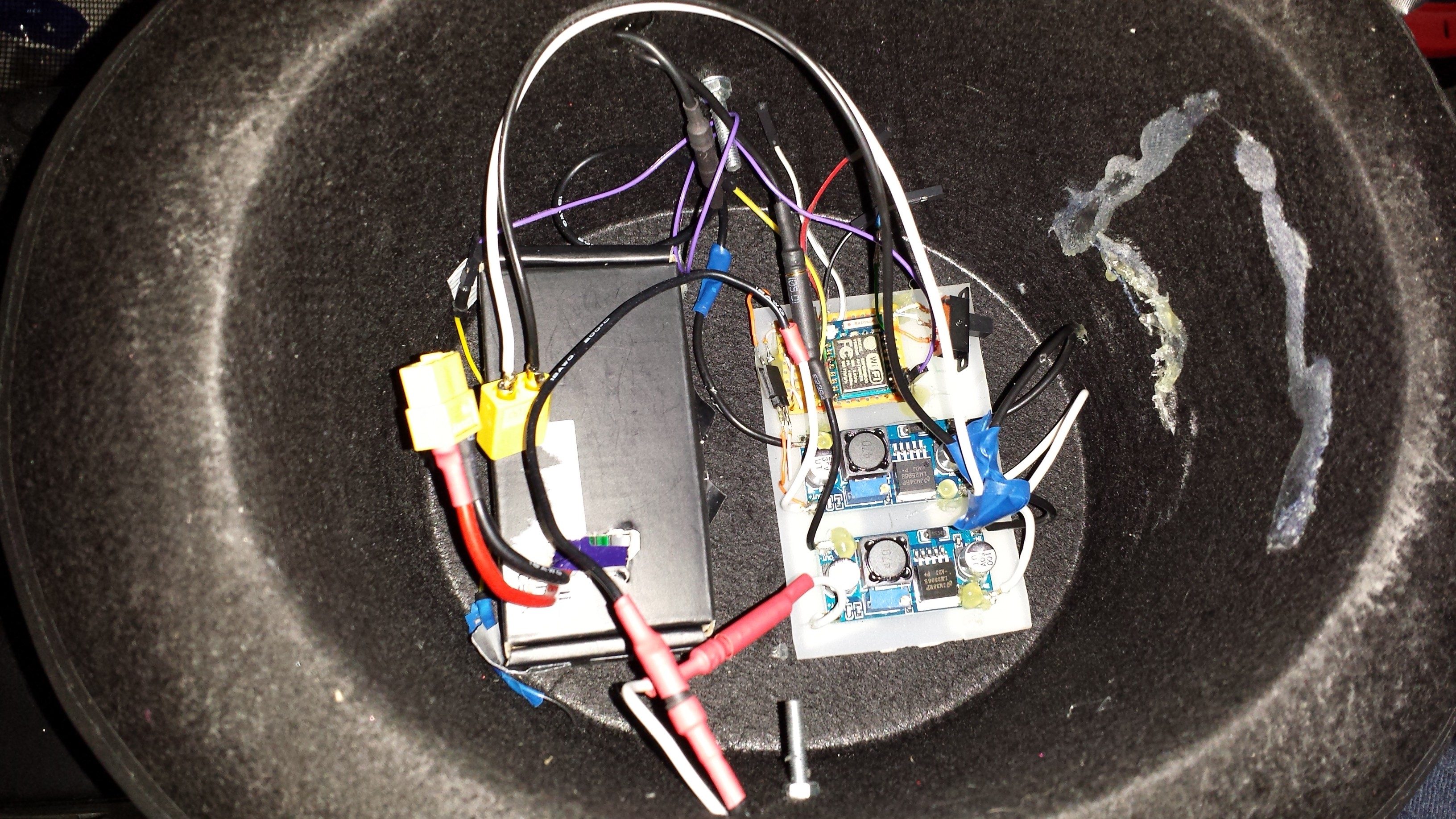
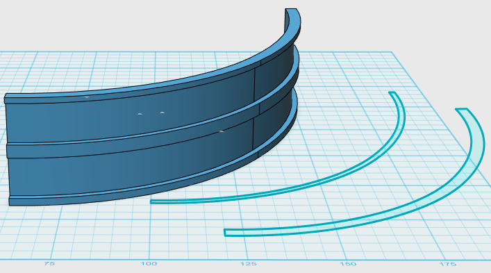
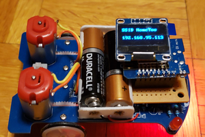
The display is only 18 pixels wide by 7 pixels tall, giving it a modest total of 126 LEDs. This works out okay as too many would be a bit of a power drain - I'm using a three cell LiPo ~1000mAh battery from HobbyKing to provide juice, and because I'm not producing full display brightness (Text scroller for now) it has ran for about two hours straight without running out of battery life - still counting.
I custom wrote a text scroller routine which uses a simple 1 bit / pixel font definition in a simple 2d byte array. The WiFi libraries fully utilised to provide an access point and web page with which you can change the scrolling text, and you can pause the display for a set time with a special character - `.
Here's a very short vid just to get a feel on what it looks like, I'll upload something more substantial soon -
There is also a table of colours you can pick from which changes the text colour in real-time, without needing to restart the text animation. I fully intend to do animatable colours, rainbows, etc, plus basic sprite support, and layered graphics for festive visuals.
This whole development came off the back of a long-term desire I've had to produce LED displays (probably going back 5-10 years!), I have also developed a 16x11 flat WS2812 display driven by a Raspberry Pi, written in pure C, with somebody's DMA based library. Yes it can be done on a RasPi, very reliably, without Linux stomping all over the strict timing requirements of WS2812s.
Future developments -
I have some APA102 LED strips I could change to, although I'm not having any real difficulties driving WS2812's, what with their strict requirements, all thanks to the amazing freely available software libraries.
As mentioned, full layered graphics, sprite support (transparency), possibly even a simple web based gameplay element, where players connect to the ESP8266 and play simple games on the display.
I don't have any real plans for adding audio though.
Apologies for not documenting this during the build, but it was hard work as it is without - I do intend on documenting every part of the process though.
Special thanks go out to CNLOHR and others who toiled over the datasheets to give us really easy to use software libraries for driving these LEDs really efficiently, and thanks to the Arduino on ESP8266 community too.
 jed
jed
 charliex
 David Boucher
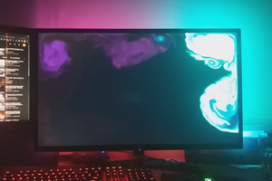
 Kristiāns