-
The Robot
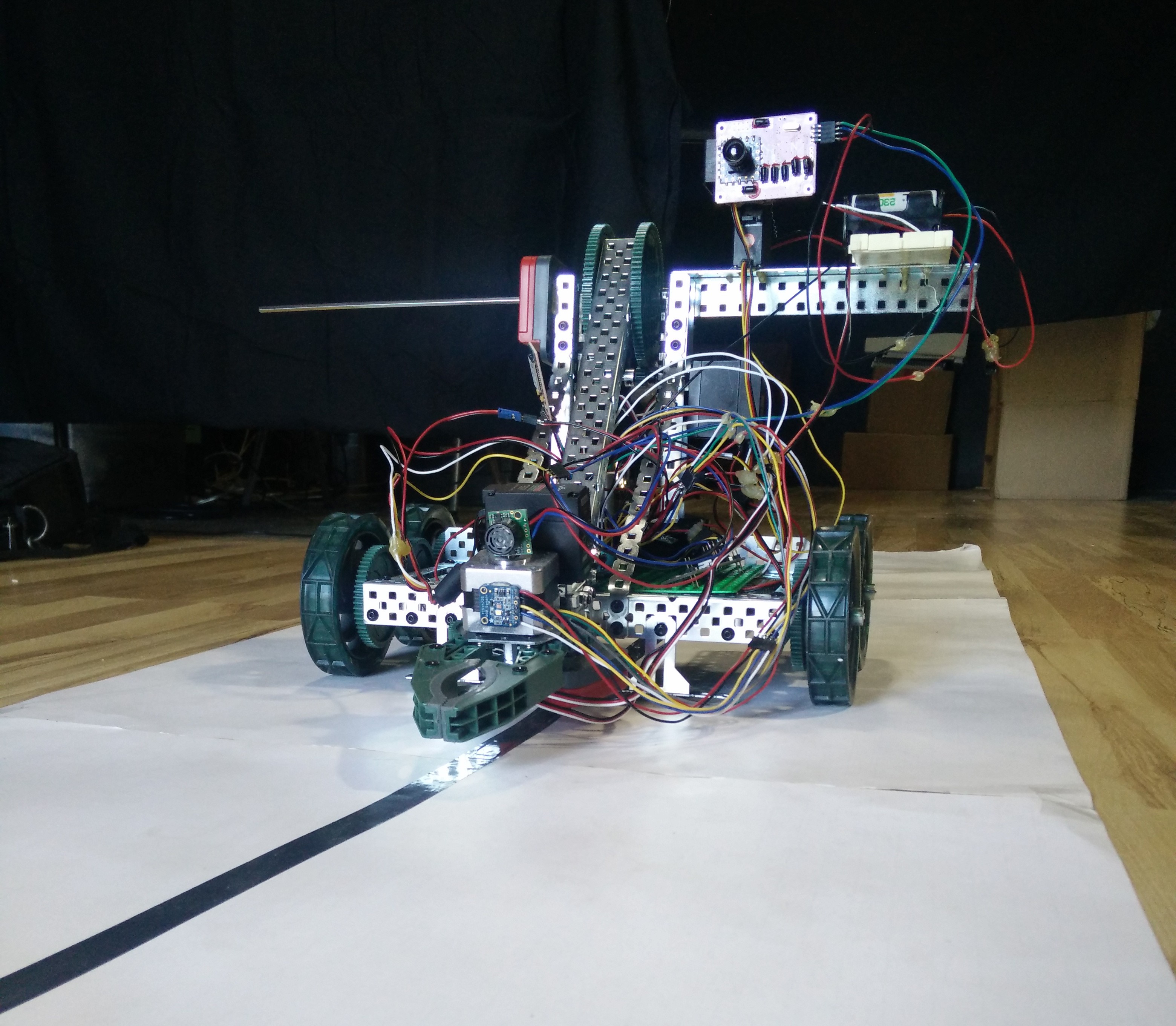
06/03/2018 at 04:32 • 0 commentsSo in order to test everything out, I wanted to create a fully functioning robot that showcases all the functionality of the system. So I ordered a simple Vex EDR clawbot robot with DC motors as the base. This robot has two dc motors for the wheels, plus a DC motor attached to an arm and a DC motor for a claw. I attached 5 line following sensors attached to analog inputs, a stepper motor hooked up to one channel of the motor controller, I put a distance sensor on the stepper motor so that the robot can 'look' different directions, and hooked up the distance sensor to one of the analog inputs. I put a color sensor on the claw, so the claw can tell what color of balls it has. I put rotary encoders on the shafts of the claw and the arm, so that I could do PID control of the arm and the claw. I also connected two servos to a camera, so that the robot can 'look' in different directions with the camera and send pictures back to the control software.
I then wrote a program in the graphical programming software that utilizes every aspect of the hardware. You can click a button and start the line-following. The robot follows the line quickly, all the while updating the dials with current information about the distance to an object from the distance sensor, and the color of any object by the color sensor, the position of the claws, and the light output from the line sensors. Here is the robot:
![]()
-
Control Software
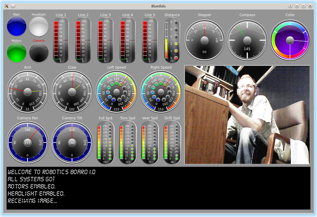
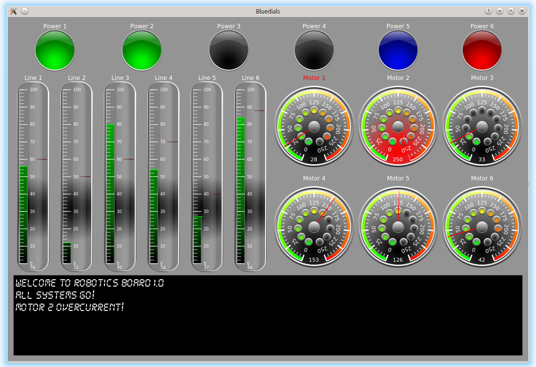
06/03/2018 at 04:15 • 0 commentsAnother aspect of the robotics system that I wanted to add was a way to control the robotics board over bluetooth. Sending commands over bluetooth is easy. But I wanted something that was visually stunning, so that students would get excited about the possibility of controls. Who doesn't love fancy remote controls. So I started looking into how hard it would be to create dials in Qt. I've done quite a bit of widget Qt programming in the past, so it wasn't too hard to throw together some code that was drawing good looking dials. As I went along I kept adding features and making everything configurable, so that an end user could create any kind of control panel they could imagine. This is what I came up with after much fiddling. These are just two examples of what the control panel could look like. Really, all you need to do is configure the text file:
![]()
![]()
I'm really happy with how it came out. All the dials are completely customizable, all the colors, size and position of the numbers, ticks, needles, etc.
-
Board revisions
06/03/2018 at 03:21 • 0 commentsSo now that I had a working board, I had to program it and see how everything worked. I started to find some minor errors with my board right away. Besides the fact that I didn't have the correct serial port brought out to my serial header, there were other minor issues. The boot0 and reset labels were swapped. Also, The DRV8833 has a center pad for heat dissipation, but the center pad didn't have the solder mask set correctly, so I couldn't solder the center pad. It worked, but wouldn't dissipate heat as well as it should. I also wanted to bring out swclk / swdio for easier access in case I needed to program the chip using a standard programmer and not using the serial port method.
So I started making a revision of my board right away. I also started trying to figure out how to program the chip over bluetooth. This ended up being really difficult! As I mentioned earlier, I found a linux program called stm32flash and eventually was able to get it to detect the board using a USB-serial cable. The difficulty here was that the STM32F4 doesn't use 8N1. It actually uses ODD parity! It took me forever to figure that out. So I had to figure out how to set the HC05 serial bluetooth module to ODD parity. Once I did this I was able to program the board over bluetooth!!!
So I sent out to the board house for a another board revision.
But I still was switching the boot0 pin manually. I hadn't realized that when I put the attiny45 footprint on my board, I had assumed that all TSSOP-8 chips had the same width. But apparently, they don't! So I tried to bend the pins on my attiny45 underneath it to solder it onto the pads which were too narrow for it. After trying on multiple boards, I was able to get one of them soldered! After a lot of playing with my arduino code, and working on writing serial code on linux to send out my special command "writeSTM32" which the attiny was looking for to toggle boot0 and reset the STM32 chip. Eventually I got it to work!
So now I was able to wirelessly program and reset my board over bluetooth! What a big moment this was.
So I quickly revised another board revision where I fixed the footprint for the attiny chip so I could have a fully working board with wireless programming! Here is that board:
![]()
Next over the coarse of testing out the board I found a bunch of idiosyncracies with the STM32 board. For example, you can't use InterruptIn pins with same pin number (no PA_12 and PB_12) at the same time. So I wanted the Digital In pins to have different pin numbers for as many of them as possible up front. Also, I found lots of limitations for PWM pins. There are tons of PWM pins, but sometimes a pin is labeled as a PWM pin and another is labeled as a PWM pin, but really, there are relying on the same underlying counter and so can't be used at the same time. ST has configuration software that was helpful to try to look at all the PWM configurations. I also of course still wanted to use an i2c port, two serial ports, and I decided I wanted to bring out an SPI port. I also decided I wanted access to 5v power since some sensors require it, even though their digital inputs and outputs are 3.3 volt compatible. So to be able to use as many sensors as possible, I decided to put a 5v regulator on the board as well.
I also decided I wanted to put a jumper between the STM32 chip and the DRV8833 motor controller. That way if someone didn't want to use all the motor pins, but wanted PWM pins for something, they could be used. Normally they can just be jumpered, but the jumper can be removed and then the board can have 16 different PWM outputs if needed.
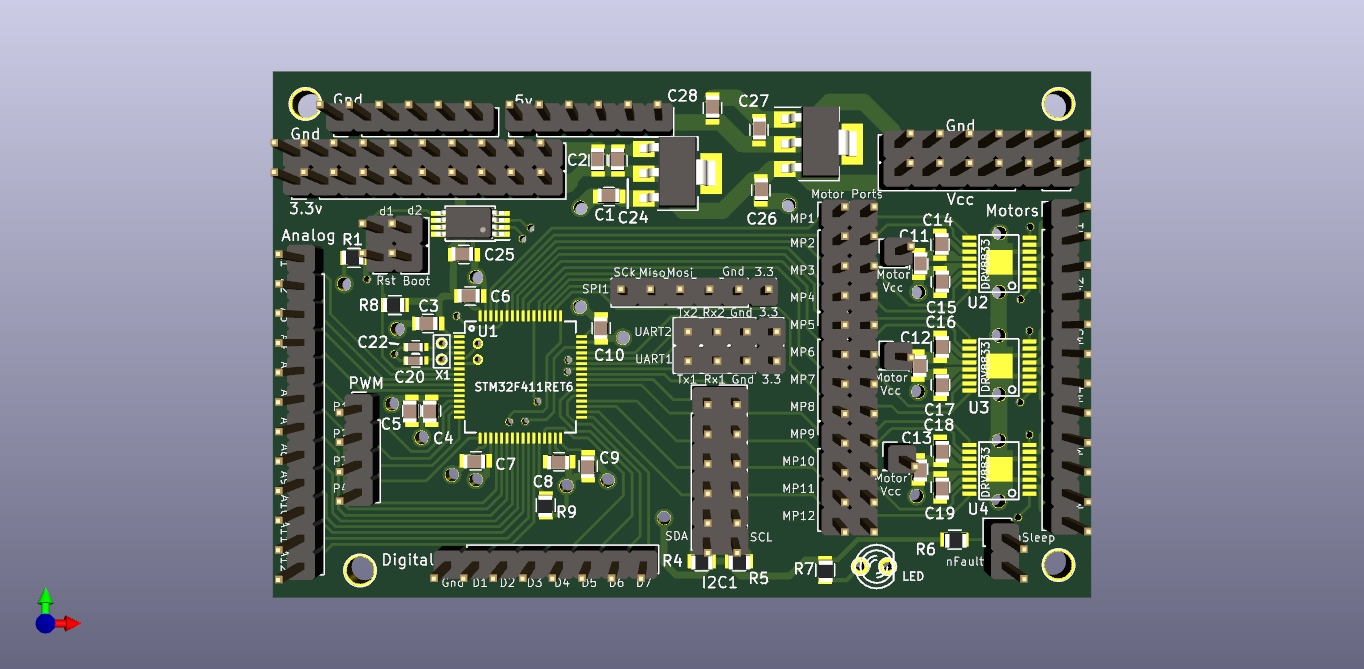
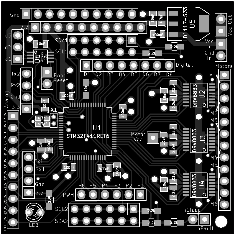
I also wanted to make the board bigger. I found that putting all those jumper wires in the .1" pin headers got a little crazy when I had a complete robot. So I made another revision of the board. Here it is:
![]()
-
My own STM32 board!
06/03/2018 at 02:39 • 0 commentsSo after I made the daughter board for the STM32F411 Nucleo, I started thinking, I wonder how hard it would be to create my own minimal STM32F411 board? So I started looking at minimal circuits online and at ST's documentation. From what I saw, it wasn't too bad! Mostly a bunch of decoupling caps, as well as a voltage regulator with caps, and crystals with caps!
But one of the aspects of the chip though is how to program it? So reading about STM32F4 chips I found that they come with a hardware bootloader that allows programming over the serial port! But in order to program the STM32 this way, there is one pin (boot0), that you need to toggle when powering on the chip in order to boot the chip into programming mode. I wanted to be able to program the chip wirelessly with the cheap and widely available HC05 module. But what a waste it would be if I could program the board remotely, but had to walk over to my robot and toggle it into programming mode and back again. How could I toggle that pin remotely?
After researching and trying to find a bluetooth module that could do this, I found Adafruit's bluetooth module that claims it can toggle an output pin in addition to the serial pins. But Adafruit's module is much more costly than the inexpensive HC05 boards. So I tried thinking about another solution. What if I threw a cheap 8 pin avr onto my board to monitor the serial port and toggle boot0 when it saw a certain serial command over the
line. So I threw a attiny13 onto my schematic and hooked it up to monitor the serial port and toggle boot0. Wanting to keep the board cheap, I picked the cheapest attiny I could. So it didn't have hardware serial support. I also didn't want to have to put a crystal on the board to minimize the part count and cost, but could I reliably detect a serial command without a crystal? I figured since I didn't need to have a complete serial library, all I needed to do was to monitor the line for a small handful of commands. I realized that if my commands are premade to never have more than two of the same bits in a row, any error due to the clock is minimized! In other words, if your clock has a 15% error, it is really difficult (impossible) to tell 7 zeros in a row from 8 zeros in a row. But if you know that all your signals never have more than three same bits in a row, you can easily tolerate quite a high clock error and still reliably detect messages. So I wrote my own arduino code to look for signals that I came up with that have minimal bit switches (like "resetSTM32" and "writeSTM32"). I wrote a C program to generate the bit-string representations of the codes and hoped it would work! In other words, the arduino program does look for "resetSTM32", but rather for {0x12, 0x32, 0xF2, 0x11, 0x11, 0x22, 0xF2, 0x21, 0x32, 0xF1, 0x11, 0x11, 0x22, 0xF2, 0x13, 0x31, 0xF2, 0x21, 0x12, 0x11, 0xF2, 0x13, 0x11, 0x11, 0xF1, 0x11, 0x21, 0x12, 0xF2, 0x21, 0x22, 0xF3} where every four bits represents how many bits in a row stay the same (including the start bit) and an 'F' is a special code that means to ignore the number of stop bits!Next I arranged all the pins to be easily accessible, put the DRV8833 motor driver chips onto my board, the voltage regulator, all the caps, and this was the result:
![]()
Off to the board house. When the boards came back it was time to try to solder the LQFP64! So I went to youtube to try to figure out how to solder surface mount chips. I have done lots of through-hold soldering over the years, but this was my very first attempt at SMT soldering.
So I got a recommended tip and tried the drag soldering technique. I tried and tried and tried and never got good results. Solder bridges everywhere. I'm sure I eventually could have figured out how to do it, other people apparently have perfected the technique. But I decided to try something else. So I ordered a $20 skillet, solder paste, syringes, syringe tips, isopropol alcohol, and decided to try to reflow my board.
After spending time experimenting with tips, I found a tip size that seemed to give a good sized bead of solder across the pins of the LQFP64. I threw it on the skillet to see how it would come out. Not bad! I kept experimenting until I got the hang of how much solder to lay across the pads. Then a little work with a solder wick and it looked like all the pins on the LQFP64 were soldered! Next I put solder on the rest of the SMT pads
and put the board back on the skillet and reflowed it again. It looked like everything was good! Next I did all the through-hole part with my iron and tried to see if I could get the board to boot up!My goal was to be able to program the board over the serial port. But after much trying, I couldn't get stm32flash to detect the chip. I was able to use the STM32F11 Nucleo board as a programmer though. This is a very useful aspect of this board. It has a board perforation that separates the programmer from the simple STM32F4 circuit. So I could break the perforation and use part of it as a programmer. I was able to program my board! So my circuit worked! This was a huge moment for me :)
But why wouldn't programming over the serial port work. I finally realized that not every serial port on STM32 can be used with the built-in bootloader firmware! Deep in the ST docs you can see which specific serial port pins can work with the bootloader. In fact, on my chip, there are only two specific pins that can be used for the serial bootloader, and I hadn't brought them out to the serial port! I was able to hook them up anyway and finally get stm32flash to find my board using a USB to serial cable!
Success!!!
-
Custom Board
06/03/2018 at 00:54 • 0 commentsNow that I had some great visual programming software, I wanted to work on the hardware. I wanted a system that even elementary school children could use. The STM32F411 Nucleo board was great, but not exactly designed for children. So I thought of designing a simple extension board for the Nucleo board that moved all the pins around to allow the students to have all the digital i/o, analog inputs, PWMs, and even motor ports easily coded and accessible. Then all of these pins can be specified in the software so that students can find the pins they are looking for easily (they are color coded)!
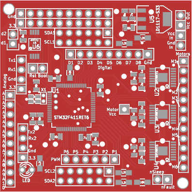
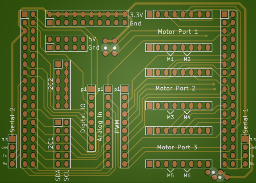
So I pulled out KiCad (I wanted it to be open source!), and starting on a board. This is what I came up with:
![]()
I ordered the boards from DirtyPCBs, and everything worked! It really was just a simple pin mapping board, what could have gone wrong!? The three motor ports were designed to plug in DRV8833 Dual Motor driver boards from Pololu and to plug in a HC05 Bluetooth serial module into one of the serial ports. But the ease and price of creating a board (it had been some years since I created a board, back when it used to be more expensive!), made me start thinking...
-
Time for software
06/03/2018 at 00:27 • 0 commentsHaving fun with the STM32F411 Nucleo board was great. It got me excited to build robots based off of it. But what I really wanted was a learning platform. I had no idea if I could find good software to program the board. So I looked. And looked and looked. But none of the visual programming software that I could find did what I wanted it to. Notably, I couldn't find any software that showed a correspondence between visual blocks and code produced.
So I thought, I wonder how hard it would be to create visual programming software? So I jumped into my favorite programming environment (Qt). I really like that Qt is built off of C++ so it is fast. I also like that it is cross platform. I can write code once and port to Linux, Windows, Mac, Android, iOS, and more. I have used Qt extensively in the past and am familiar with most of its library functions, but hadn't used the graphics class that I suspected could be very useful to making a graphical code editor before: QGraphicsScene. It handles drawing, moving, and all the basic functions of handling tons of graphics objects. So I dove in and quickly found a helpful example of the class called diagramscene.
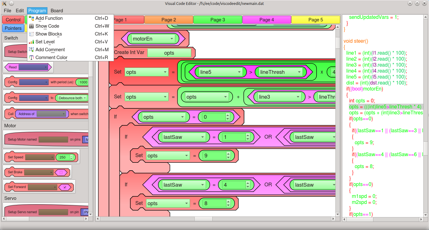
After only about 6 hours of playing with diagramscene I had a quick a dirty prototype! I was amazed. I had code that drew various types of blocks that were expanded to fit other blocks in them based on what type they were. At that point I knew that I could create an entire visual code editor. And so over the following months that is what I did in my spare time. I worked on the software on and off throughout 2015. I kept working on the software and improving it, adding functionality, until I had a fully functioning visual code editor!
One of the main goals for the software was to make it extensible. I wanted every aspect of the visual editor to be extensible and configurable. So I made it so every block in the program comes from a configurable text file. The code that the block generates, its look, color, type, and even level, is all set in the text file. Being that the software is designed to be geared around teaching, each block is assigned a different "level" so that lessons can be designed to progressively introduce new features and concepts without overwhelming beginning students.
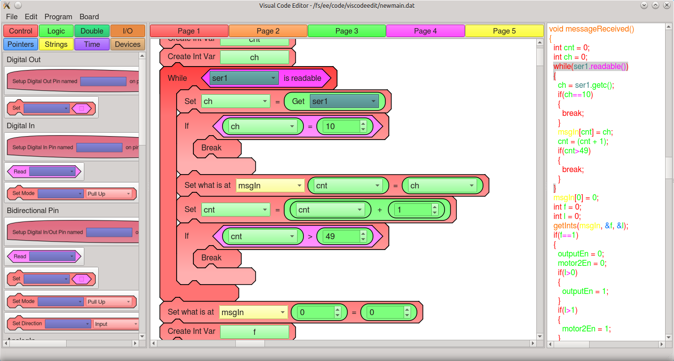
One of the key features is to show students how the visual blocks correspond to code. So each block is color coded and the software automatically generates code that matches the color of the blocks. Furthermore, students can select one or multiple blocks in the visual editor, and the code editor will select those same blocks in the code so that students can see what code their visual blocks generate.
I also worked to make it a user friendly application, with common features like save/open, import/export, zoom, copy/paste, printing, comments, functions, as well as programming, pausing, reseting, and controlling the board. But more on the control software later.
Lastly, I also wanted to software to run on low cost hardware so that expensive computers wouldn't be needed to setup an entire lab. Given the fact that the software is written in native C++, this was achieved. In fact, the software runs great on a Raspberry Pi, perfect for setting up an entire low cost lab! I also didn't want the software to be dependent on the cloud, thus needing an (possibly flaky) internet connection. So all of the software run locally, enabling it to be a very responsive native app. Plus, the entire environment can be setup once, and a Raspberry Pi SD disk image can be cloned so that an entire lab can easily be setup very quickly, without having to install and maintain many traditional desktop computers.
Sample Screenshots:
![]()
![]()
A full sample program:
![]()
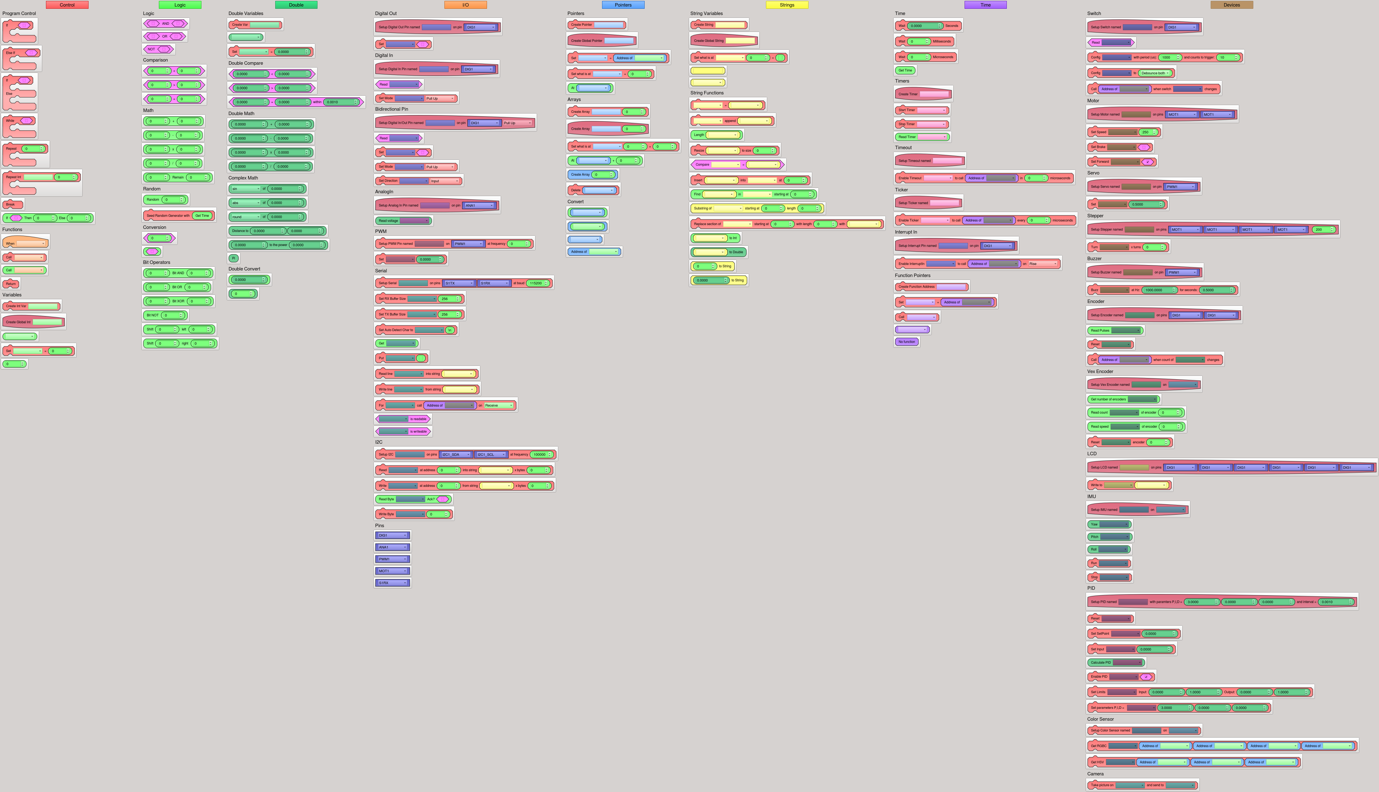
All the blocks currently in the system:
![]()
Sample blocks in the text configuration file:
IfElse/shapeID=DualCondition IfElse/blockType=Statement IfElse/inputs="TopOfIf|MidOfIf" IfElse/menu=1 IfElse/level=3 IfElse/code="if(|in1)|n{|n|I|block1}|i|nelse|n{|n|I|block2}|i|n" IfElse/comment=If/Else statement DigitalOutWrite/shapeID=Statement DigitalOutWrite/blockType=Statement DigitalOutWrite/menu=4 DigitalOutWrite/level=1 DigitalOutWrite/inputs="Text|UseDigitalOutVar|Bool" DigitalOutWrite/inputStrings="Set||" DigitalOutWrite/comment="DigitalOut var" DigitalOutWrite/code="|in1.write(|in2);|n" ColorSensorGetHSV/shapeID=Statement ColorSensorGetHSV/blockType=Statement ColorSensorGetHSV/menu=8 ColorSensorGetHSV/level=71 ColorSensorGetHSV/inputs="Text|UseColorSensorVar|AddressOfInt|AddressOfInt|AddressOfInt" ColorSensorGetHSV/inputStrings="Get HSV|||||" ColorSensorGetHSV/comment="Get HSV data" ColorSensorGetHSV/code="|in1.getHsv(|in2, |in3, |in4);|n" -
First Steps
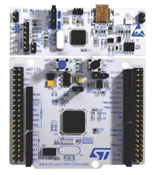
06/02/2018 at 23:57 • 0 commentsAs I saw the need for an open and extensible robotics system that could address the needs I saw, I began looking for what systems were out there to address the various needs. I knew I would need to start with a solid chip at the heart of the platform, one that had great compiler and tools support and plenty of libraries to make extending the system easy. An obvious candidate could be an AVR chip. With Arduino built on top of it, there are very many libraries and support for various free compilers and build environments. But ideally I wanted something more powerful and extensive, without skyrocketing costs. Starting to look into various embedded ARM chips I came across the mbed platform. After buying a couple of evaluation boards, I came across the STM32 nucleo boards (specifically the STM32F411 Nucleo board). At only around $12 per board, the cost wasn't prohibitive, and the capabilities on the chip allow far more extensibility than any 8-bit AVR's. The board simultaneously allows 7 digital pins (with interrupt capability), 12 analog in pins, 16 PWM pins, 2 serial ports, an I2C port, and an SPI port to be used!
So I bought a STM32F411 Nucleo board and started learning about the mbed environment. I was immediately impressed with how easy it is to use, especially to get started with the online compiler. I also saw that you can download the complete mbed environment and libraries to be used with a free C++ compiler (gcc).
So at that point I felt that this was a good system to build a robotics platform off of. But I still needed to have a way to program it visually...
![]()
-
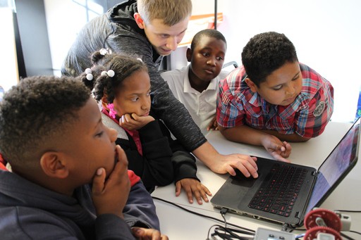
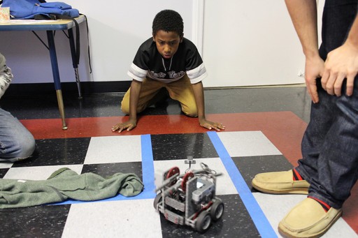
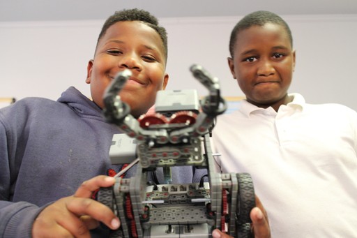
The need
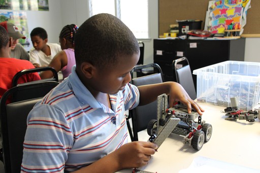
06/02/2018 at 23:29 • 0 commentsThe beginning of my project started back in early 2014 where I started and ran an after school robotics program in South Central Los Angeles. I began looking for different robotics platforms to teach robotics to 4th-6th graders as a way to get them excited about learning STEM. I wanted to run a pilot program with around a dozen kids with hopes to grow the program to address the great need in South Central Los Angeles for STEM education and good after school programs.
I decided to use Vex IQ which had recently came out for my pilot program. While there are many good aspects of Vex IQ, many of the shortfalls of it and of other platforms available became apparent through the pilot program.
First of all is the cost of various platforms. When teaching robotics in low income neighborhoods, it is very important to to keep the cost of the program down to reduce the need for outside support and make the program sustainable.
Secondly is the need for the platform to be open and extensible. While Vex IQ is a nice platform in many ways, I wanted a platform that I could take from the basics of robotics, all the way through advanced topics without switching platforms. Since most of the commercially available systems are closed, there is no ability to add new sensors and interface to other systems.
But that brings me to the biggest issue I had with all available platforms: the programming environment. I wanted a visual way to program robots for beginners, but also a way to see how the visual representation of program flow translated into actual code so that students could seamlessly advance from visual programming to programming in C++ as they advanced. I was unable to find a visual programming environment that showed how each visual block translated into actual code. Along with the fact that most visual environments are proprietary, not extensible by the user, and often costly, made me feel the need for a open system for teaching robotics that could address these and other needs.
Despite the many challenges of working with Vex IQ, the initial pilot program went well and was a big hit with the students. It only made me long for a better system that could better facilitate STEM education for those who need access to it.
![]()
![]()
![]()
![]()
-
Status Update
04/20/2018 at 18:13 • 0 commentsThe current status of the Visual Robotics Platform is that the Visual Programming and Control Software are stable and working well. I have the 4th revision of the board back from the board house, and have the components, but need to solder and then test the boards. I need to do a lot of work in documenting the whole build process, commenting and releasing source code, and cleaning up and releasing schematics. I'm also considering what type of (Open Source) licenses to choose. I also got laser cut acrylic color printed with labels for the pins to make a case for 4th revision of the board.
Also, I've used the board and software to create a fully functioning robot with an arm and claw, with a stepper motor with attached distance sensor, optical sensors for line-following, color sensor, two servos to move a camera, four DC motors for movement and the arm/claw, quadrature encoders for PID control of arm/claw, and bluetooth. All of the sensors and motors can be programmed and controlled via the created visual software.
Visual Robotics Platform
A low-cost STM32 board with motor controllers created along with visual programming and control software for use in education.