0%
0%
 Tobias Rathje
Become a Hackaday.io member
Already have an account? Log in.
Just one more thing
To make the experience fit your profile, pick a username and tell us what interests you.
Pick an awesome username
hackaday.io/
Your profile's URL: hackaday.io/username. Max 25 alphanumeric characters.
Pick a few interests
Projects that share your interests
People that share your interests
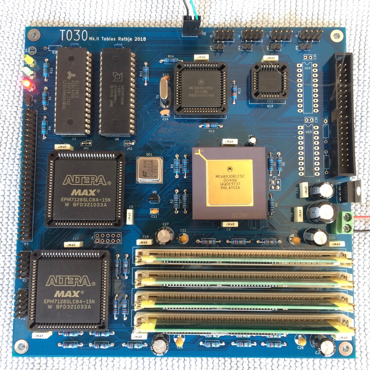


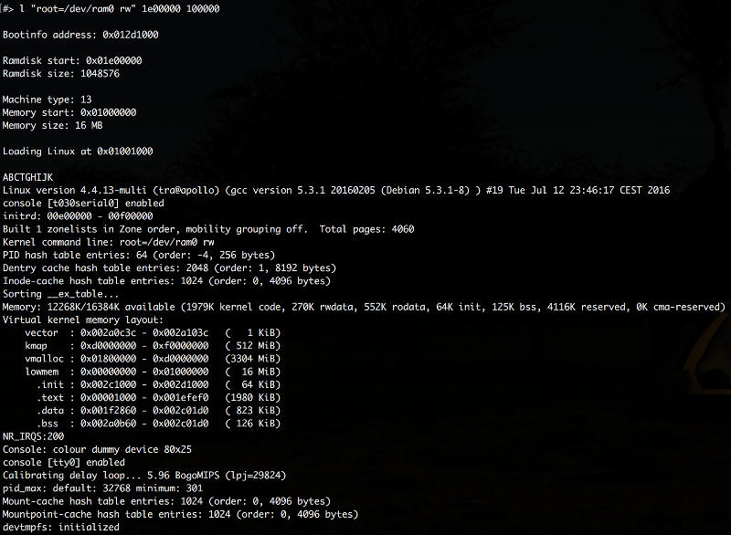
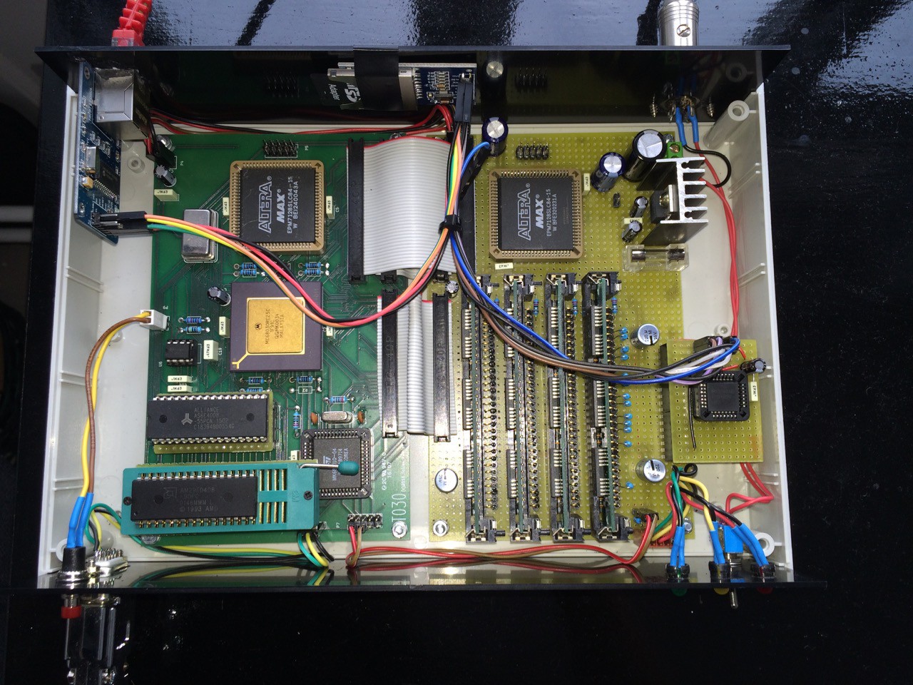
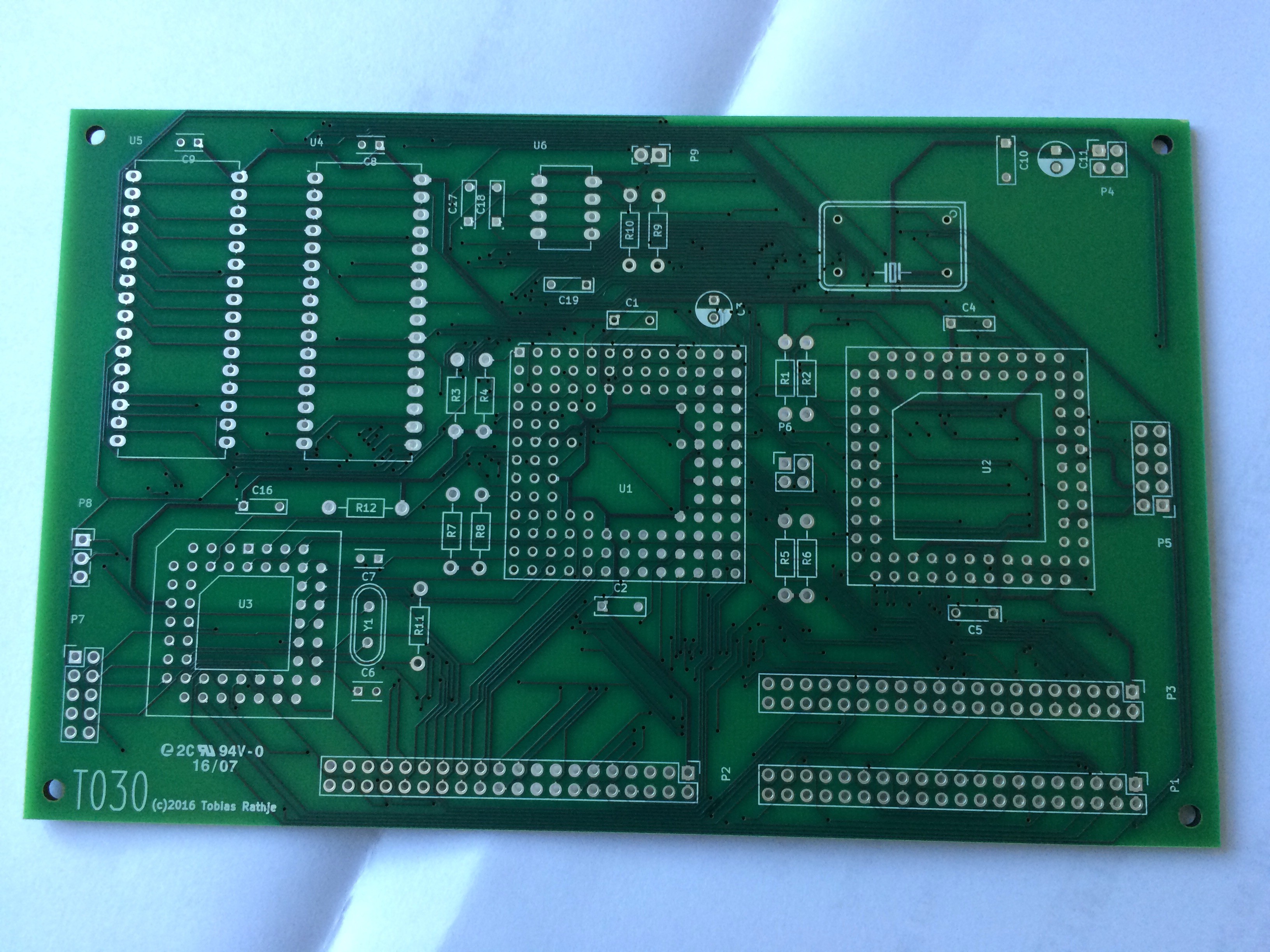
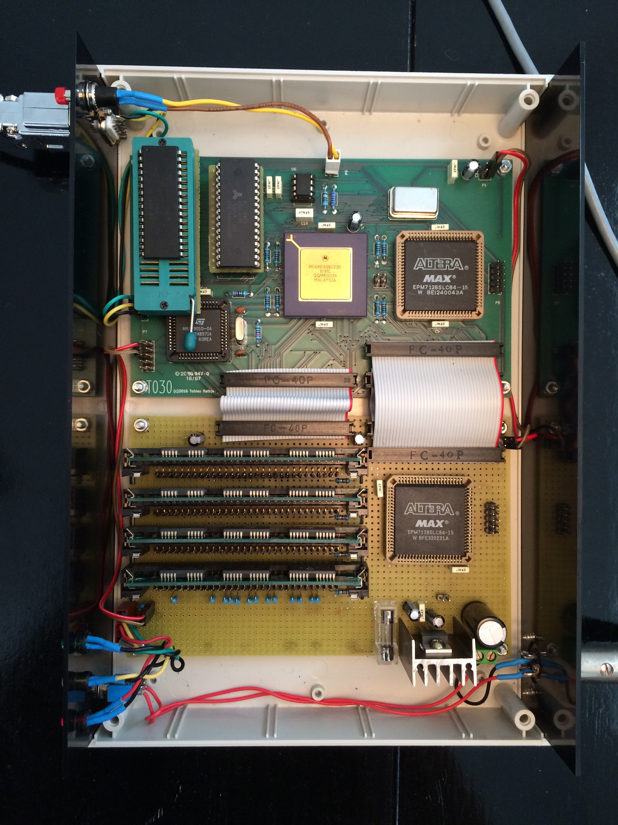 I have implemented a DRAM controller in a second MAX 7128 CPLD. The controller is implemented as a FSM in VHDL and performs CAS before RAS refresh, address mux and data size decoding. I have never used VHDL before but a design example along with some sample code from an RD document from Lattice got me going in the right direction.
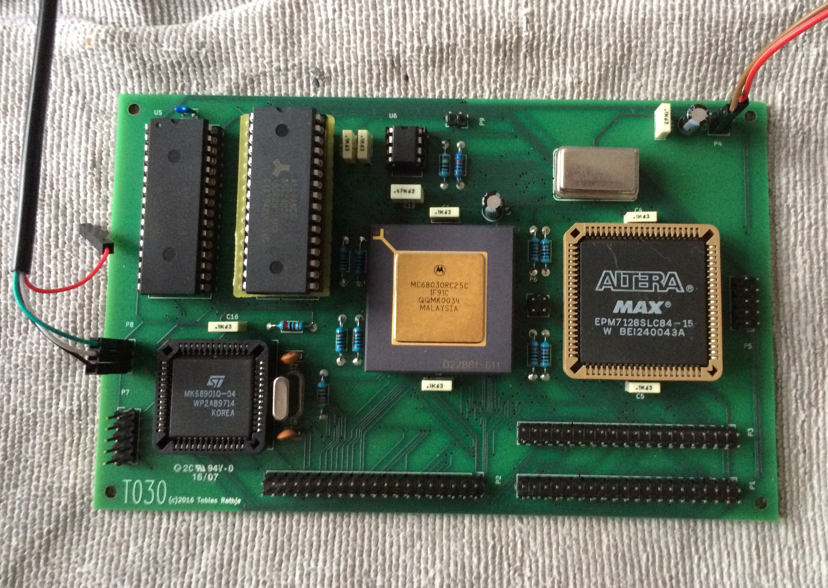


 Colin Maykish
 Keith
Keith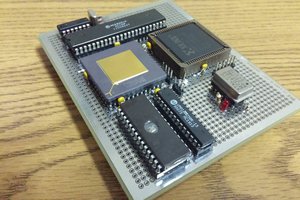
 Jason Westervelt
 Tom
Tom
Hi,
for your next Mark revision please consider Legacy PCI expansion slots and an ATX motherboard form factor. TNX!