SHAOS
SHAOS-
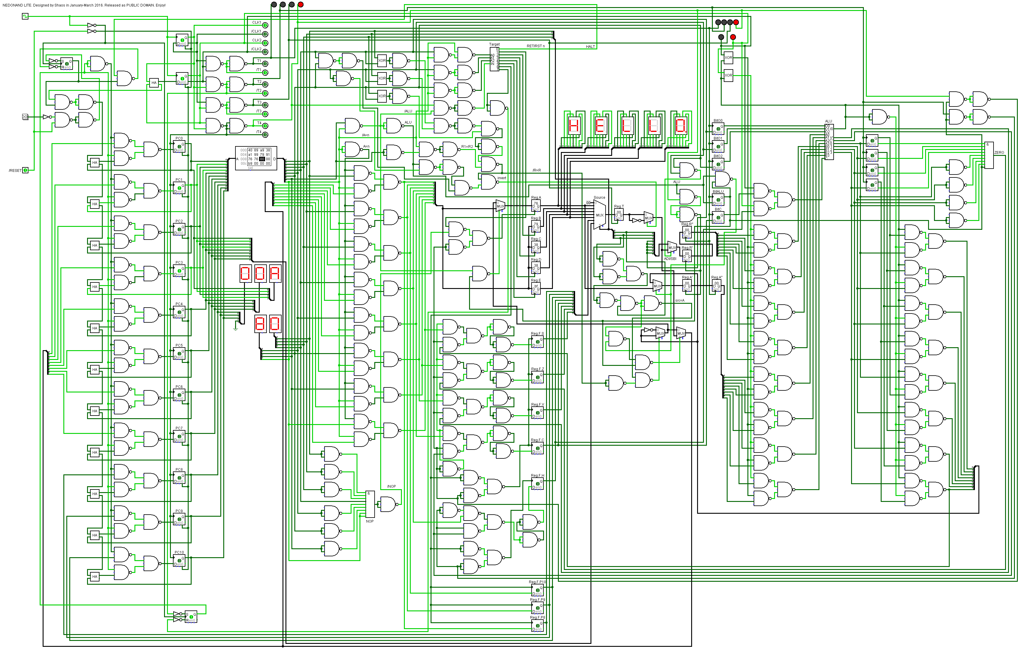
NEDONAND LITE with HALT mode
03/27/2016 at 01:35 • 0 commentsI added HALT mode into simulation - if any instructions from range 0x80...0x87 is executed (these are placeholders for future RET and RST n) then processor is HALT until user pressed GO button (on the left side of simulation):
![]()
It may help to run large test program when result of every sub-test is displayed on 7-segment indicators with following HALT and when user checked the result he/she may press GO button to run to the next sub-test and so on.
Logisim simulation file was updated: nedonand.circ
P.S. This behavior will still be available even in future full-scale NEDONAND when RET instruction is called from the main program (return stack is empty in this case)
-
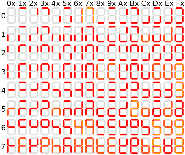
7-segment characters
03/27/2016 at 12:24 • 3 commentsThere is a very useful Wikipedia article about this topic:
https://en.wikipedia.org/wiki/Seven-segment_displayEspecially the table with 128 7-segment "characters" - I put hexadecimal digits around it to make it easier to see what to send to the register to display (and highlighted everything looks like numbers or letters):
![]()
NEDONAND LITE has this table for "characters" with codes from 0x00 to 0x7F - and next 128 characters with codes from 0x80 to 0xFF simply add a dot at the right-bottom corner. Five indicators display content of 5 registers A, B, C, D and E.
-
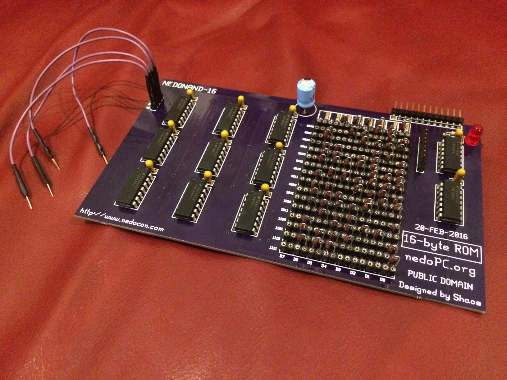
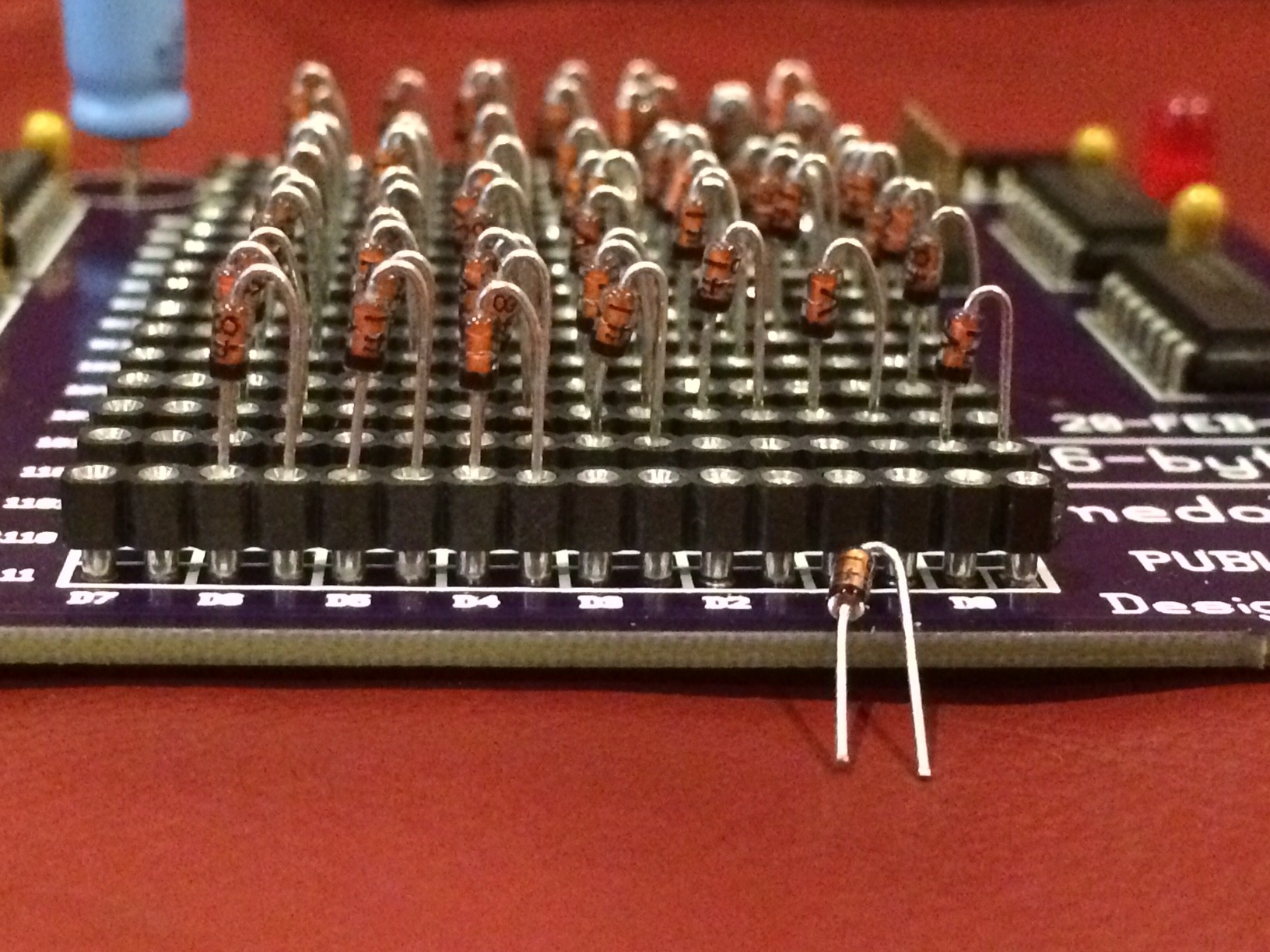
Board NEDONAND-16 tested
04/05/2016 at 04:36 • 2 commentsFinally I completely built and tested NEDONAND-16 board that is MPROM (Manually Programmable Read Only Memory ;)
![]()
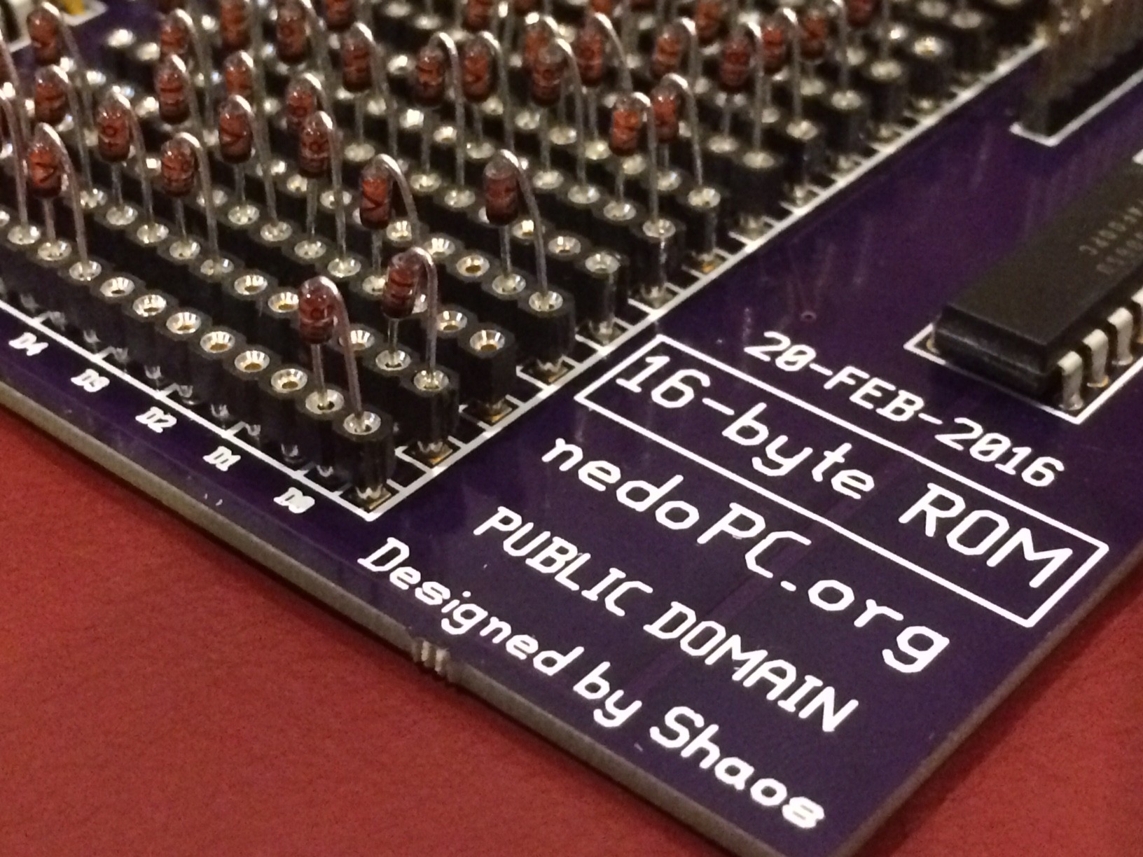
It's programmable by inserting diodes into holes in proper places:
![]()
In order to do that diode's terminals must be specifically formed:
![]()
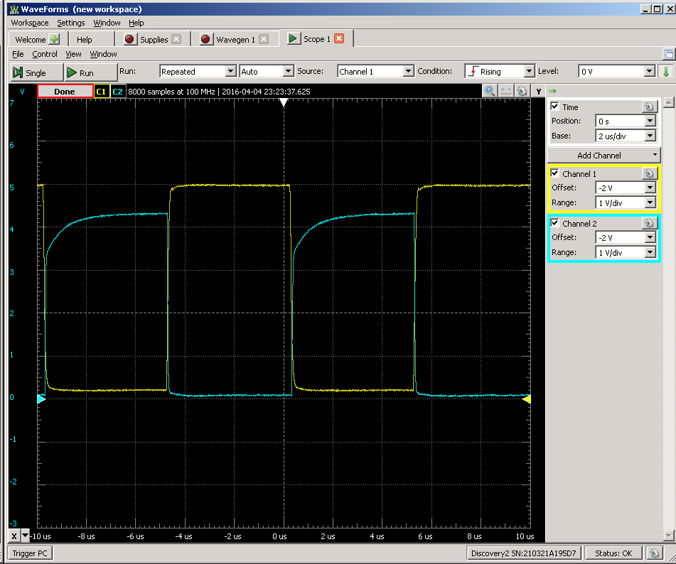
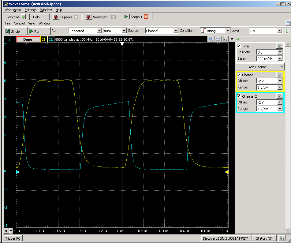
I connected it to my Analog Discovery 2 and tested its limits in terms of frequency:
![]()
So this is 100 kHz:
![]()
And this is 1 MHz - should be good enough for TTL:
![]()
P.S. But I redo this board anyway, because couple wires still may short on some copies of the board...
-
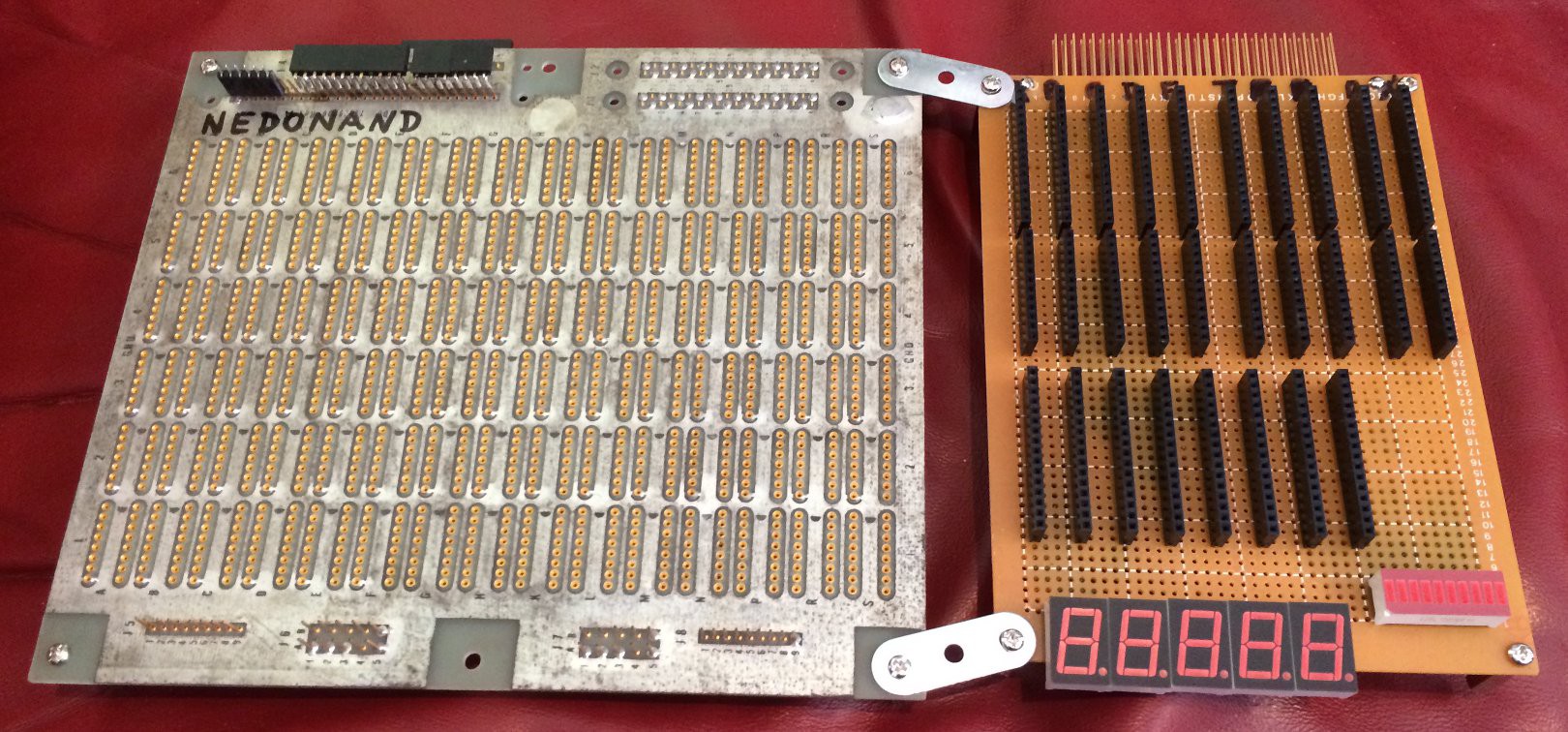
Wirewrapping Motherboard
04/17/2016 at 22:10 • 3 commentsThis is a motherboard to connect all parts of NEDONAND together. I decided to use "wire-wrap" technique, but because female header receptacles are relatively new and not exist in wire-wrapping form (with long terminals with square post) I used "side-kick" soldered board where I collect all header receptacles for NEDONAND boards (probably I will need another one to host everything):
![]()
On the top of a side-kick you can see sockets for registers A,B,C,D,E and T (temporary register) and some other things as multiplexers and demultiplexers. Five 7-segment indicators will show registers contents (directly without decoding) for registers A,B,C,D,E and 10-LED bar graph on the right to show content of register F plus 2 additional signals (as ALU usage flag for example). Golden header on the very top of a side-kick is an interface between wire-wrapped universe and soldered universe to make things easier...
-
NEDONAND won 1st round of the Prize!
05/02/2016 at 17:21 • 3 commentsNEDONAND became a finalist of the 1st round of Hackaday Prize 2016 along with other 19 great projects!
![]()
Thanks to everyone involved :)
http://hackaday.com/2016/05/02/these-20-projects-won-1000-in-the-hackaday-prize/
NEDONAND homebrew computer
NEDONAND is 8-bit homebrew computer entirely built out of many 74F00 chips (2-input NAND gates)