Close
0%
0%

3D printed truck

3D printed running aid

Similar projects worth following
The ultimate running aid was big enough & the 3D printed truck became so big that it was decided to separate the 2.

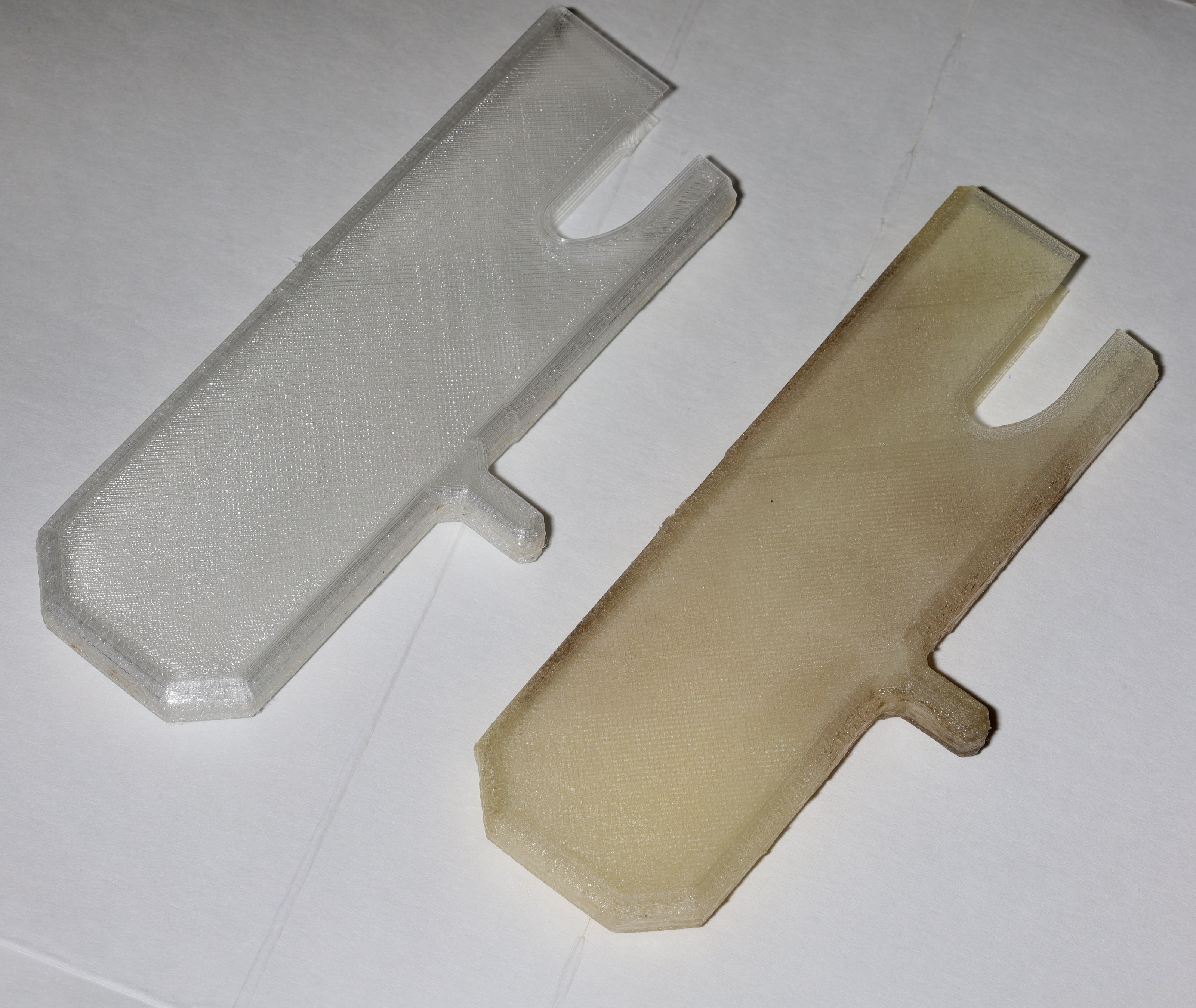
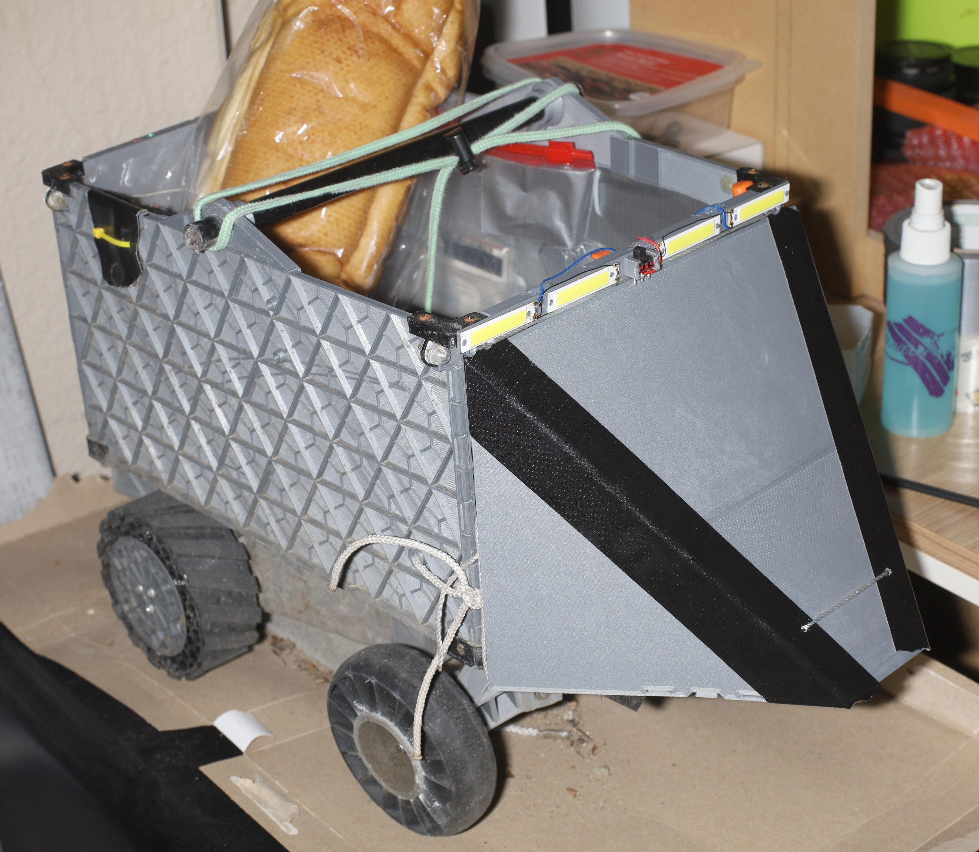
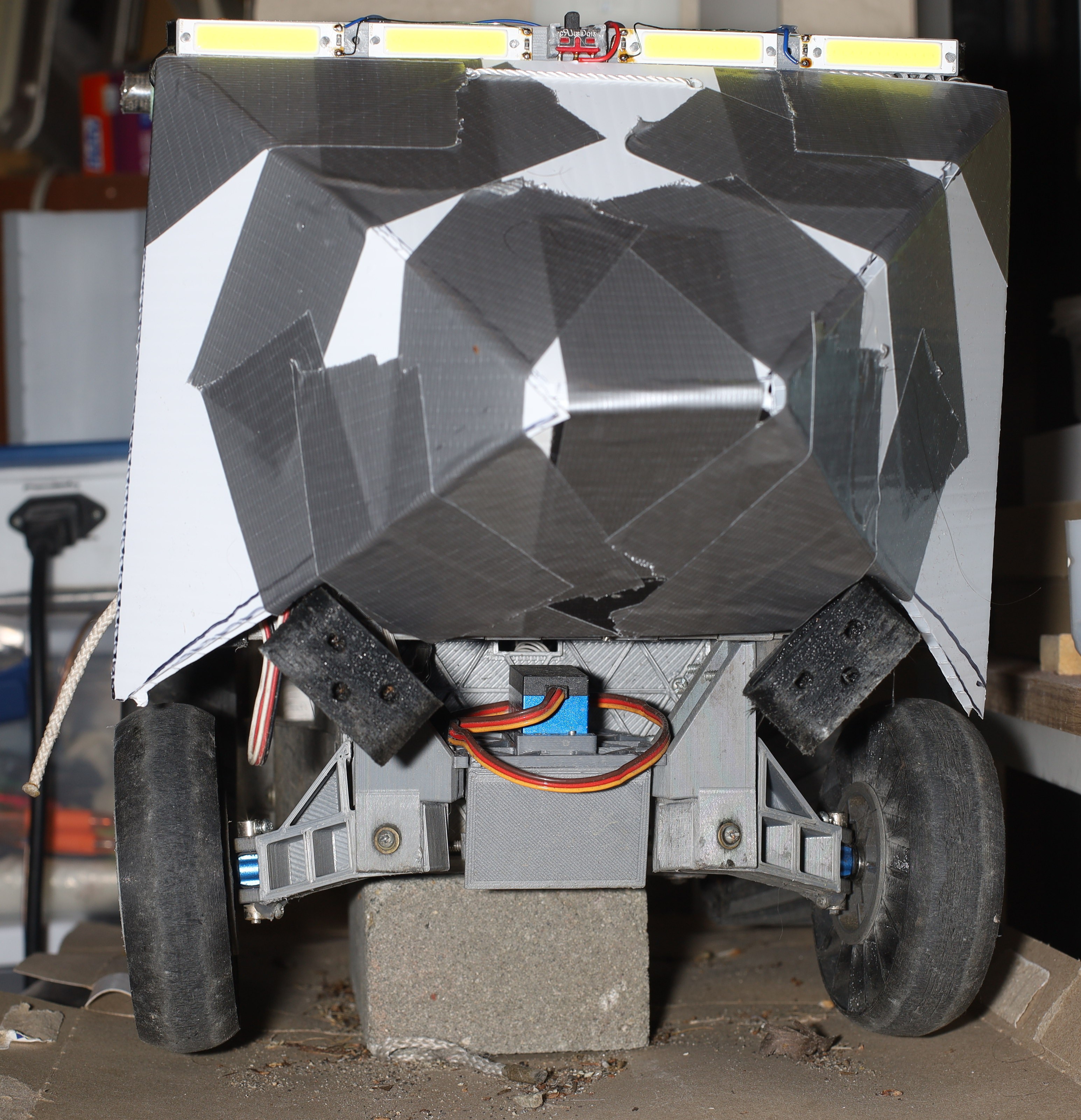
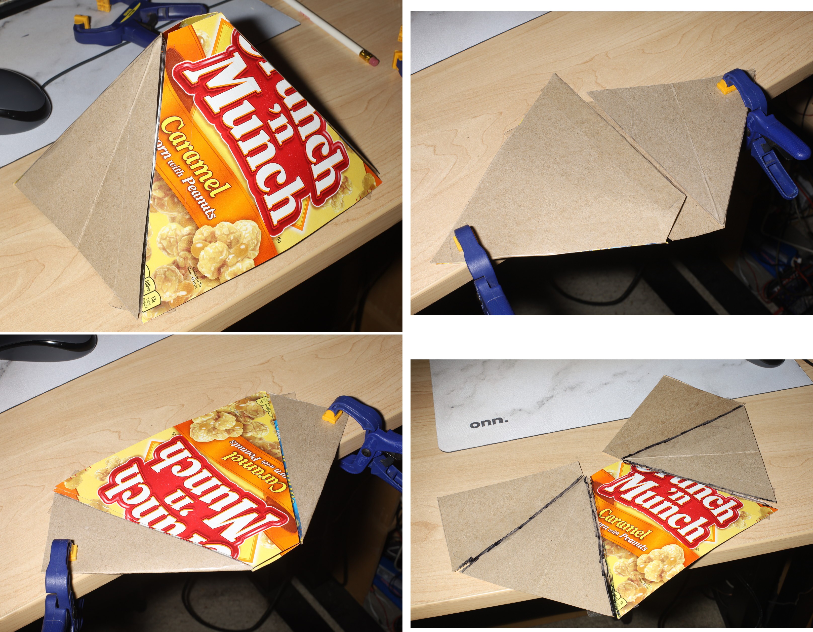
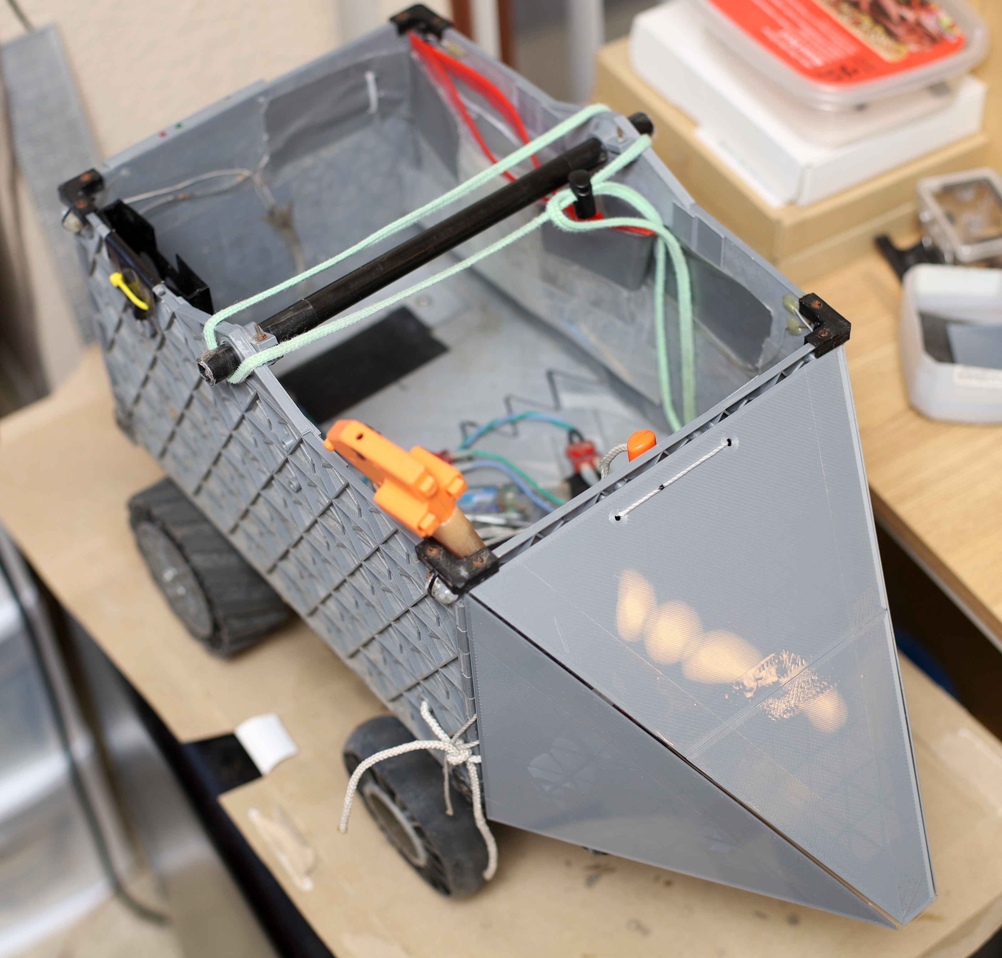
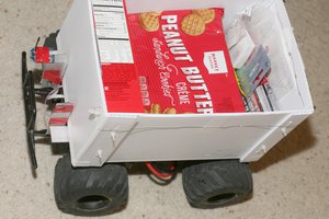
The high cost of good RC truck kits, diminishing need for such kits & the noise of gearboxes made lions look elsewhere for a robot platform.  3D printing a truck from scratch, with only a few metal parts still being off the shelf, was the next step.  The only parts which have to be outsourced are the motors, steering servo, & steering knuckles.  Everything else is 3D printed, made of coroplastic, or home made electronicals.  The size was based on the original Tamiya lunchbox.
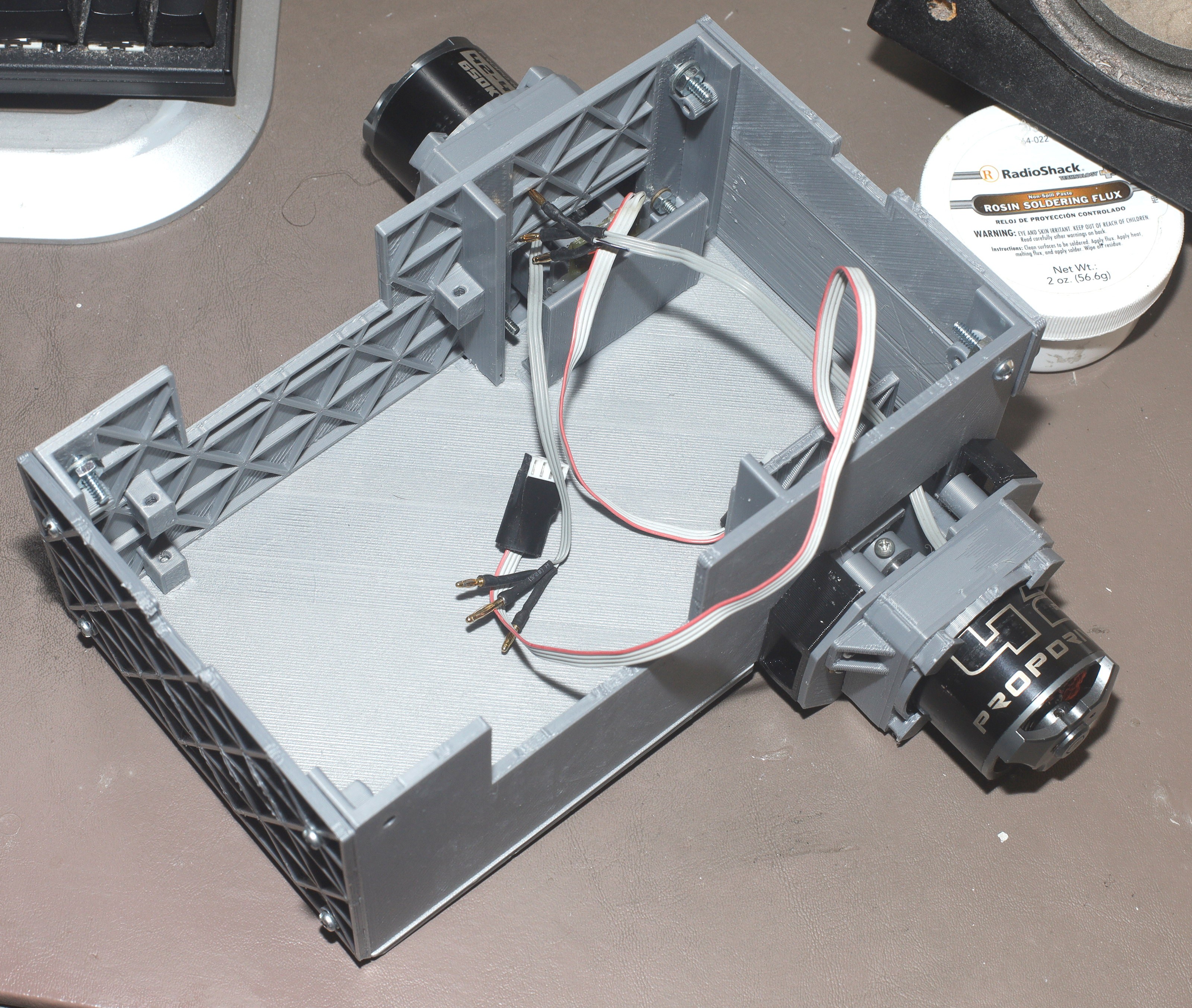
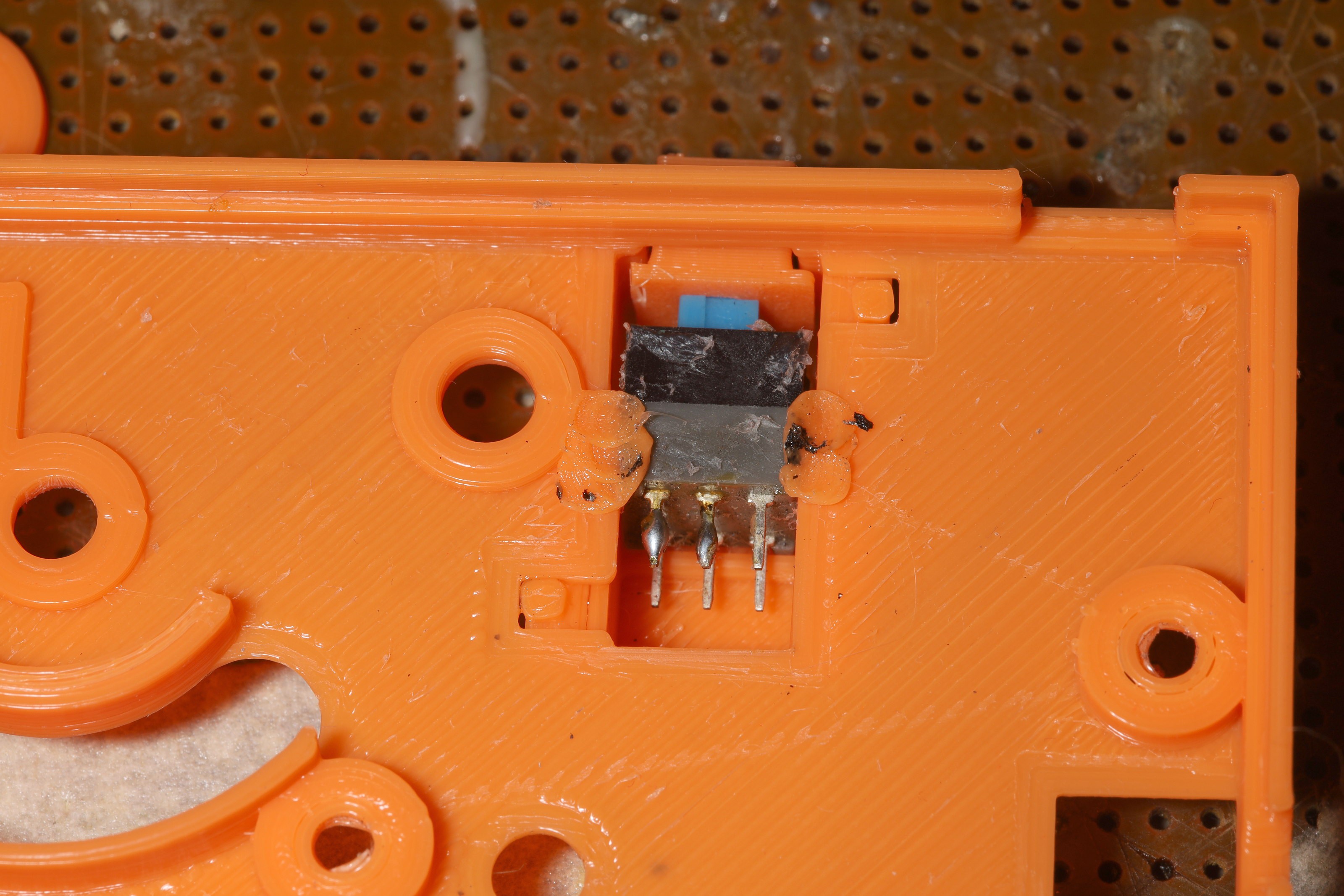
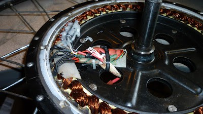
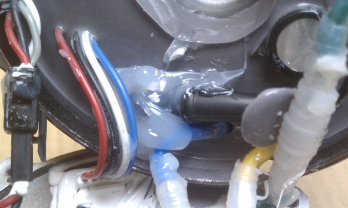
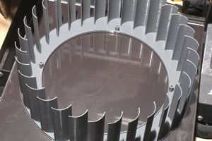
Motors: 

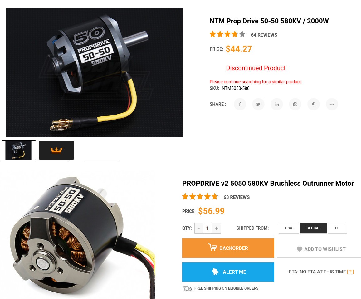
Motor numbers are comprised by their diameter & length, so a 4248 has a 42mm diameter & 48mm length.

The current ship has a Propdrive 4248 of any KV rewound with 20 turns of 26AWG according to the diagram.   It doesn't produce enough torque to go up hills.

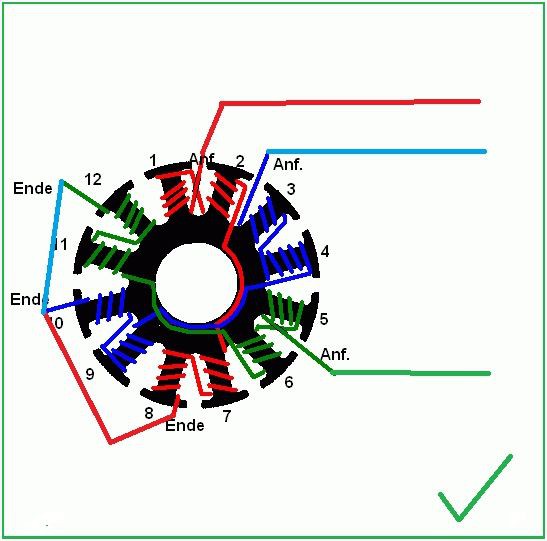
A Propdrive 5060 with lower AWG & more turns would be a better match.
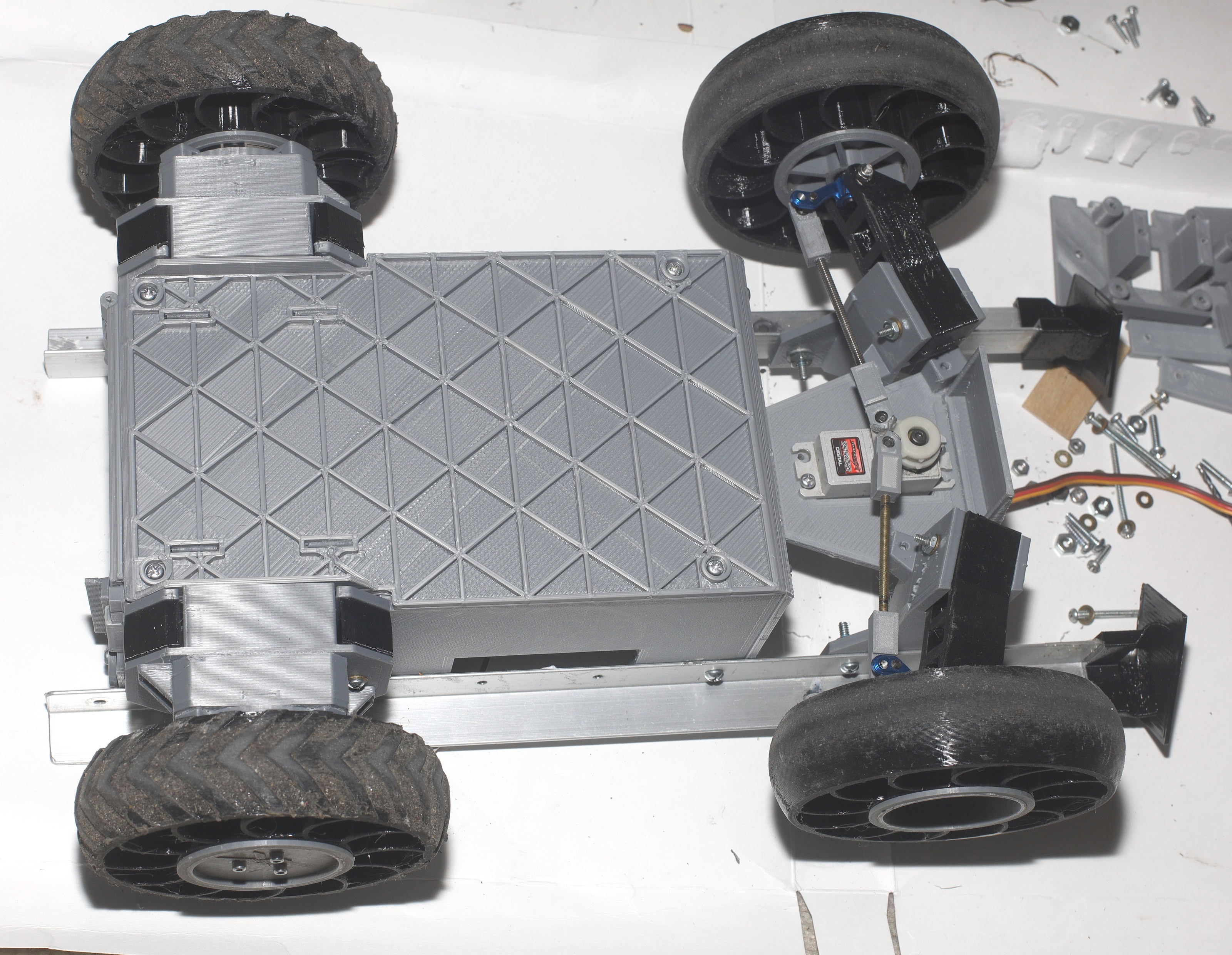
Steering knuckles:

These have to match the wheel base, to achieve ackerman steering.  Lions use

Jazrider Aluminum Front Steering Knuckle Upright For Tamiya RC CW01/Lunch Box


from fleebay & size the wheel base to within 1" of a lunchbox.  
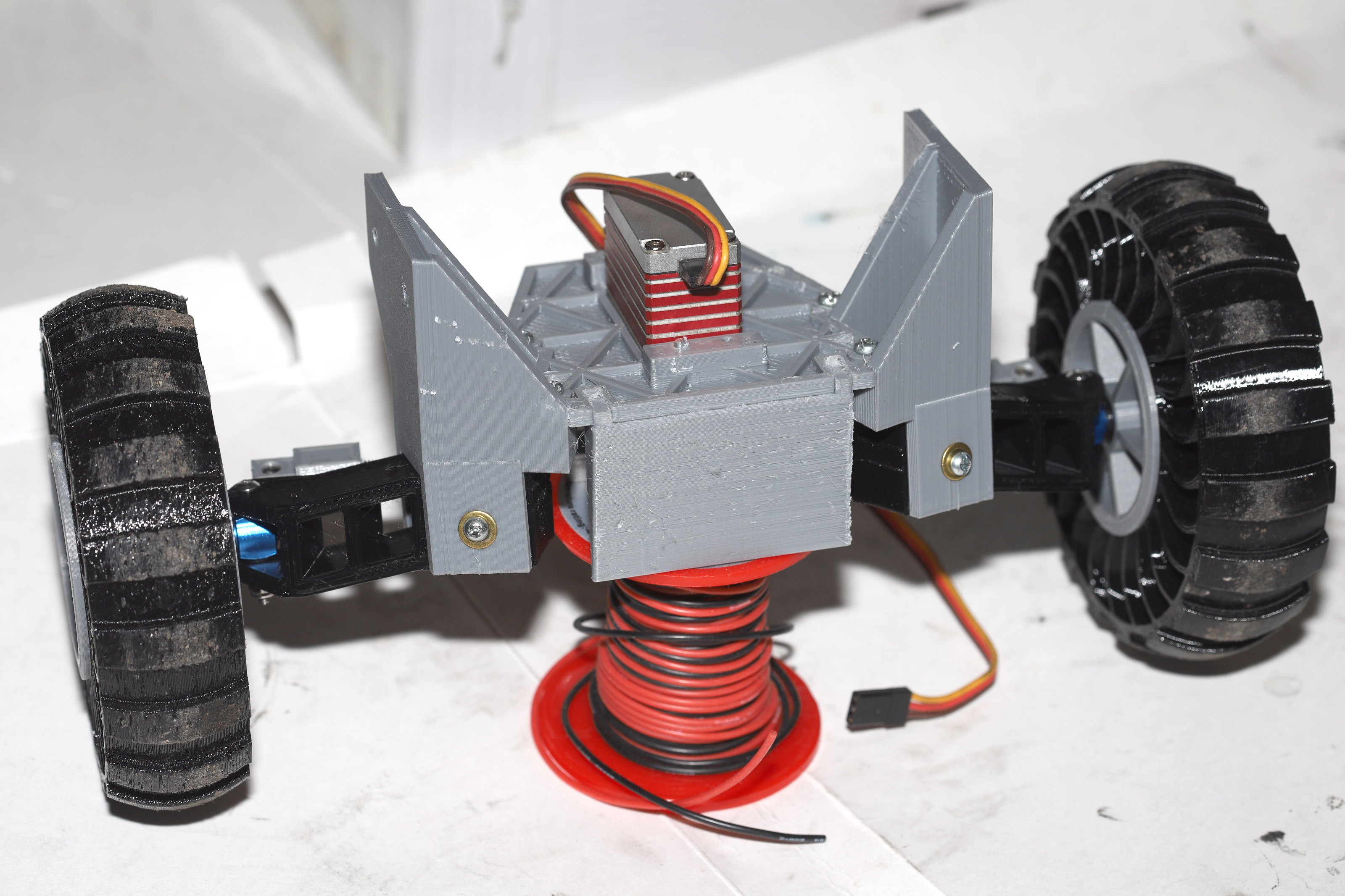
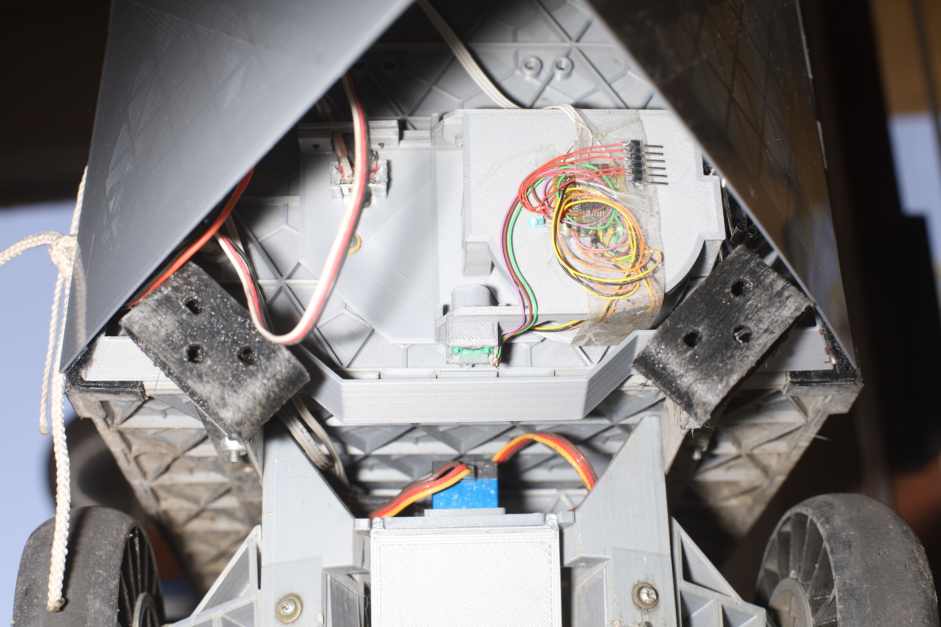
Steering servo:

The lion kingdom uses discontinued trackstar brushless servos with servo savers.  Brushless is required to get any life out of them.

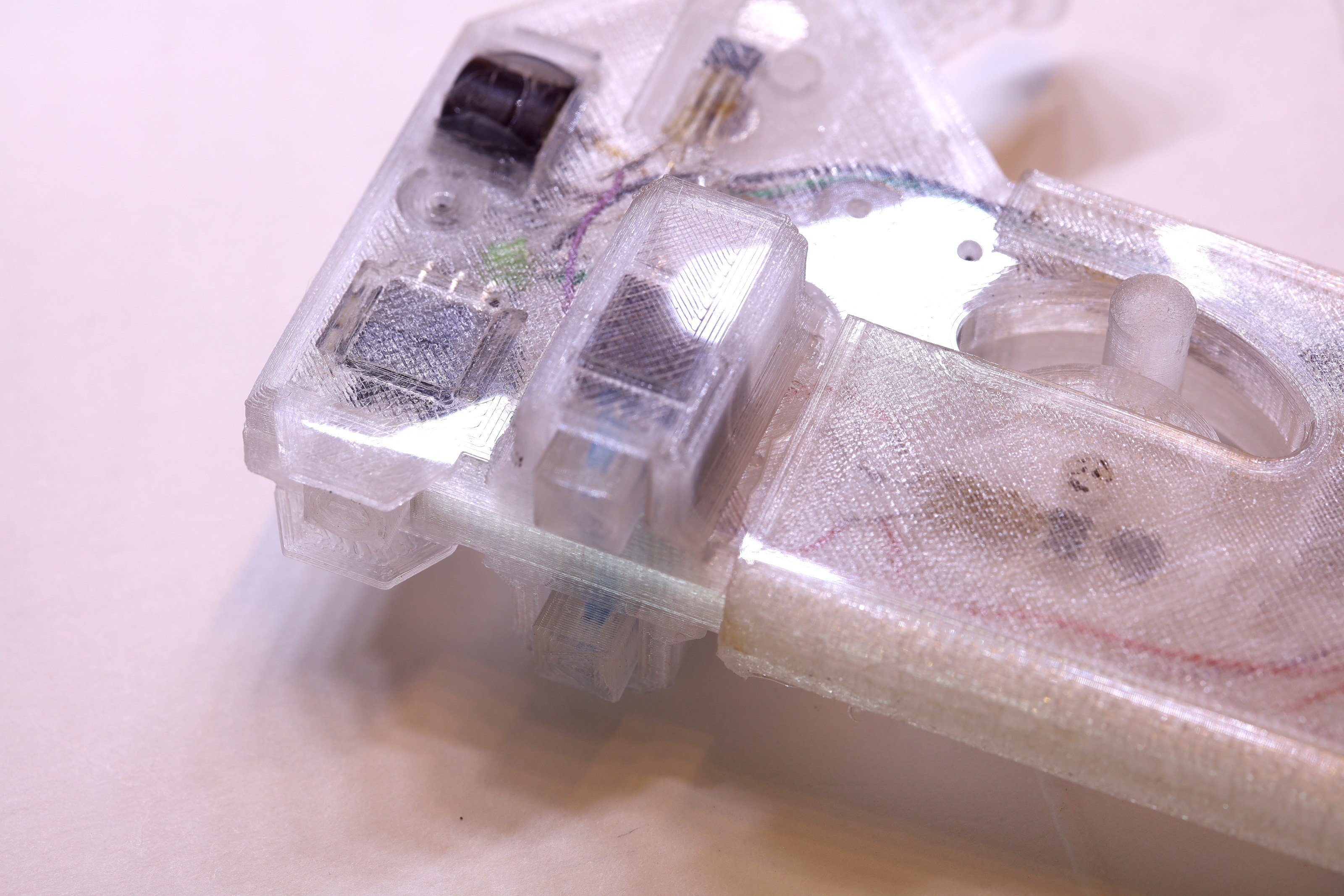
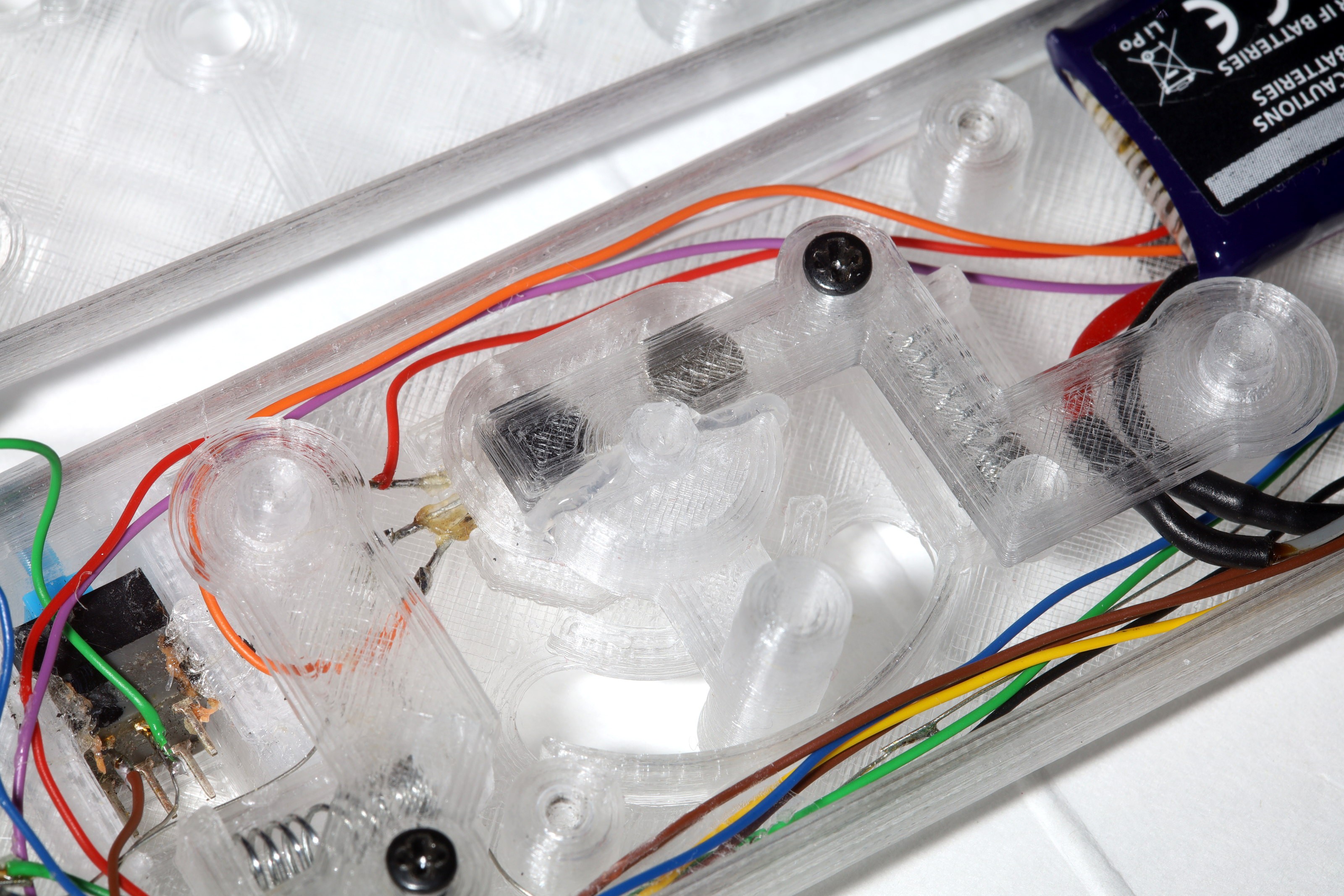
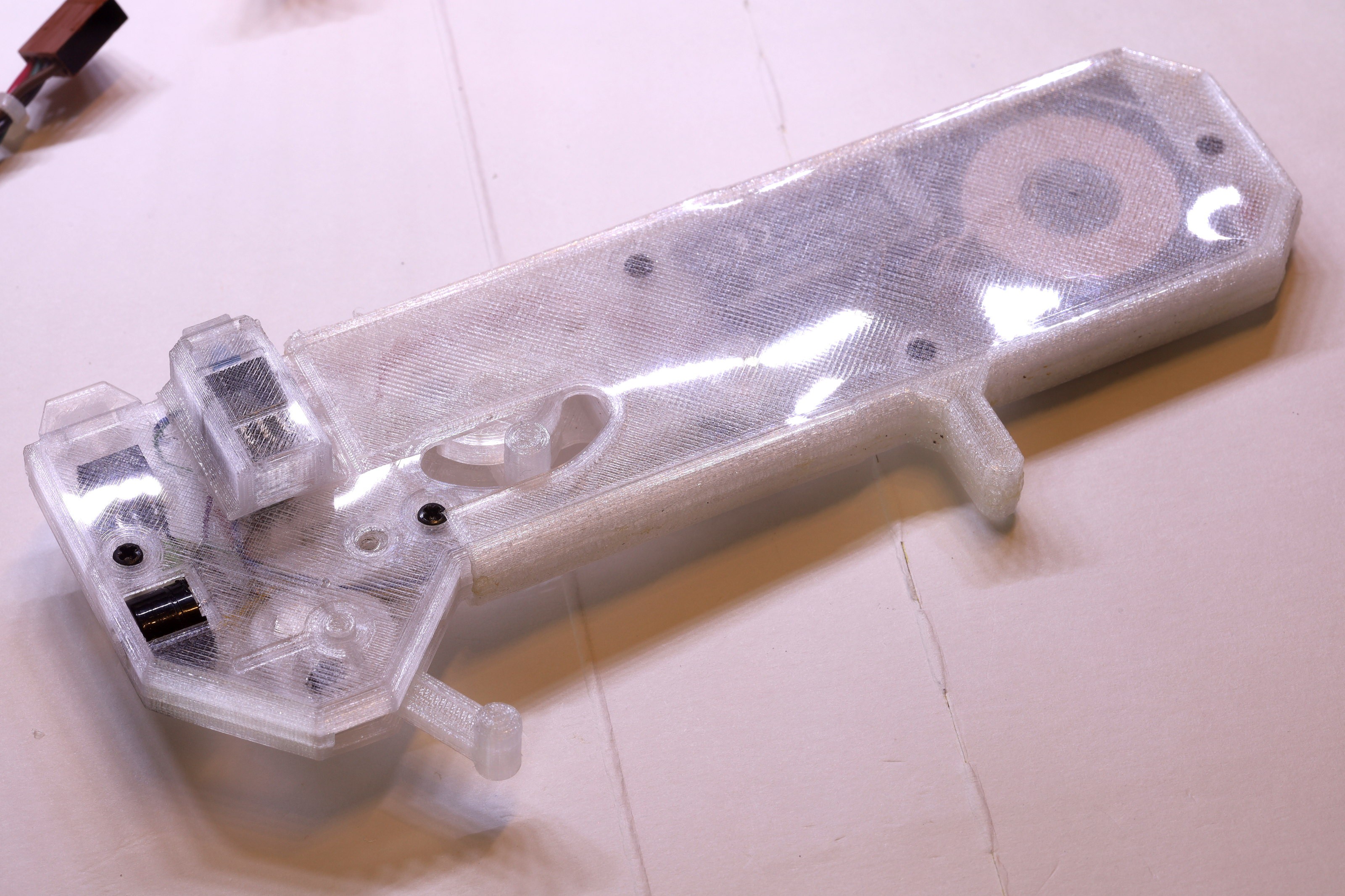
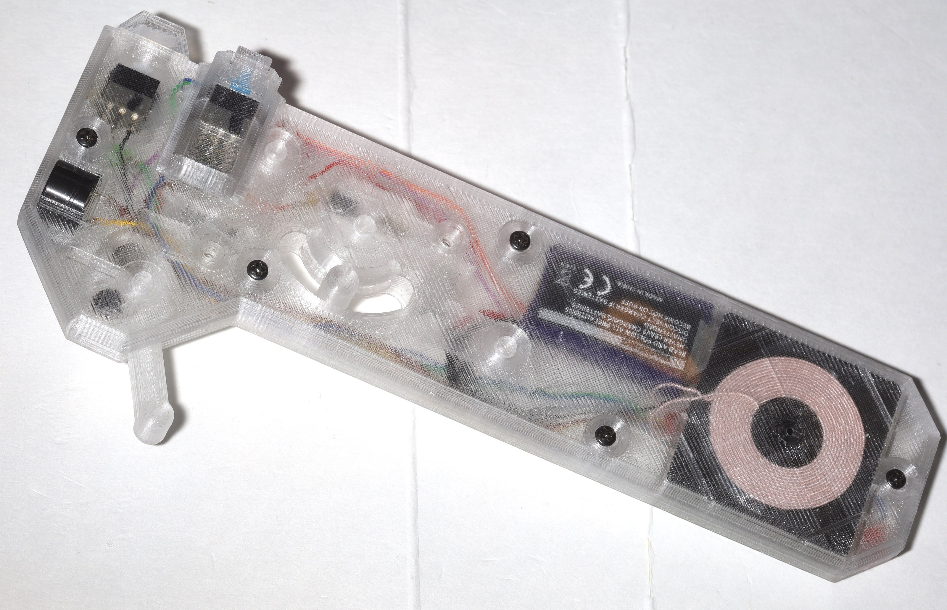
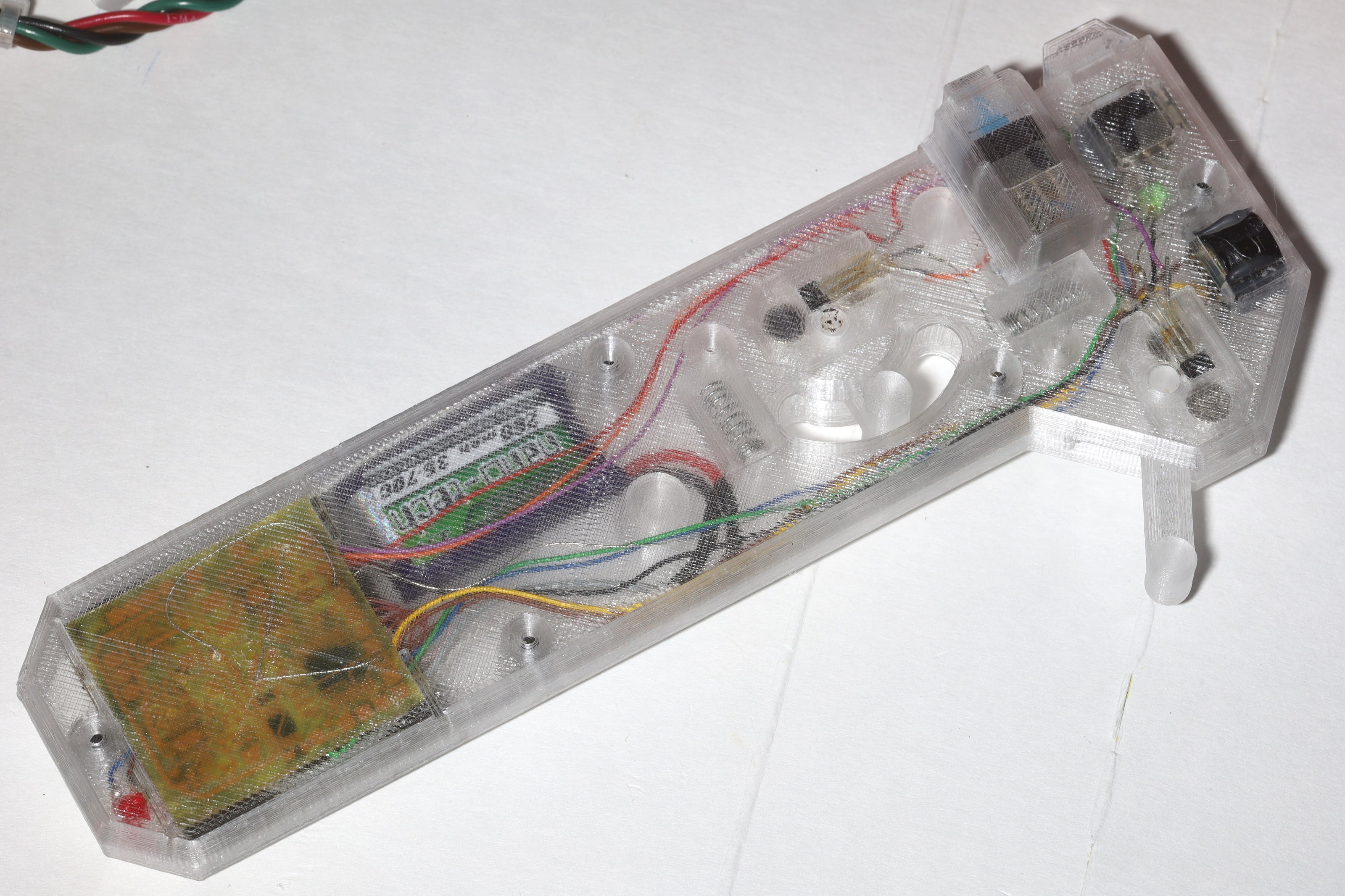
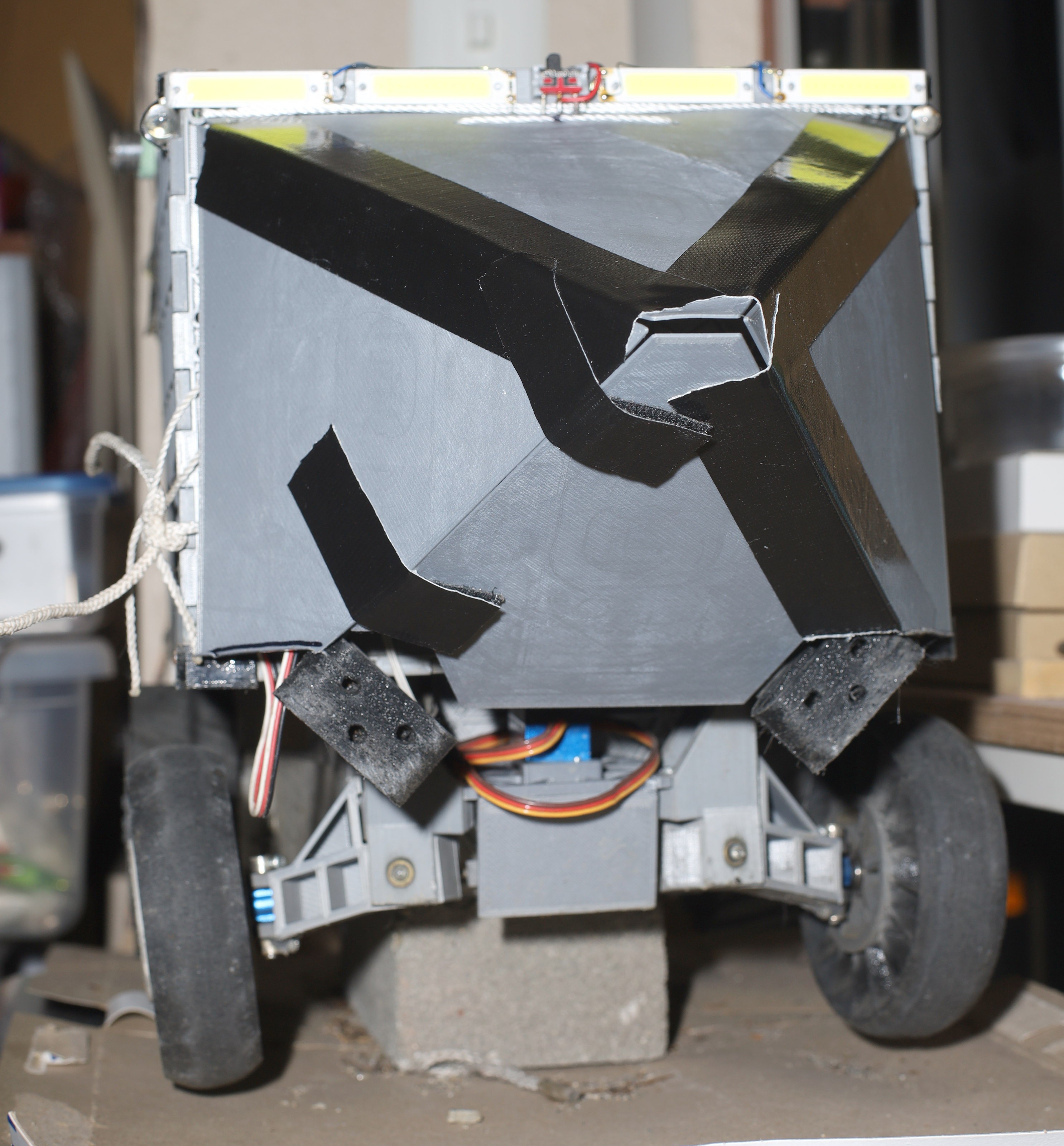
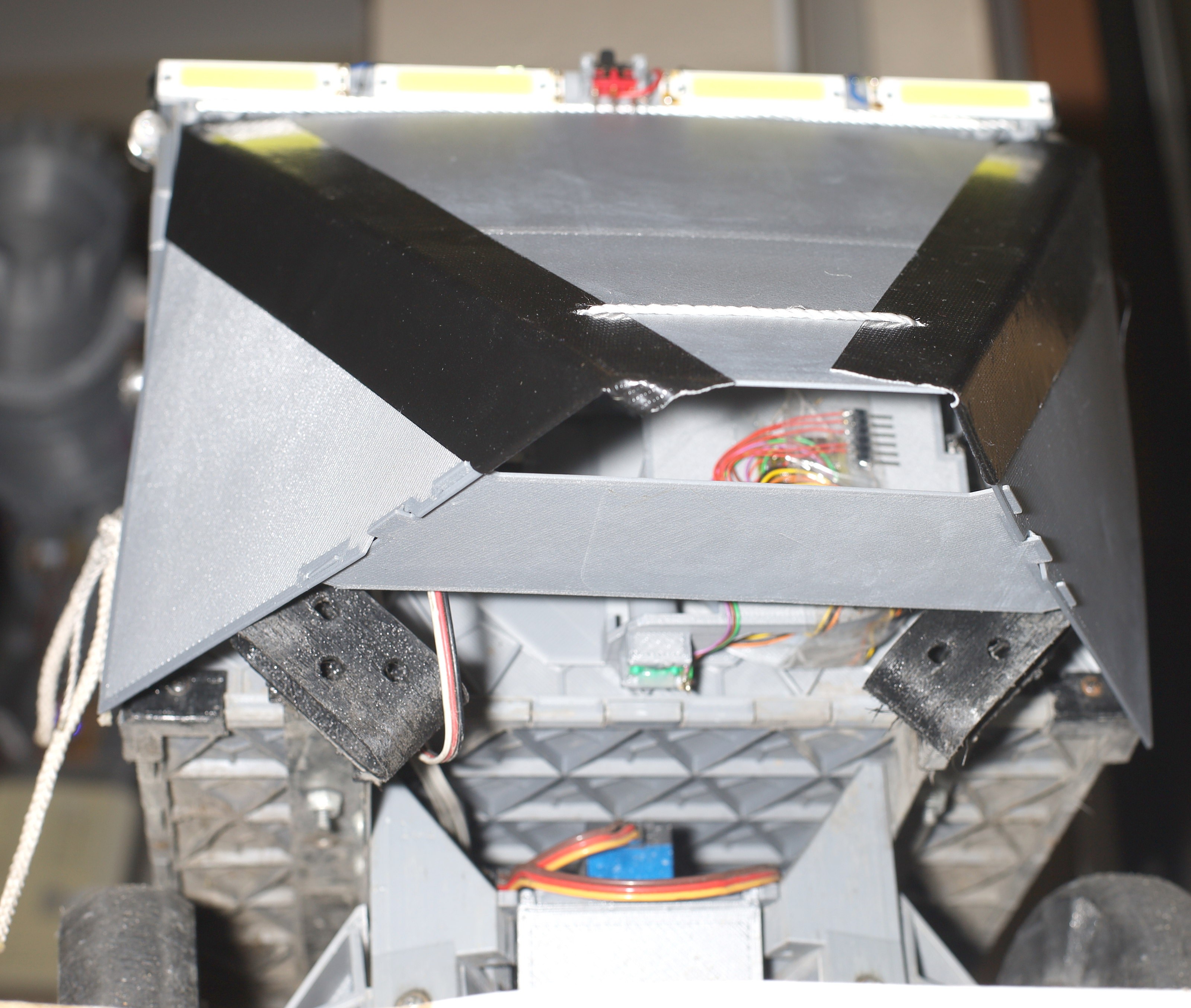
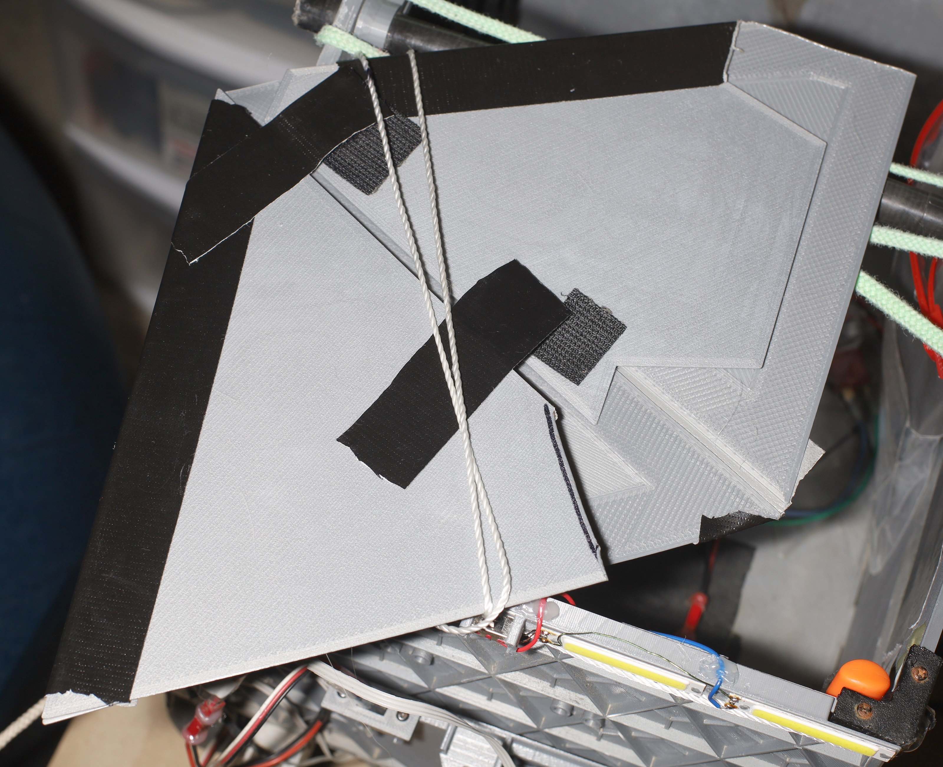
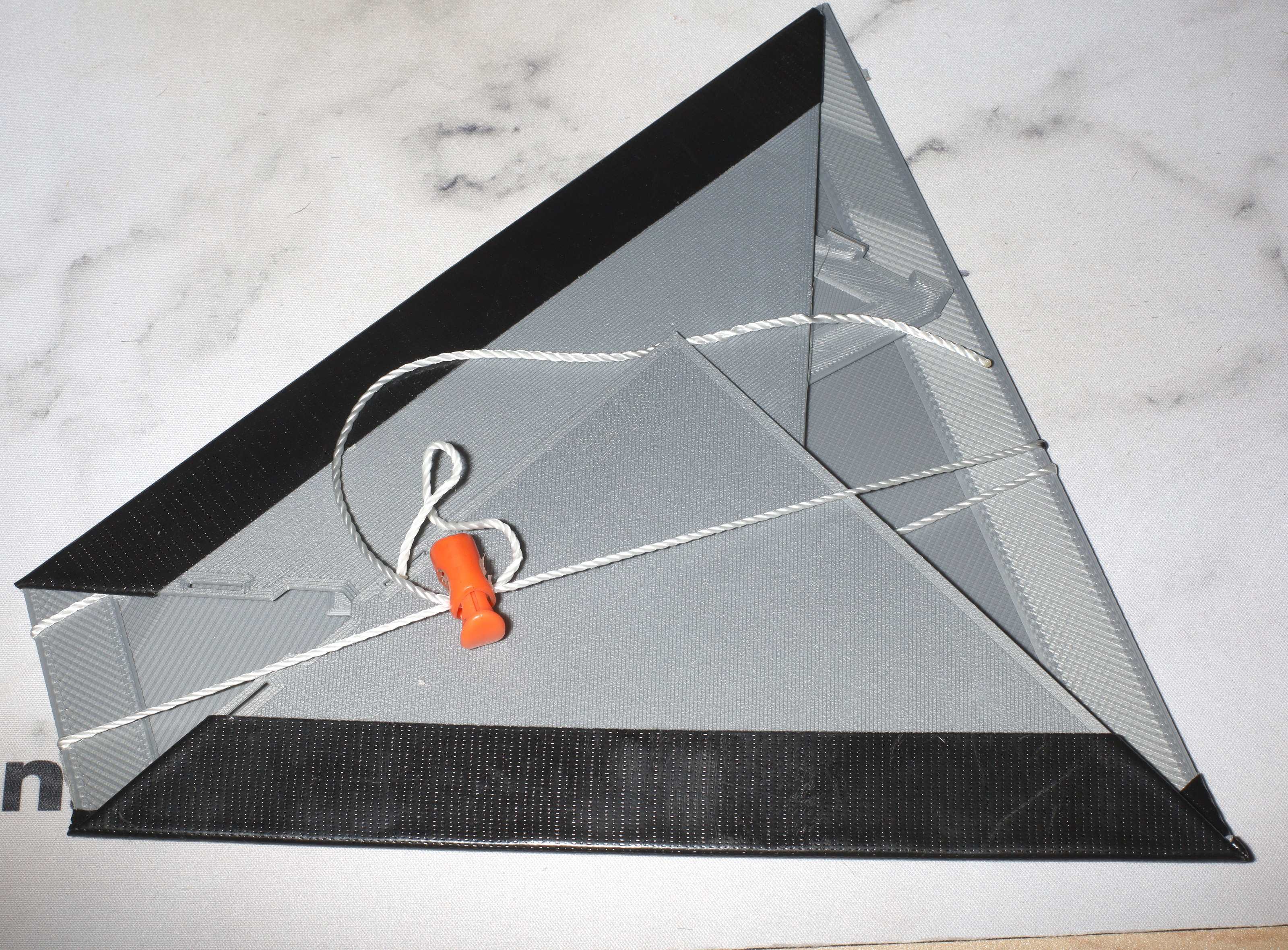
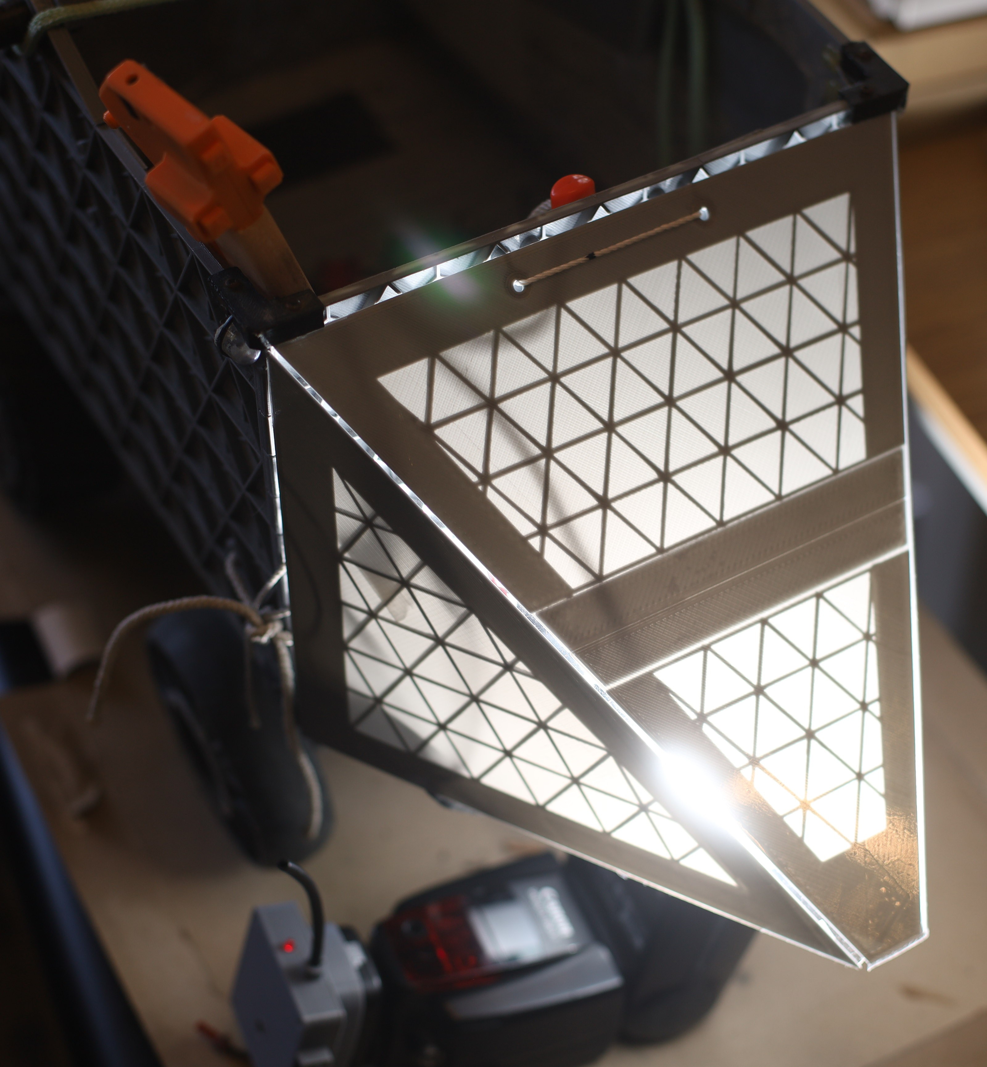
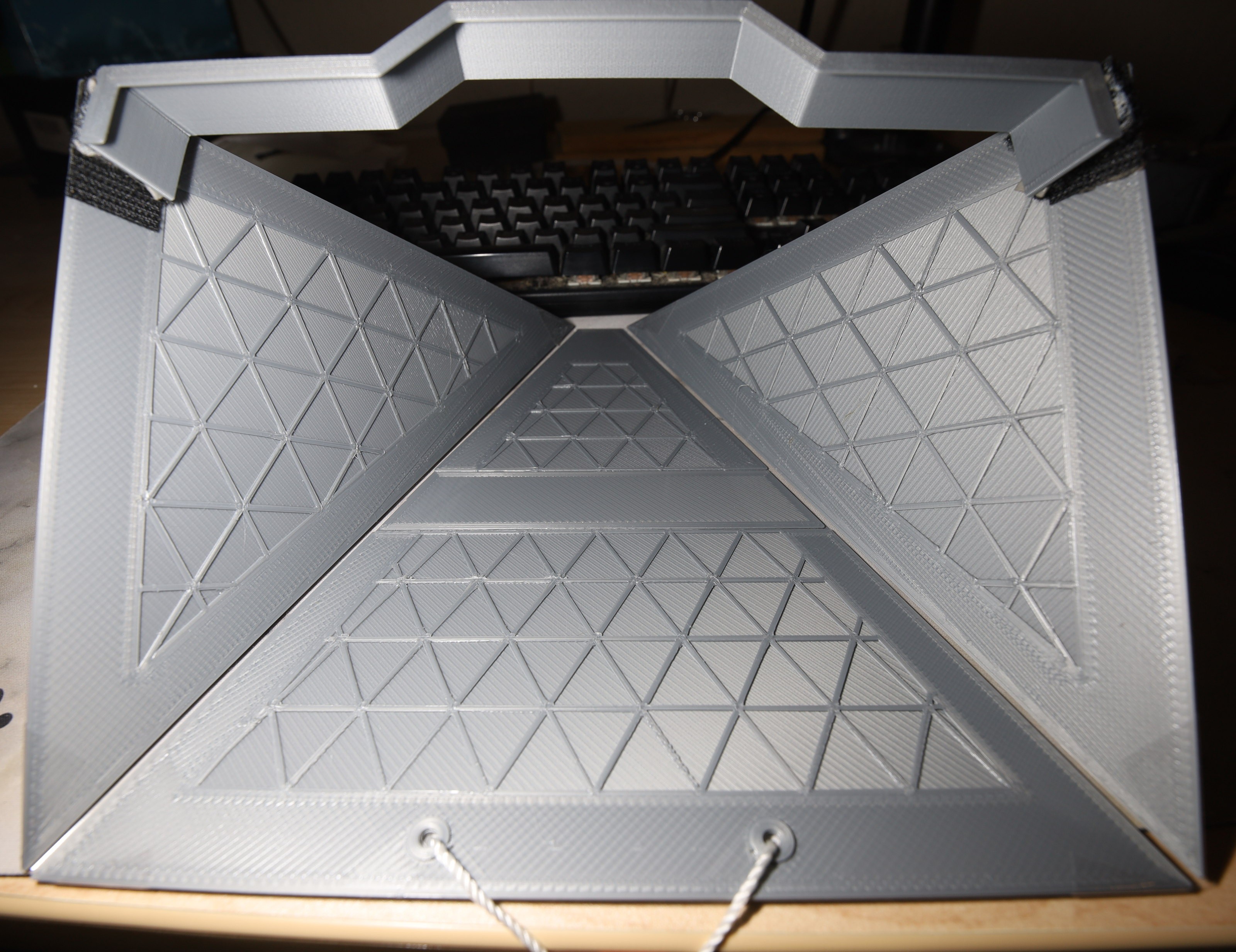
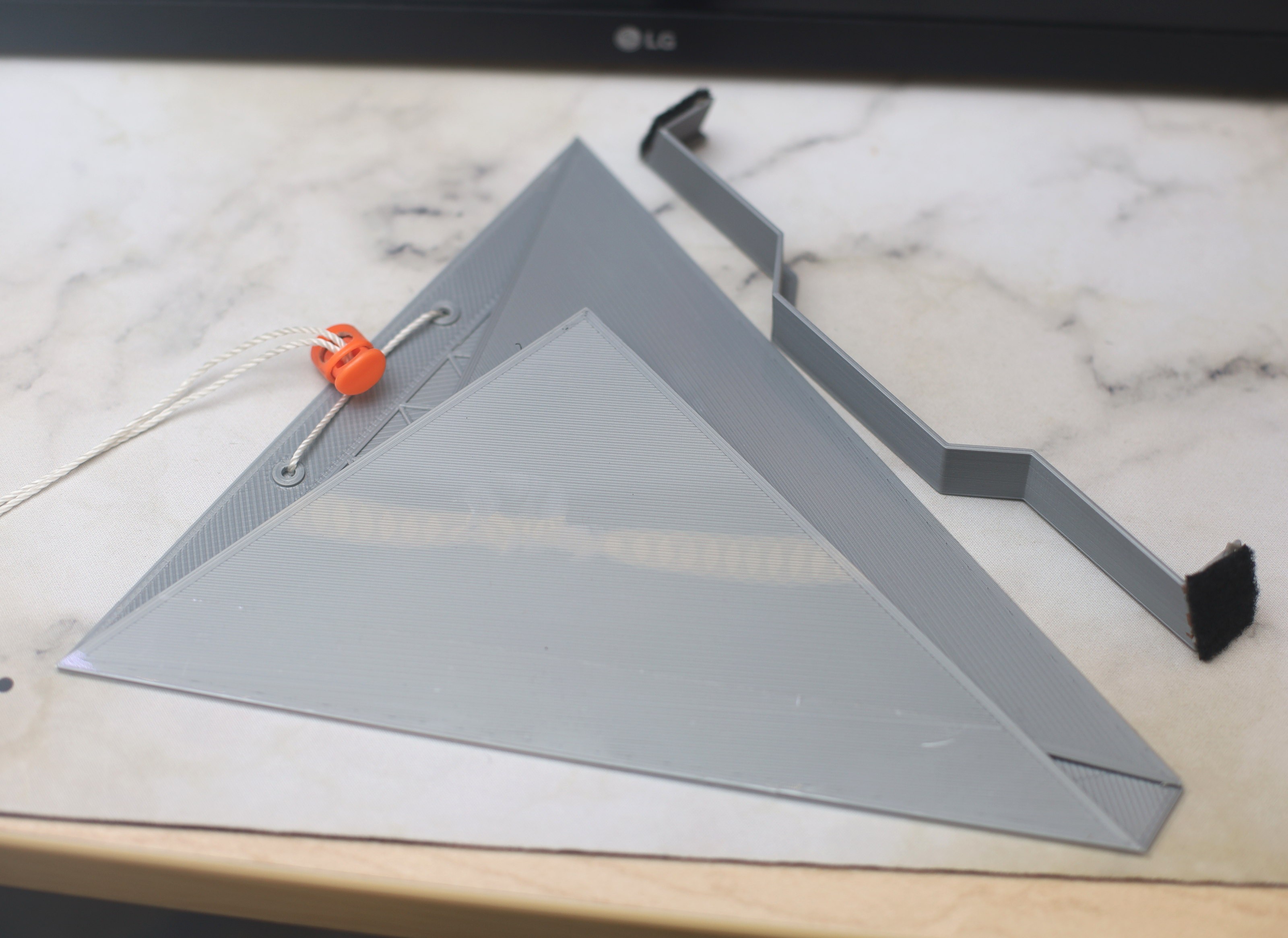
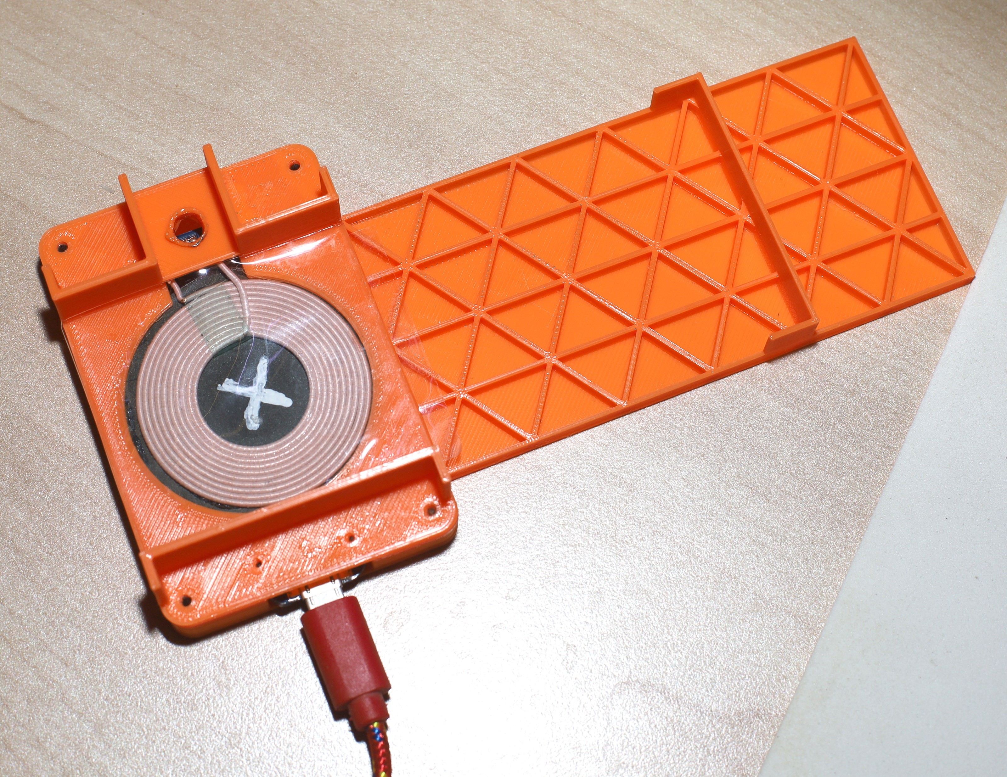
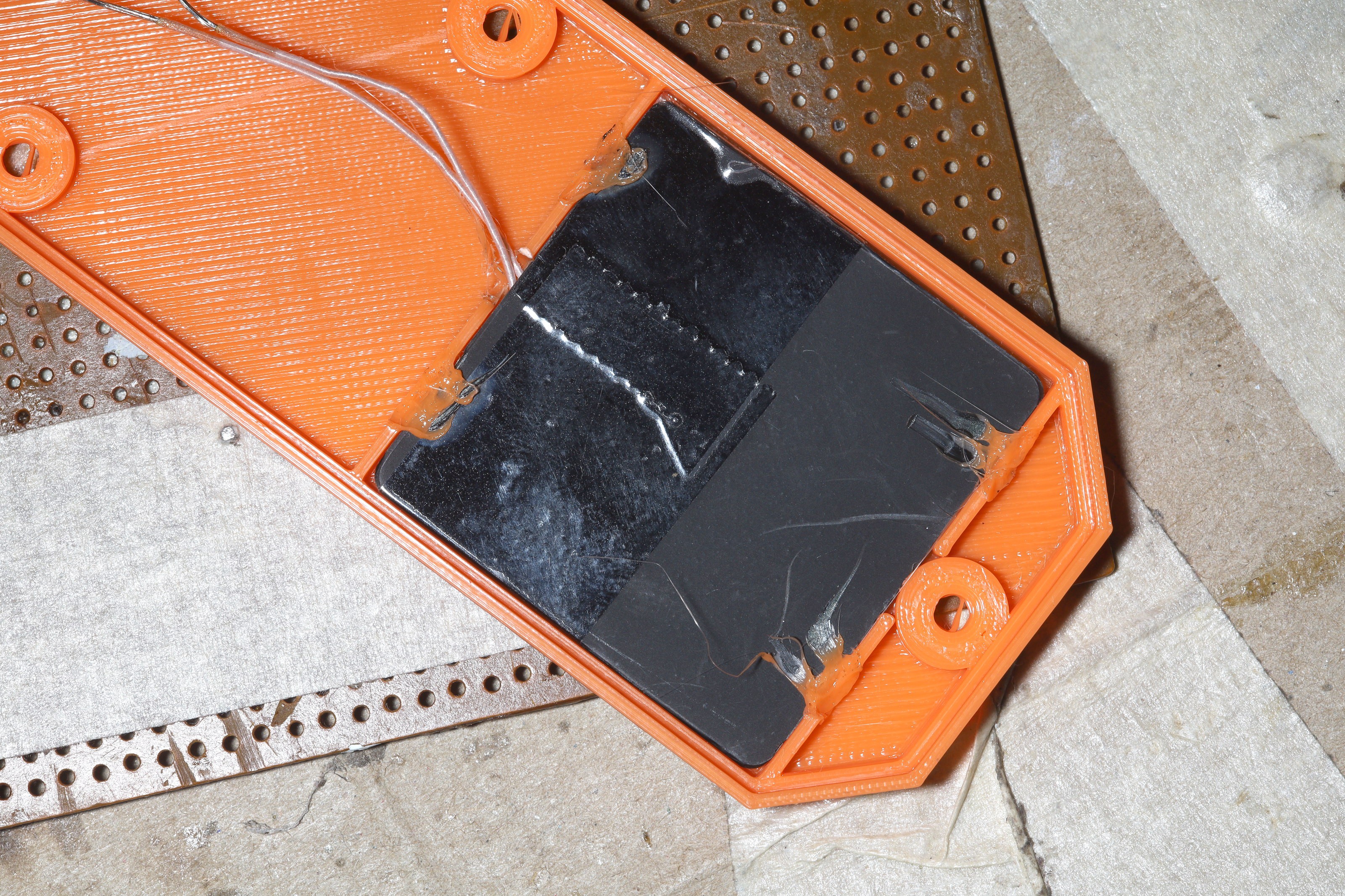
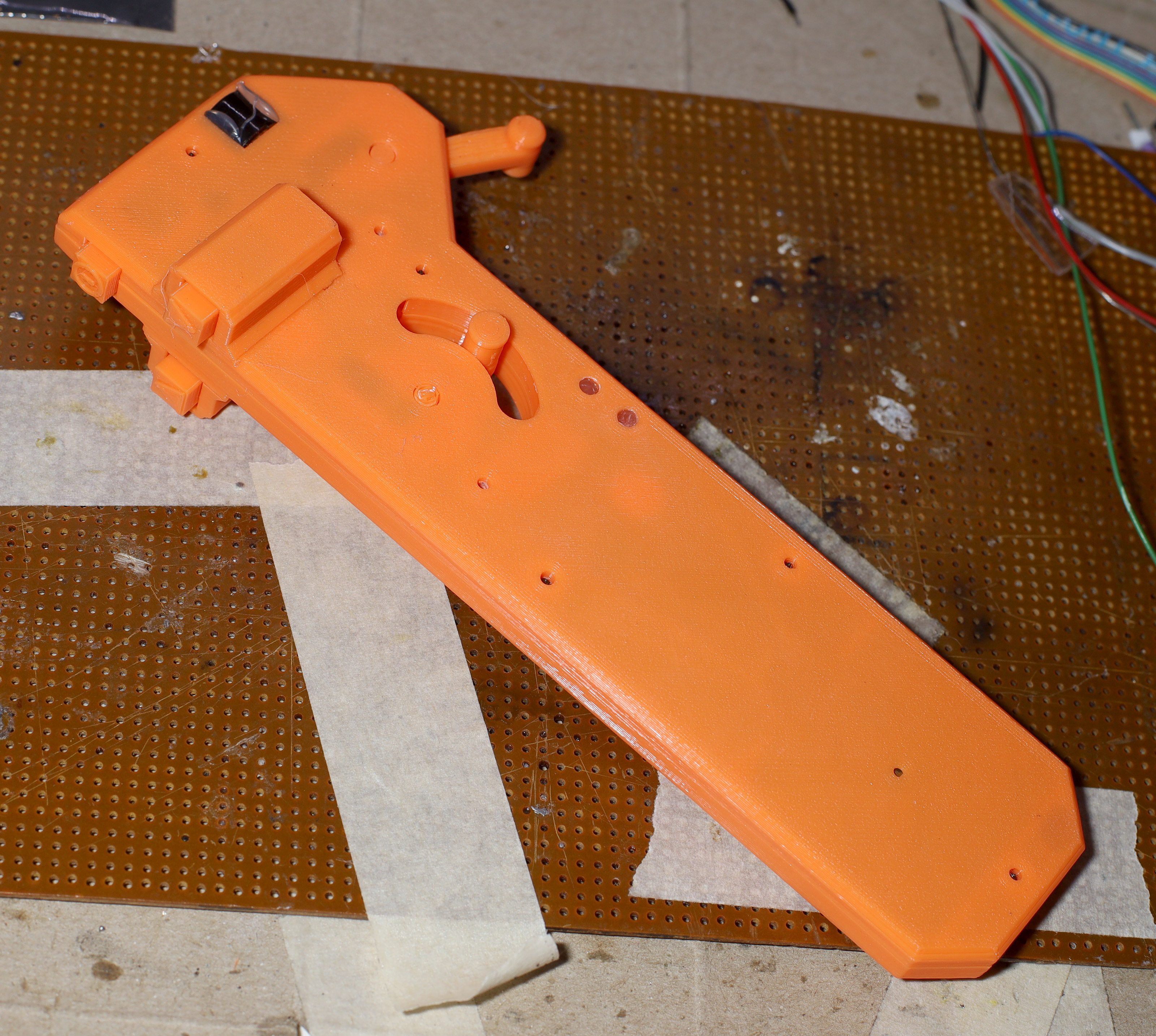
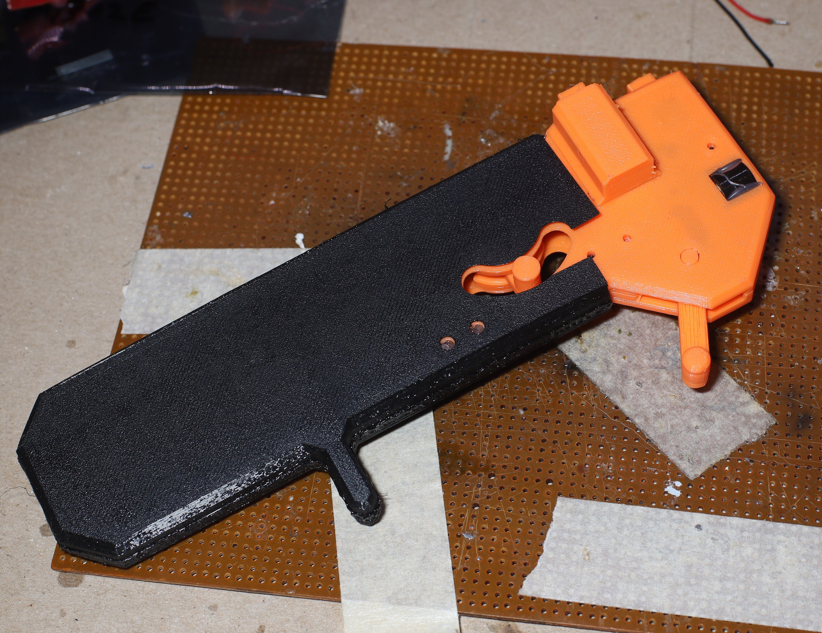
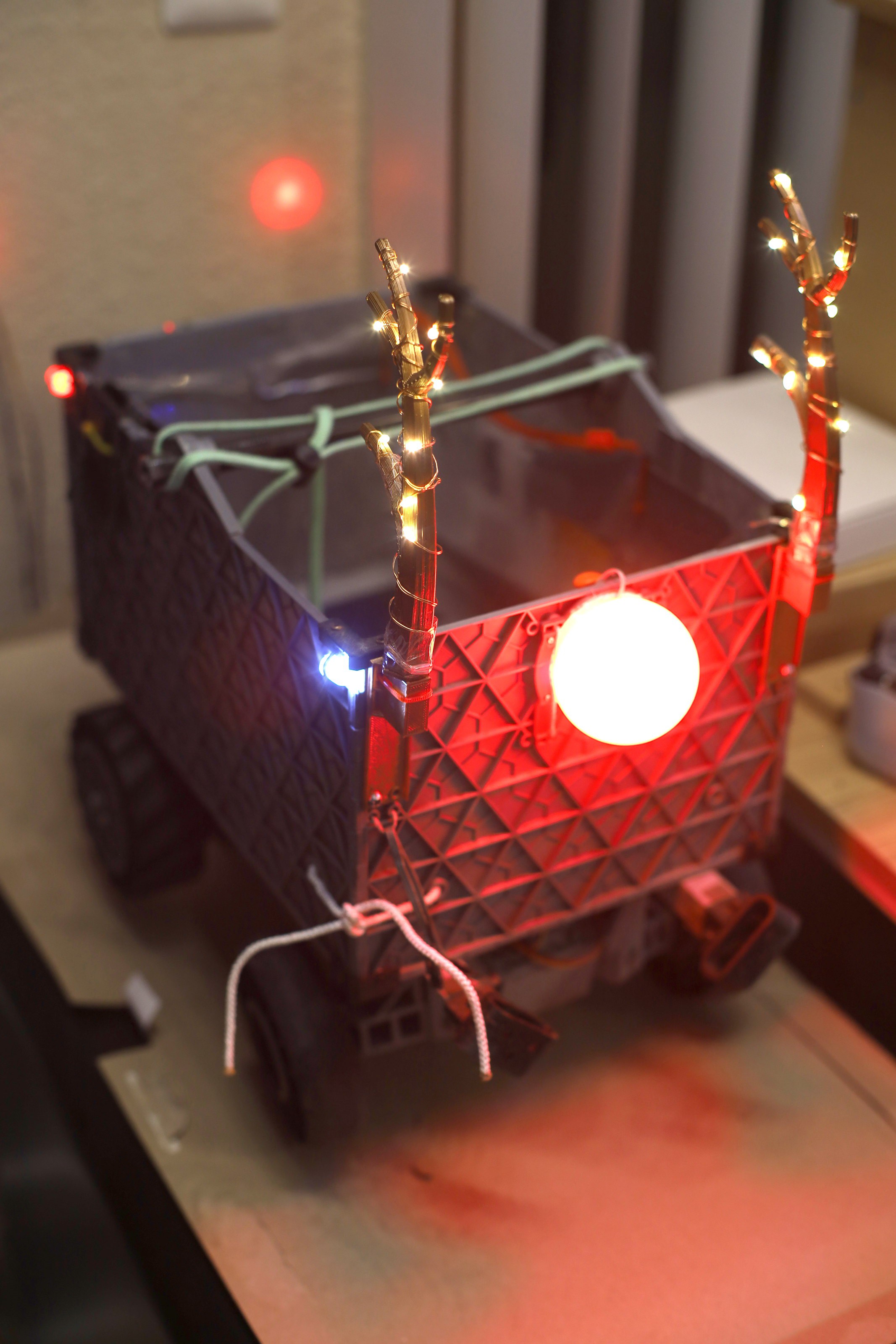
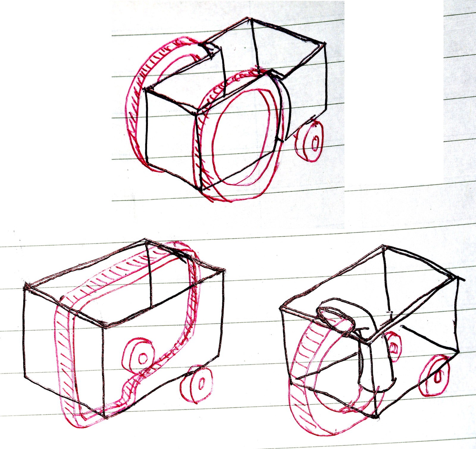
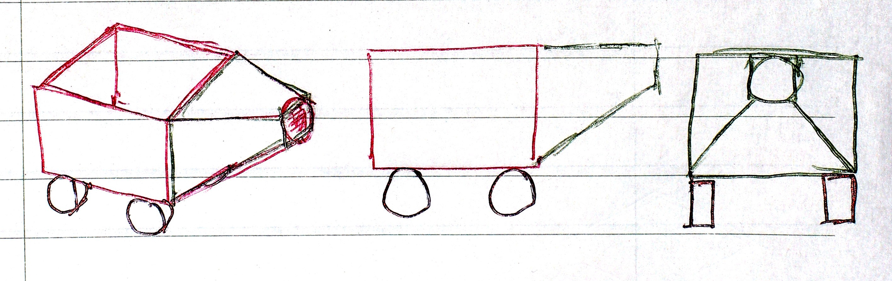
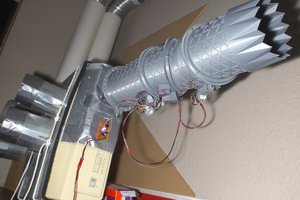
The 3 mane components are the steering module, traction module, & the coroplastic container.  They're held together by  aluminum angle rods.

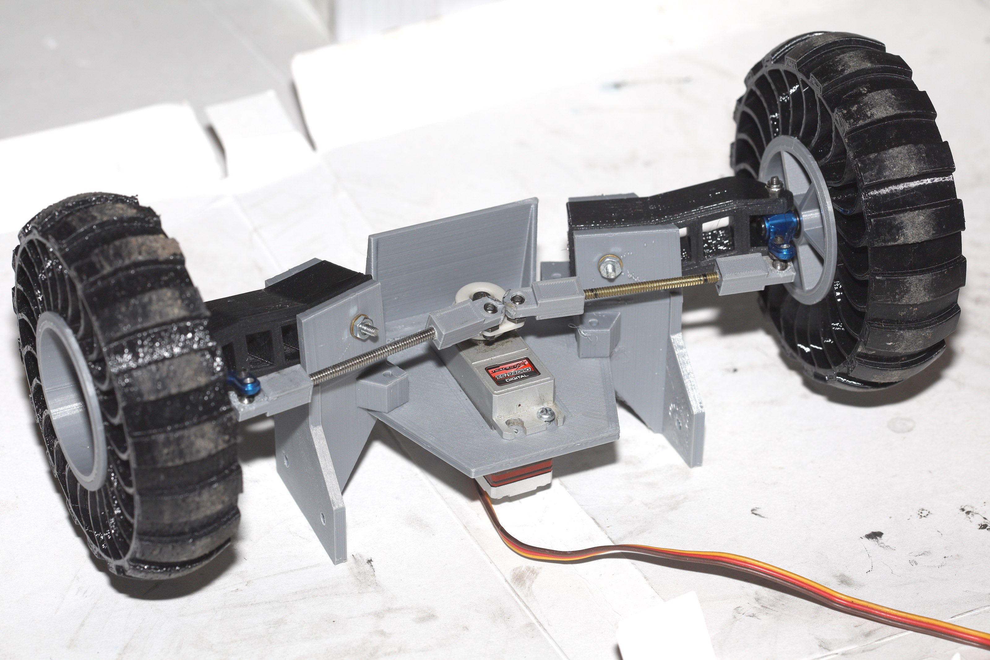
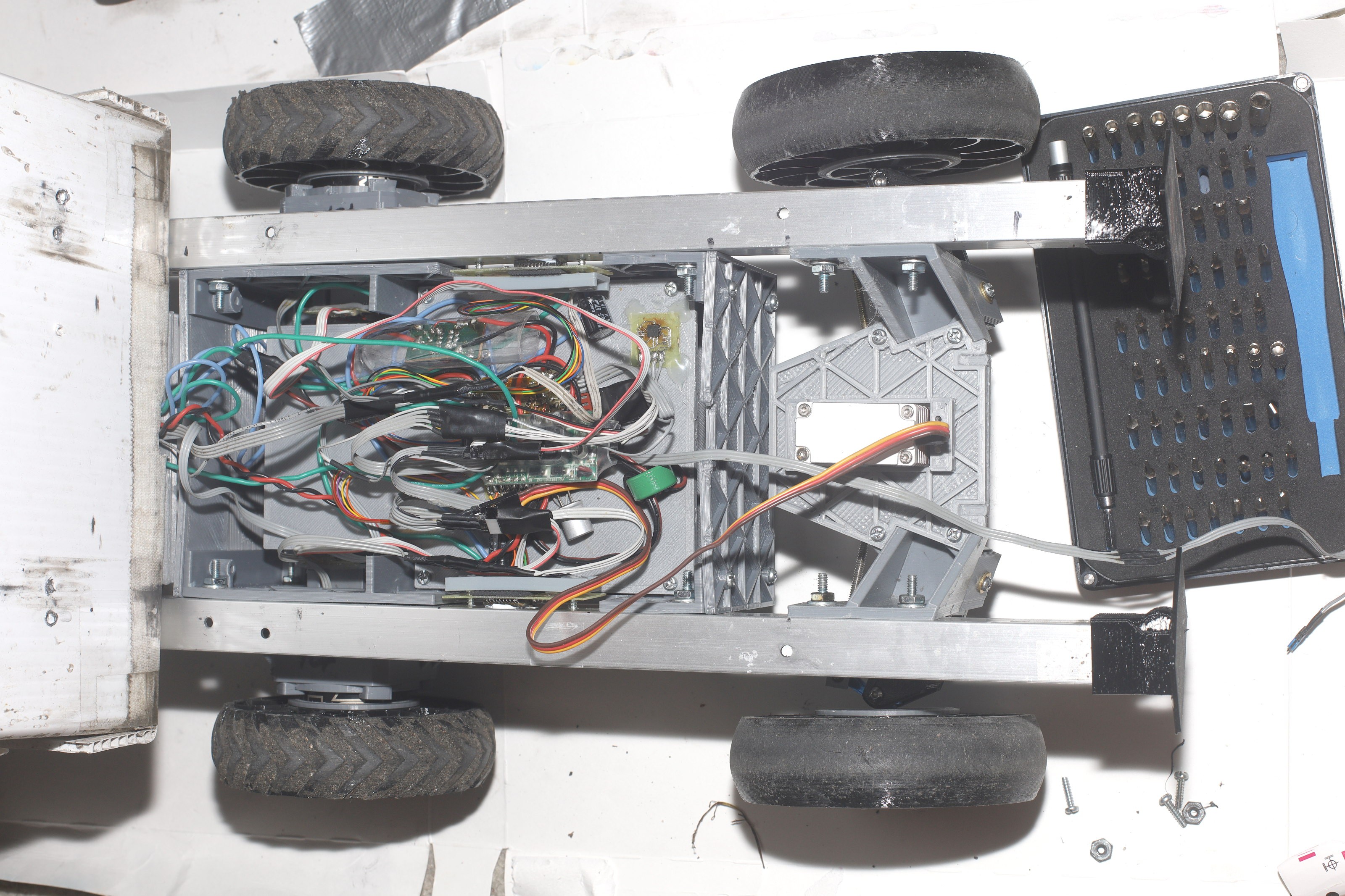
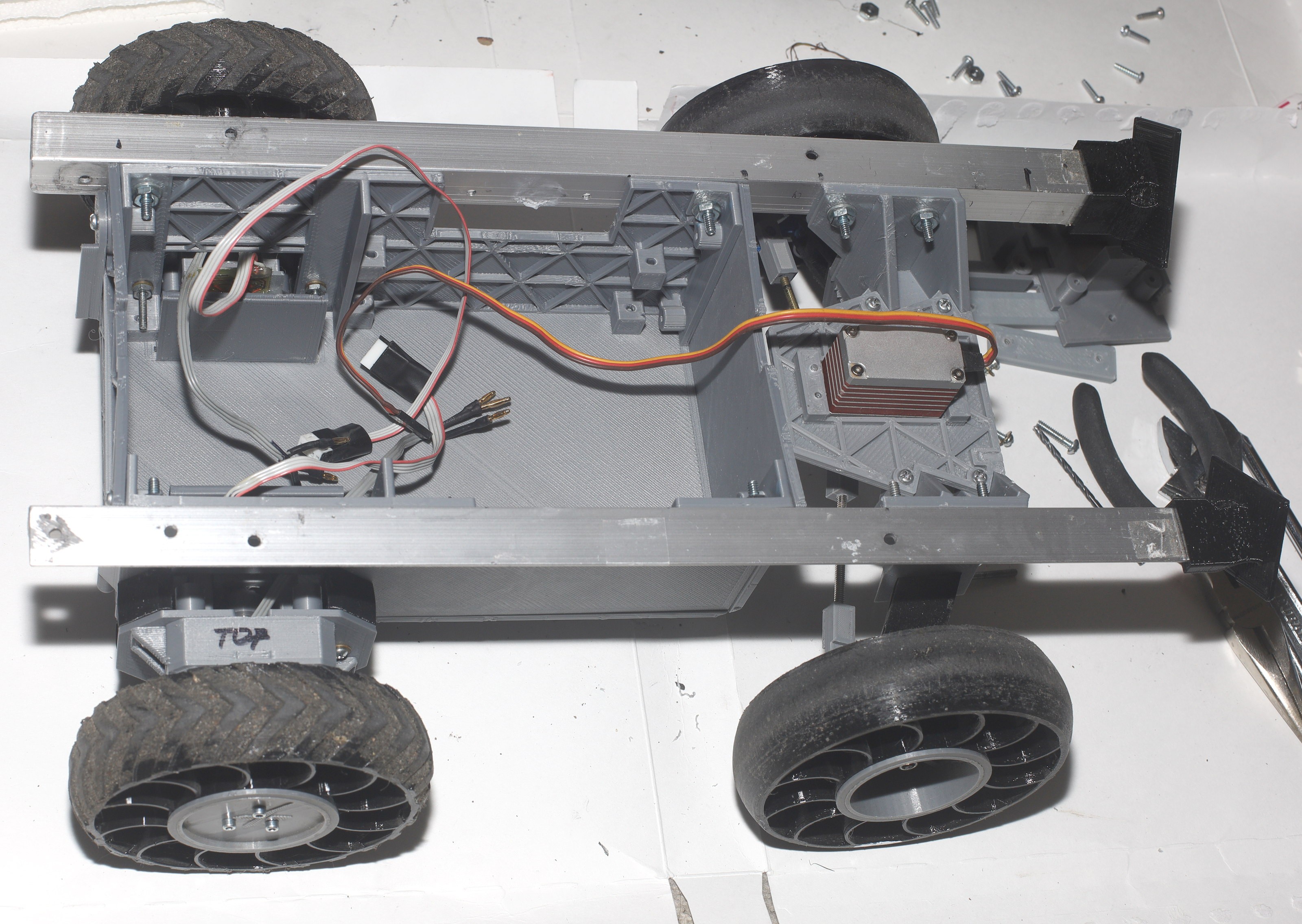
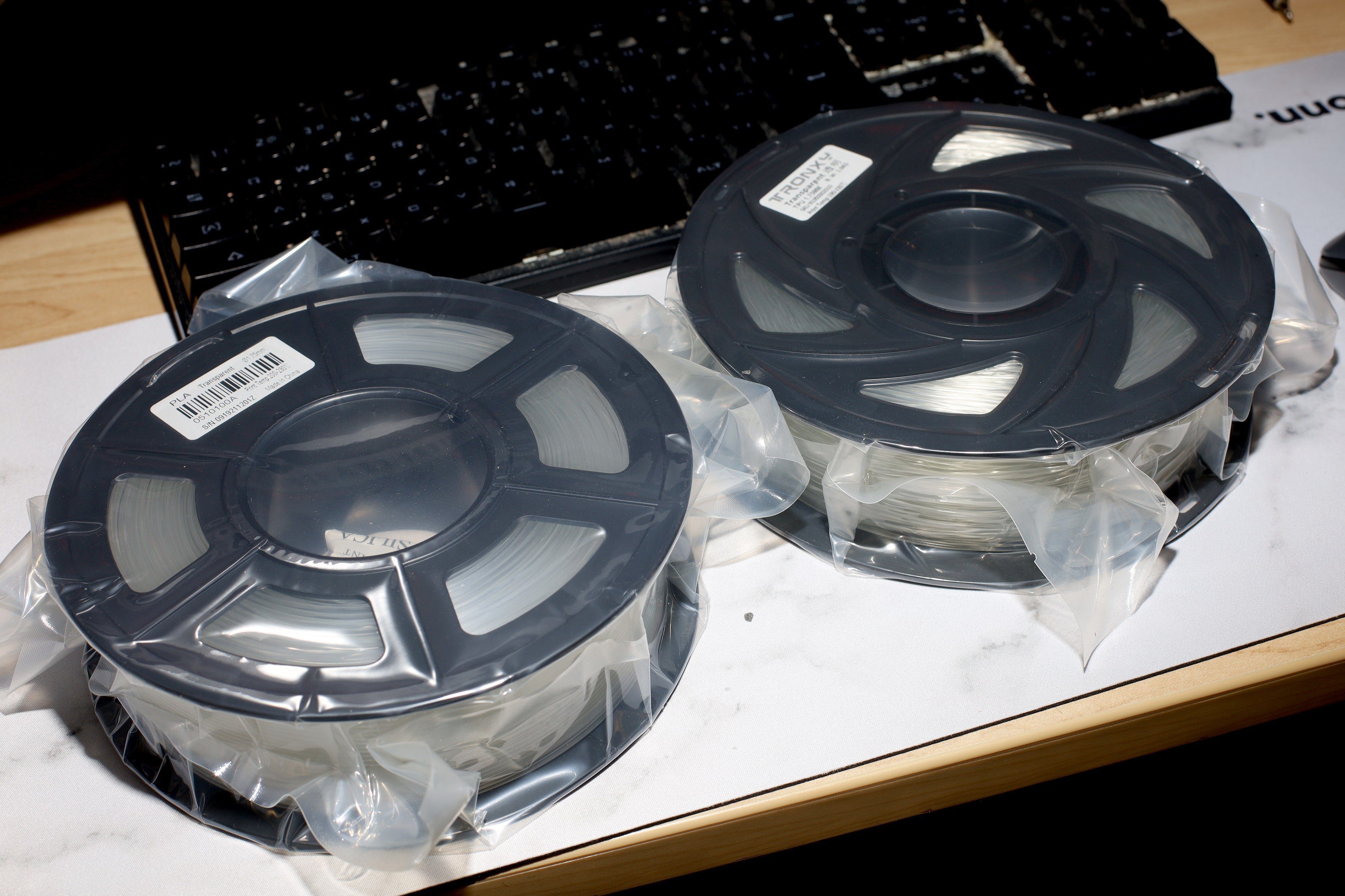
The tires are 3D printed out of TPU for a lot less money than Chinese ones.

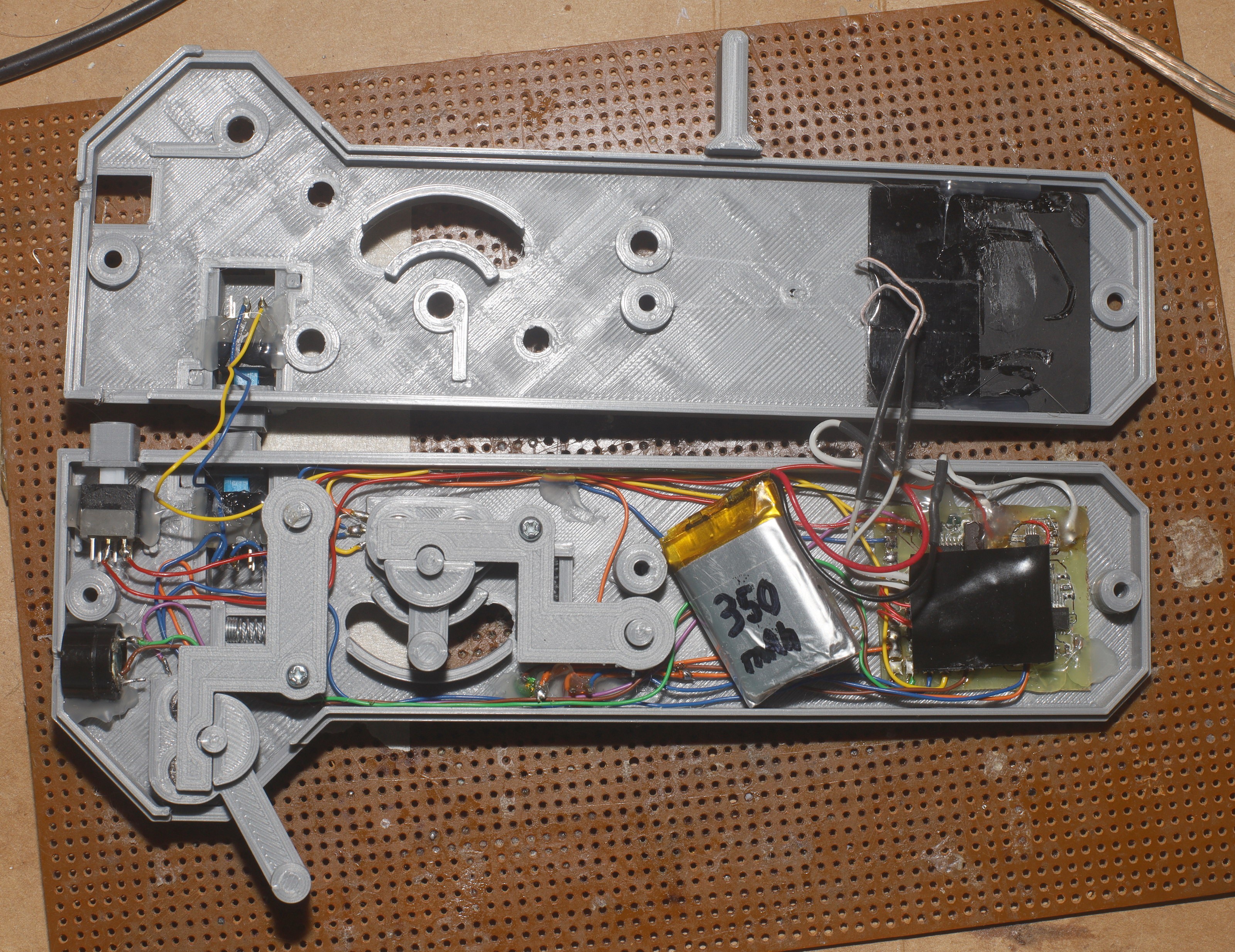
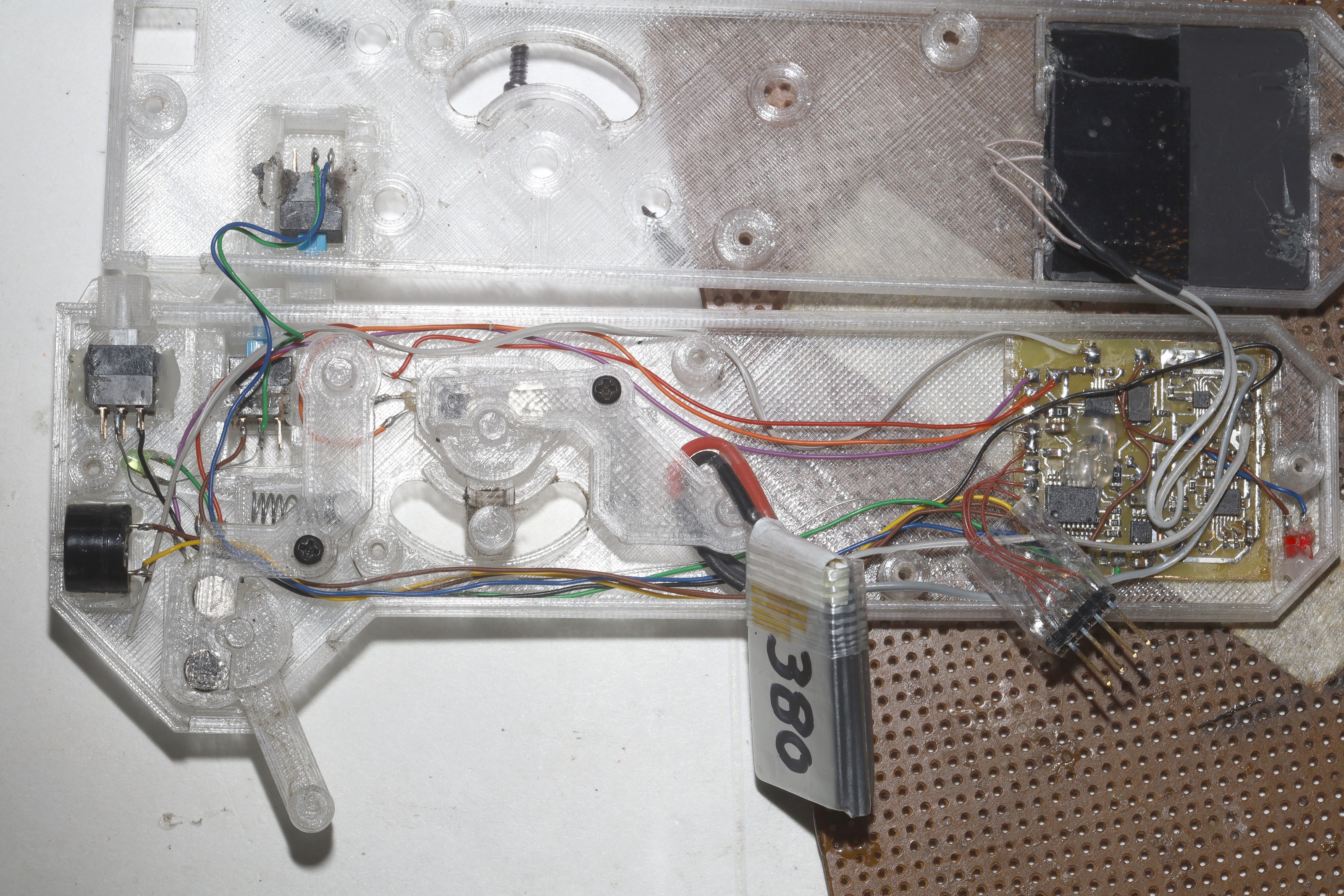
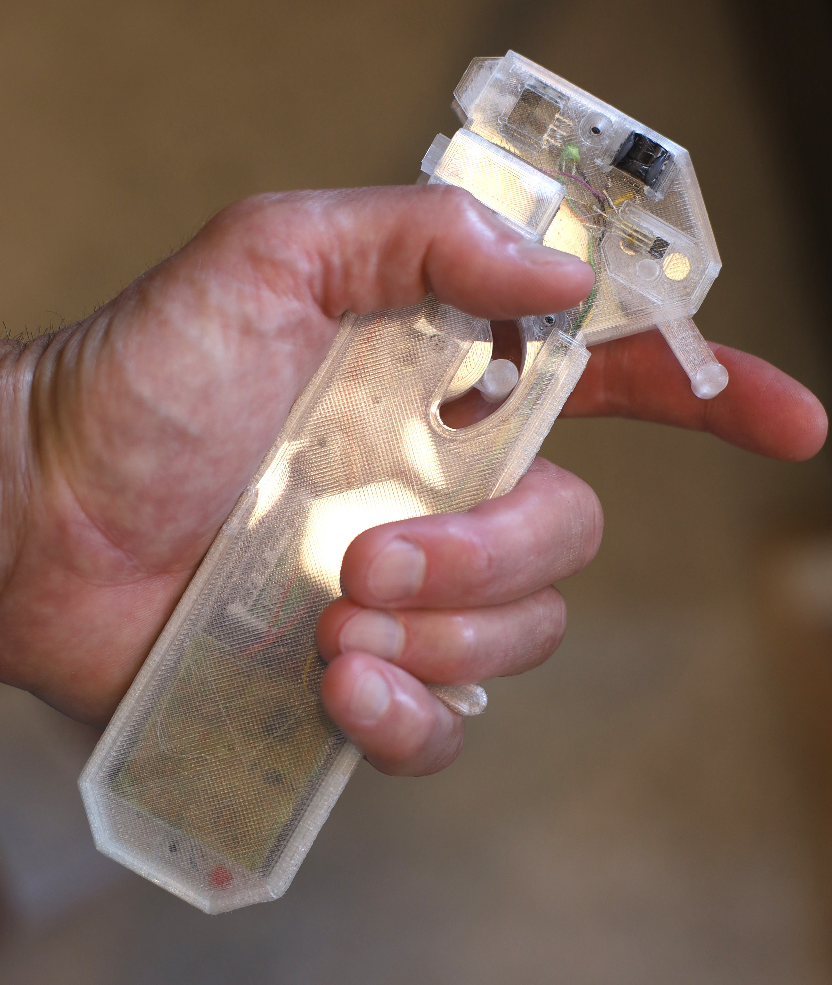
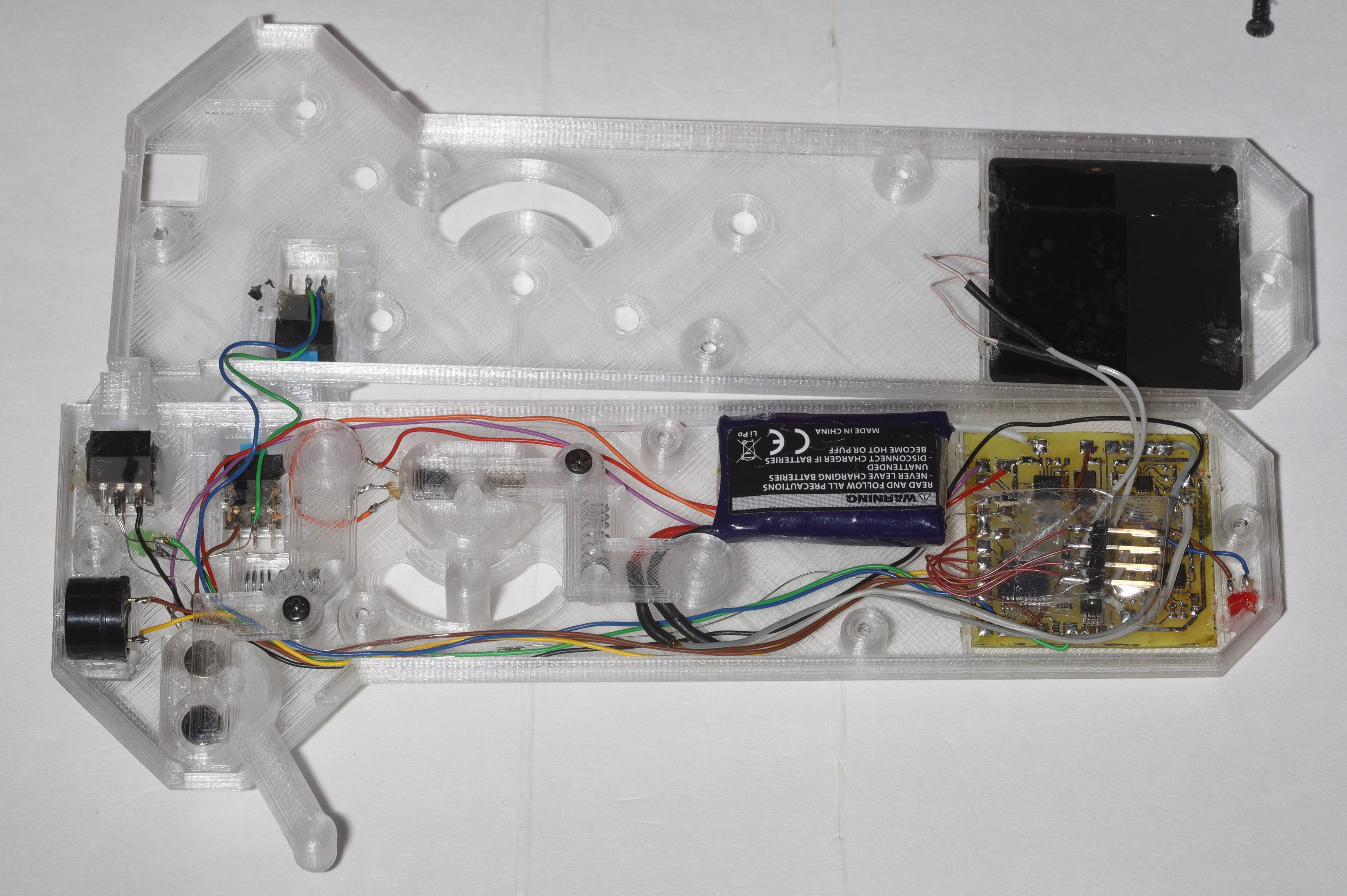
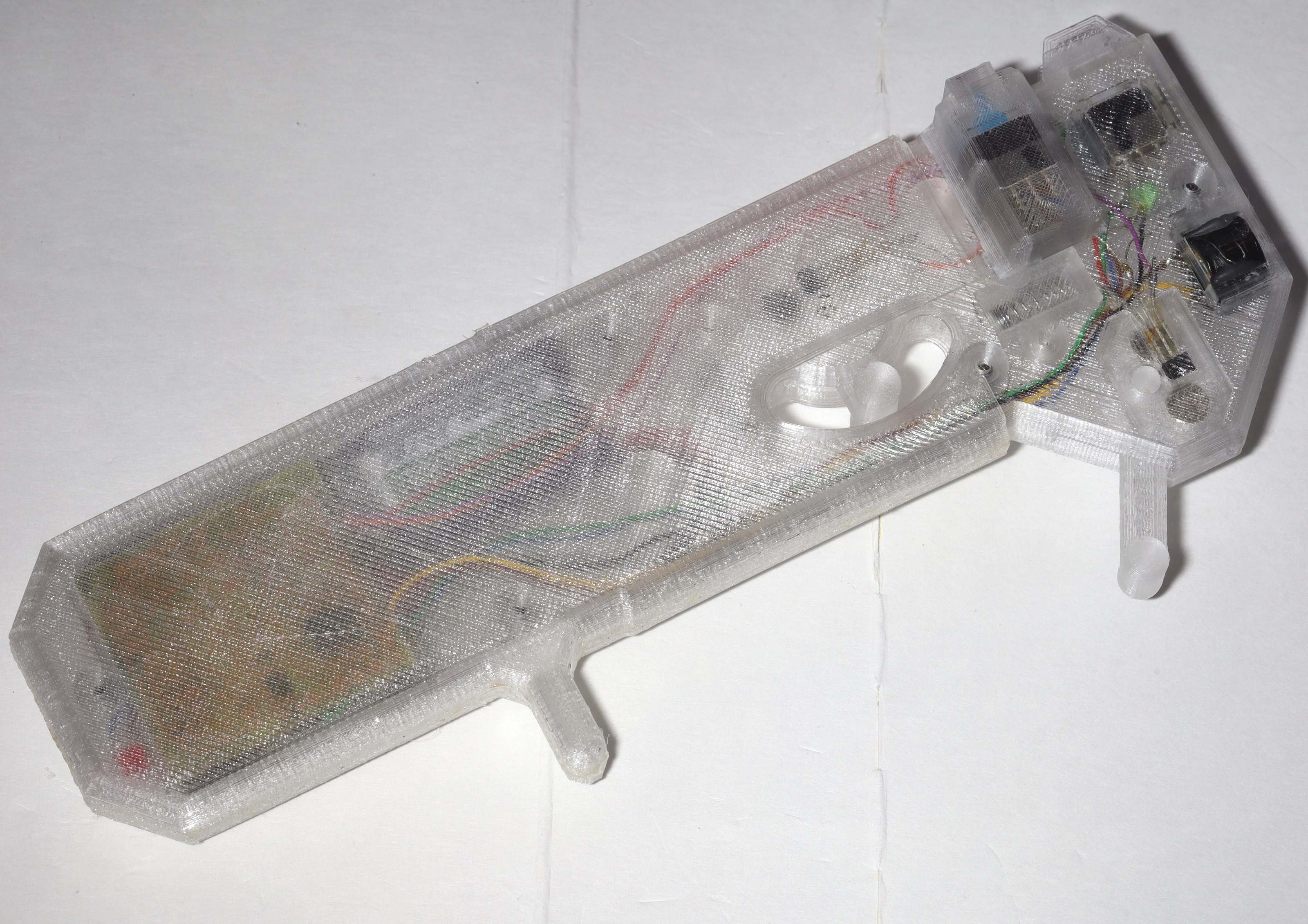
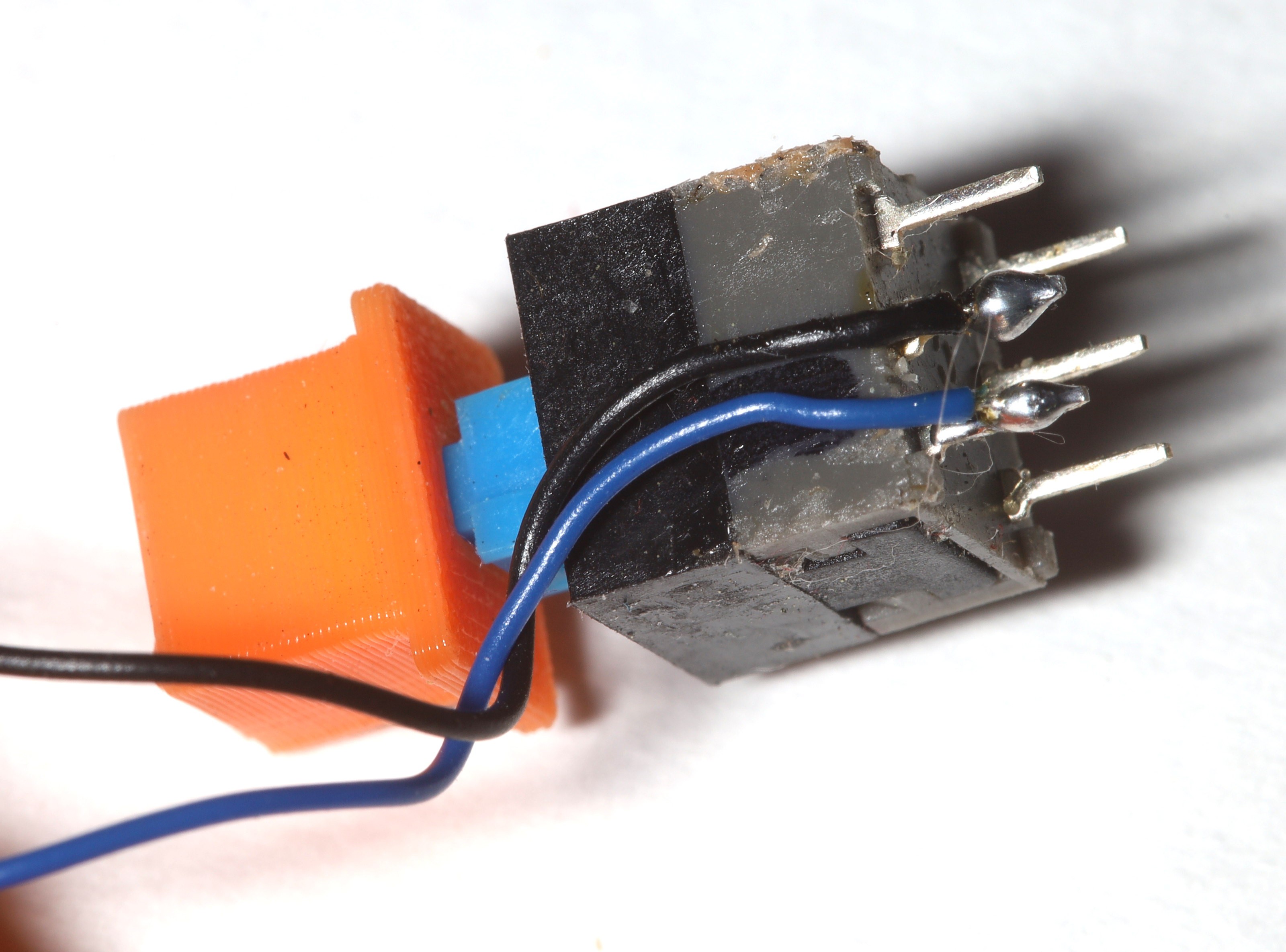
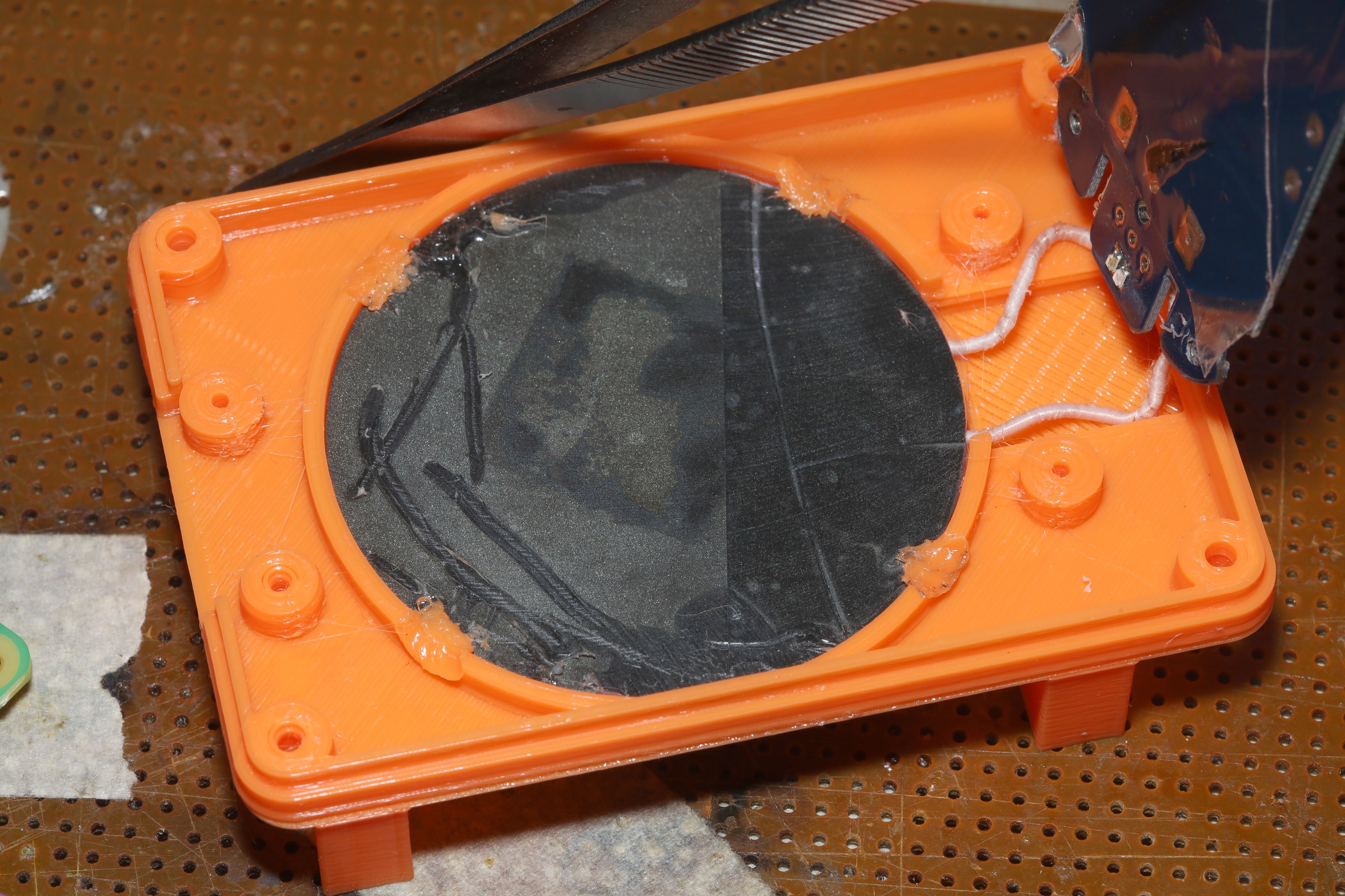
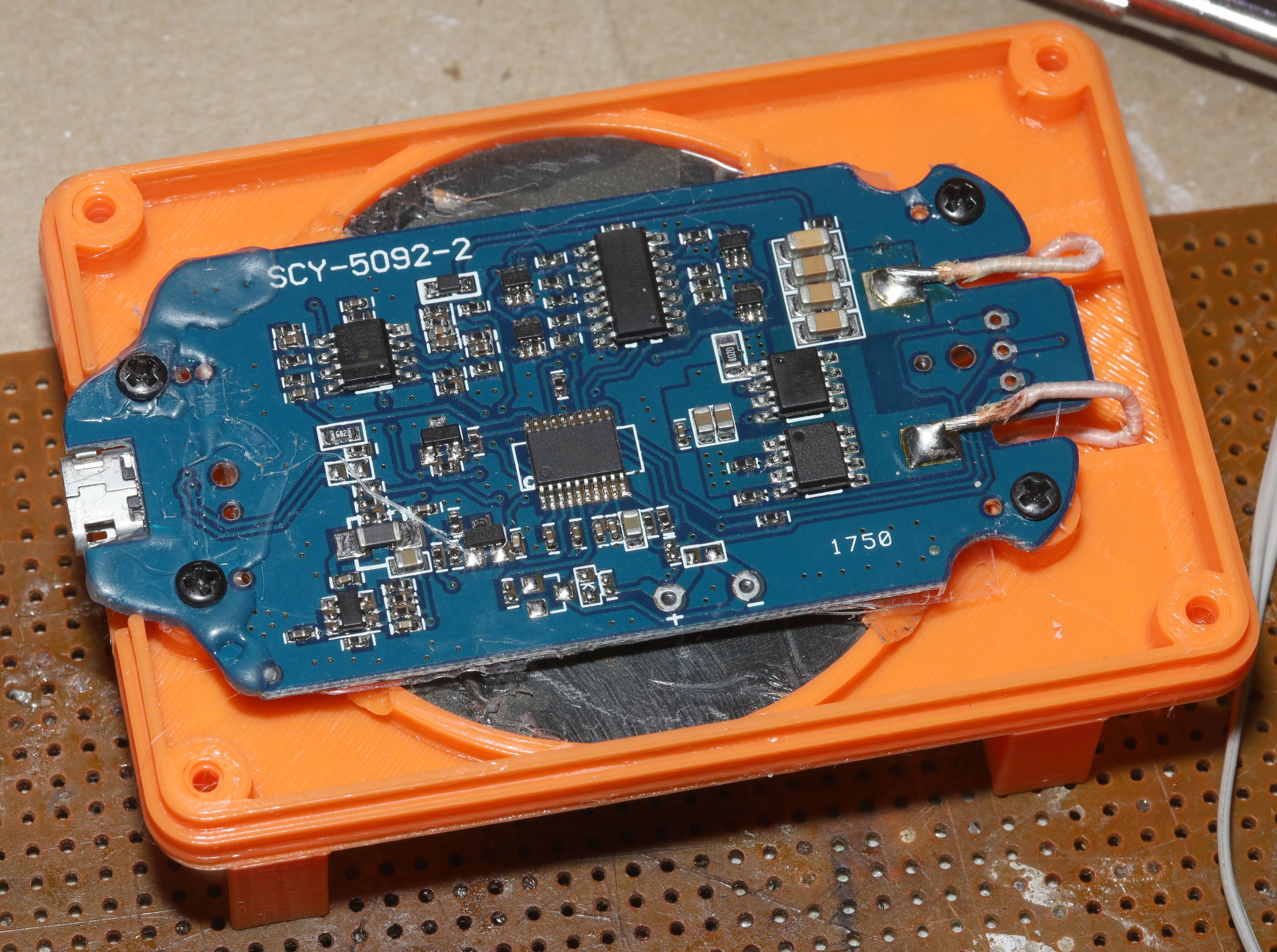
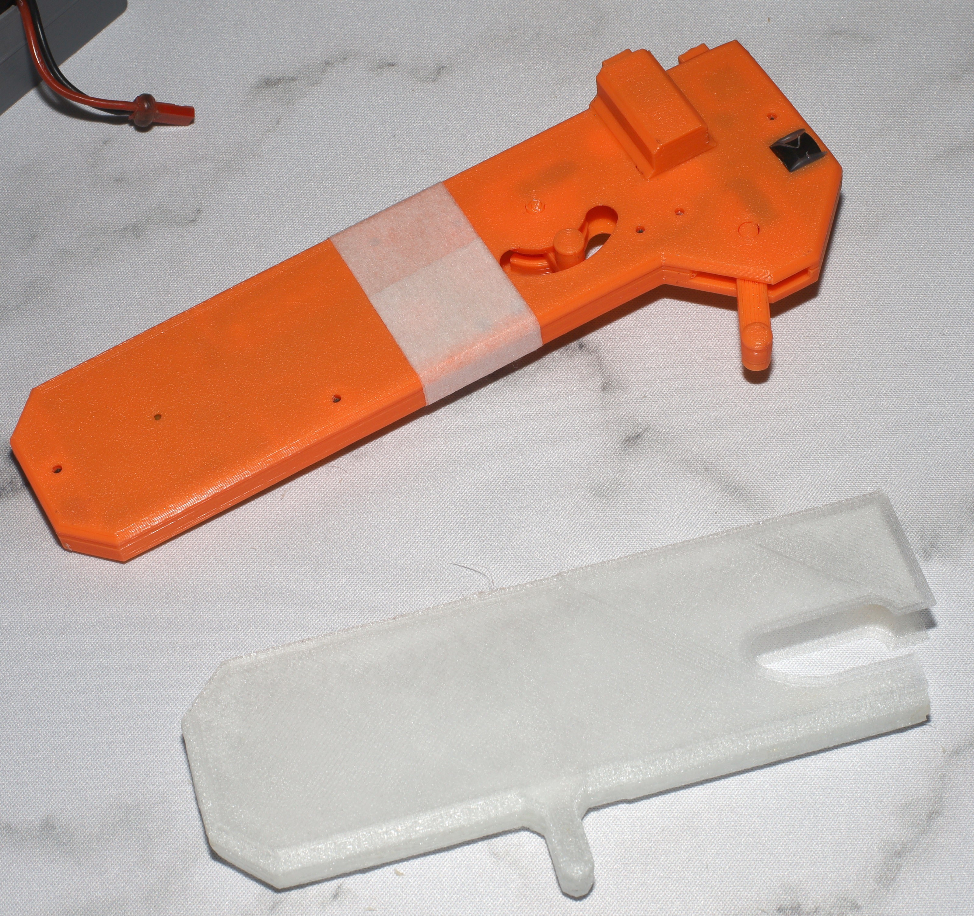
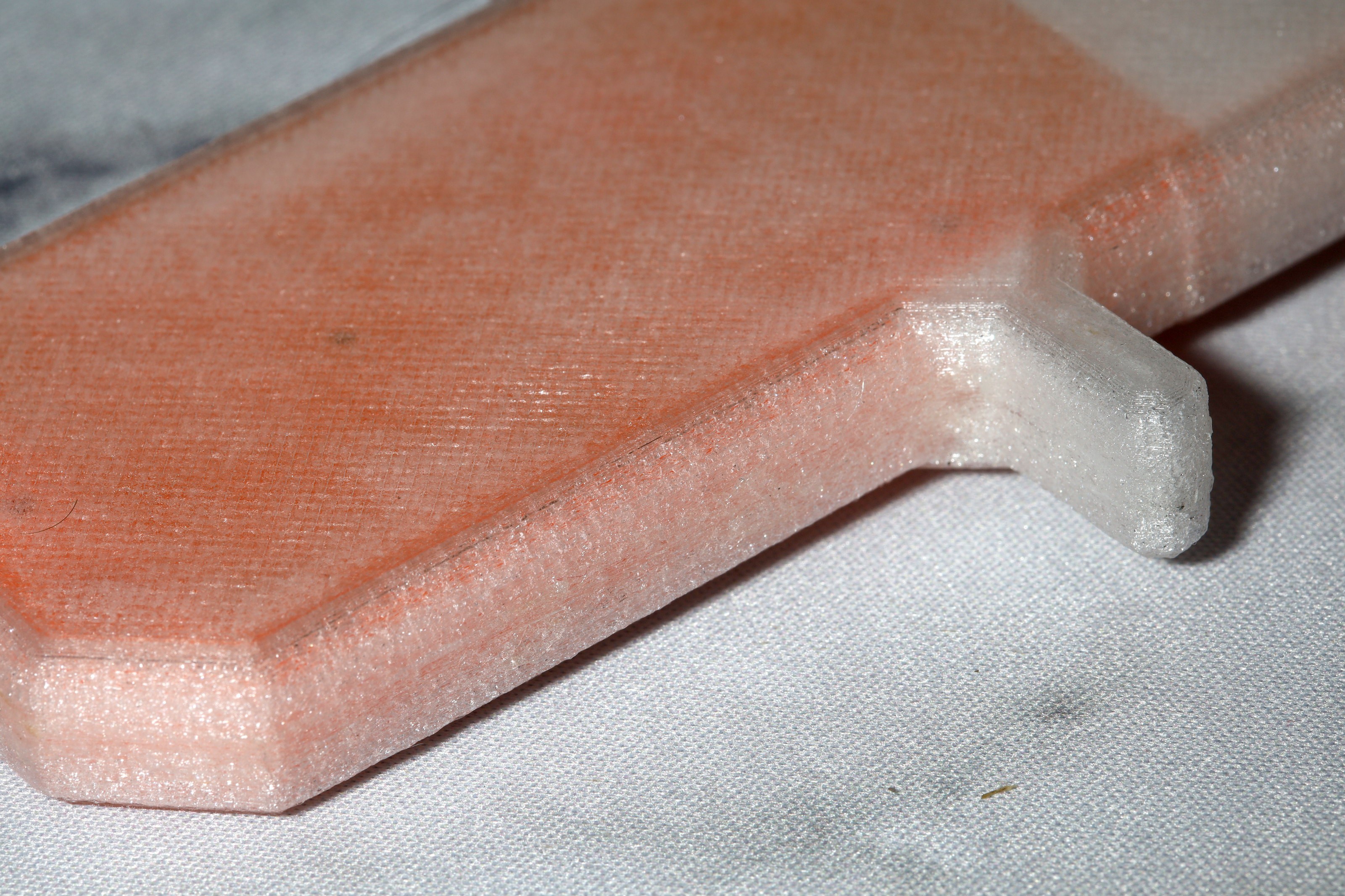
The final mechanical piece is the paw controller.  It uses springs from ball point pens.

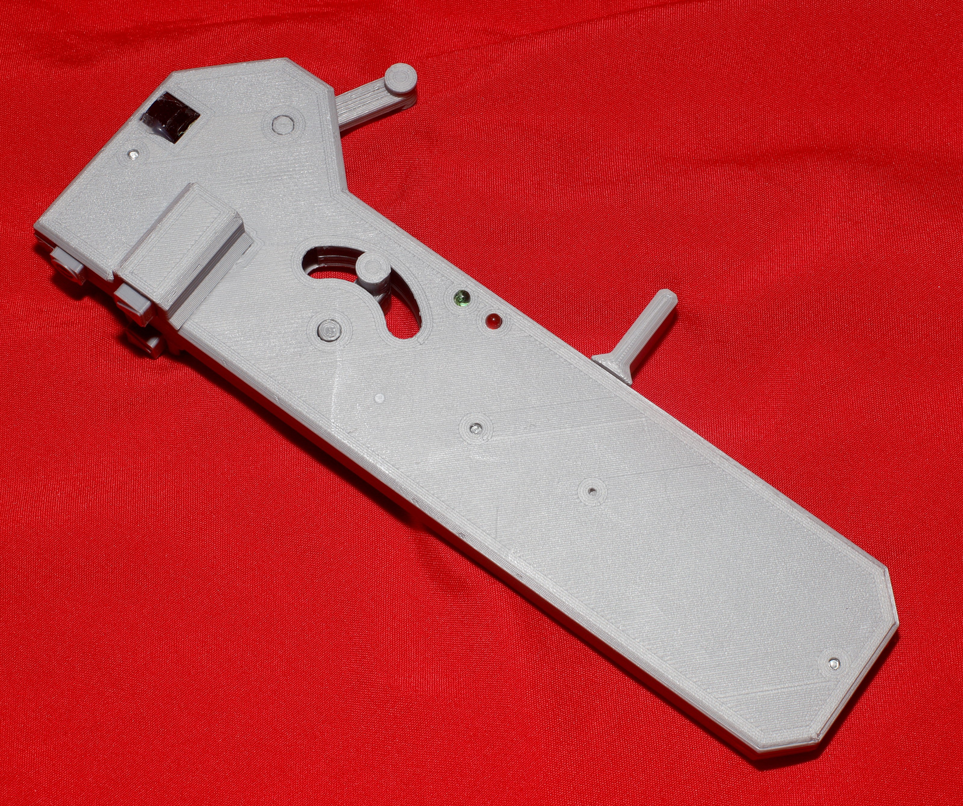
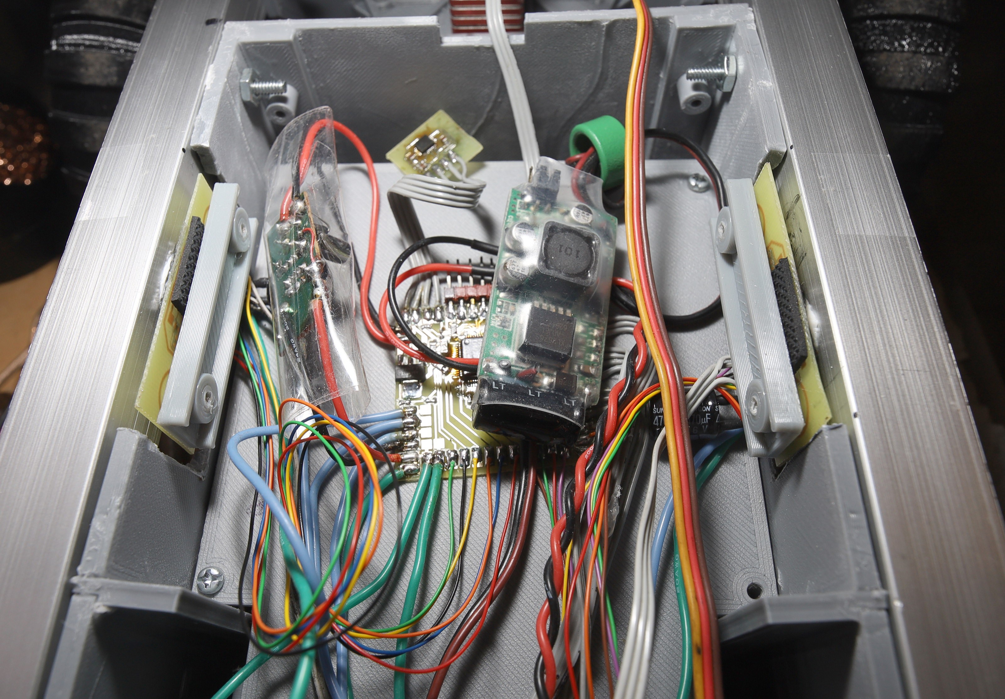
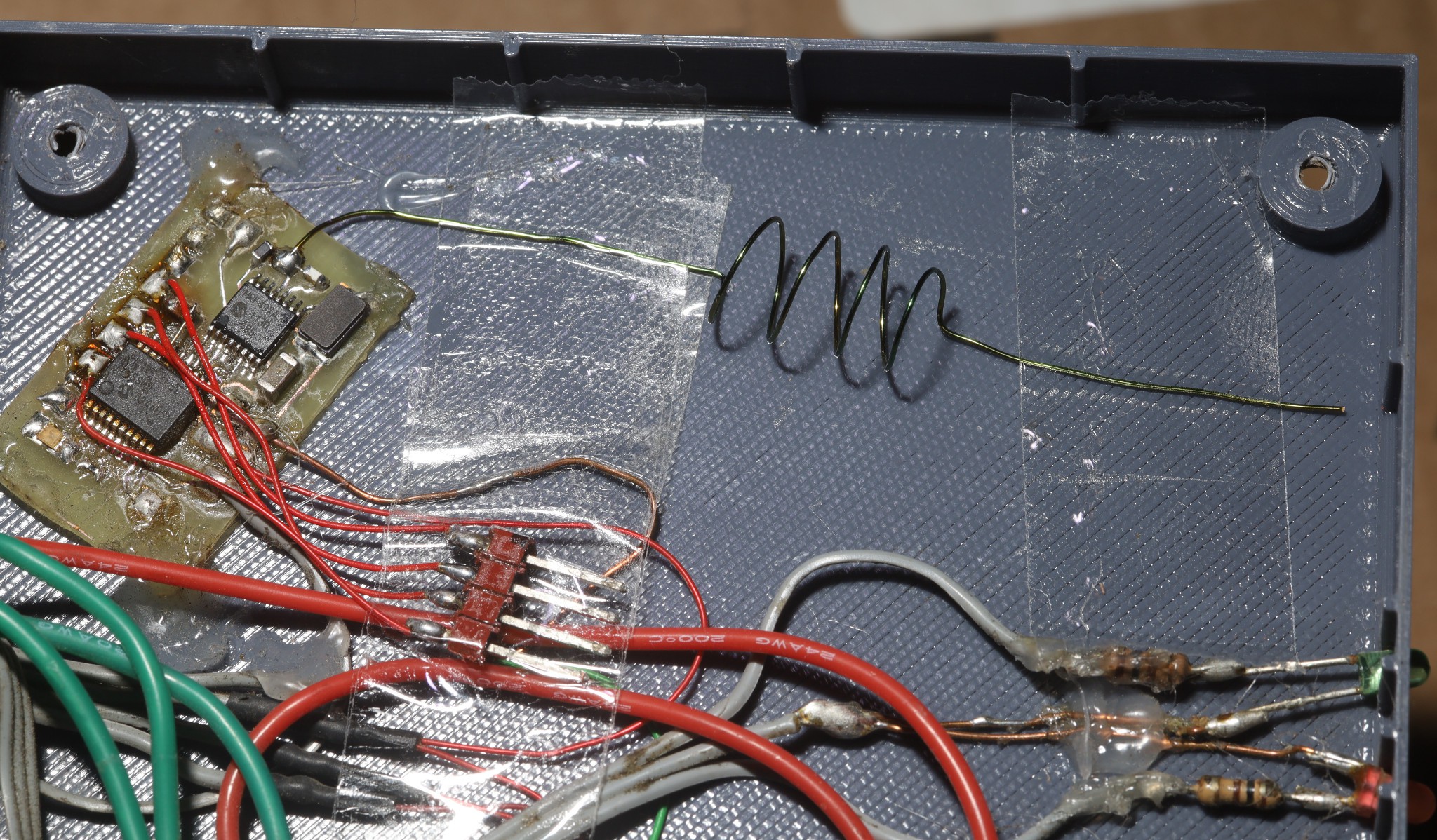
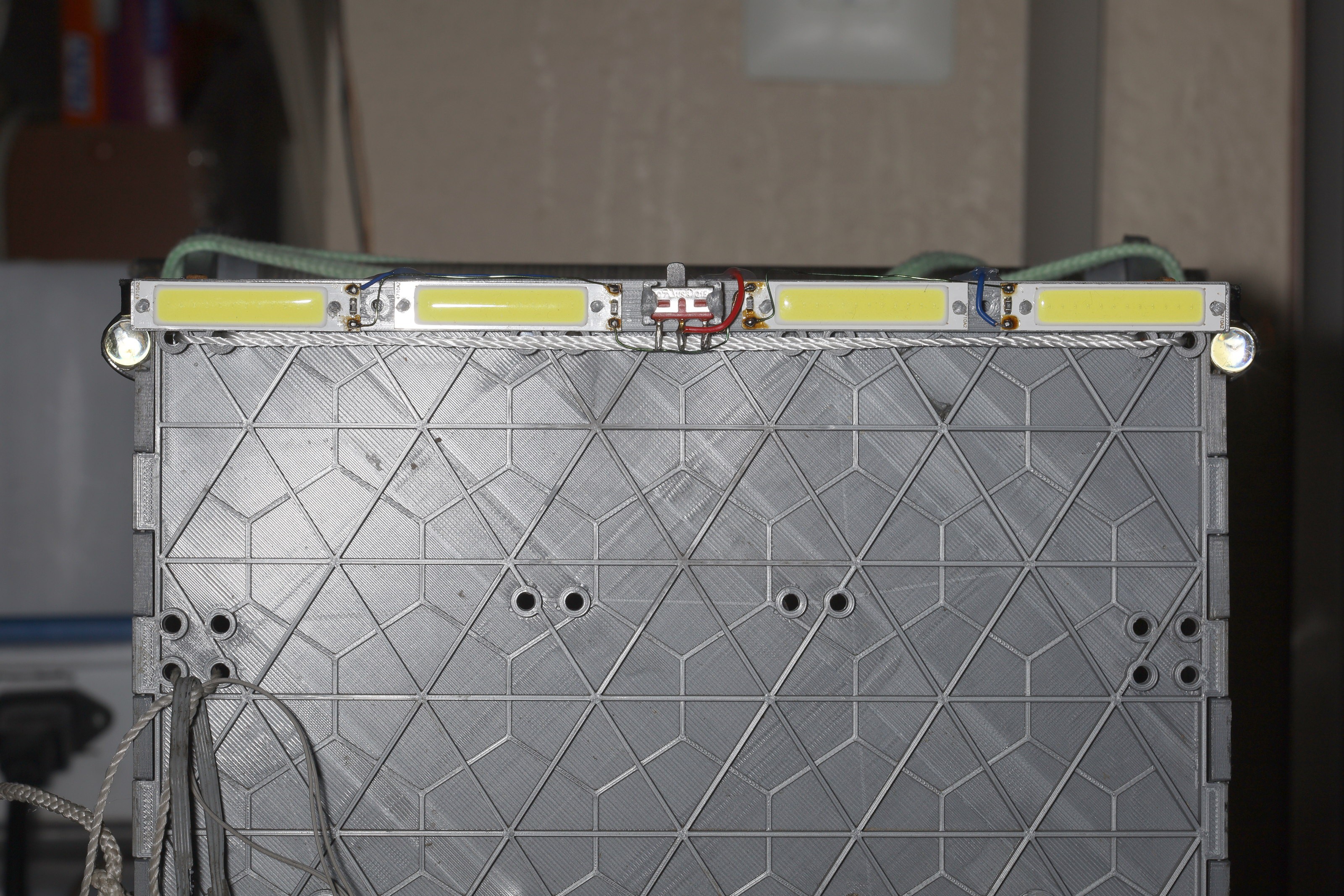
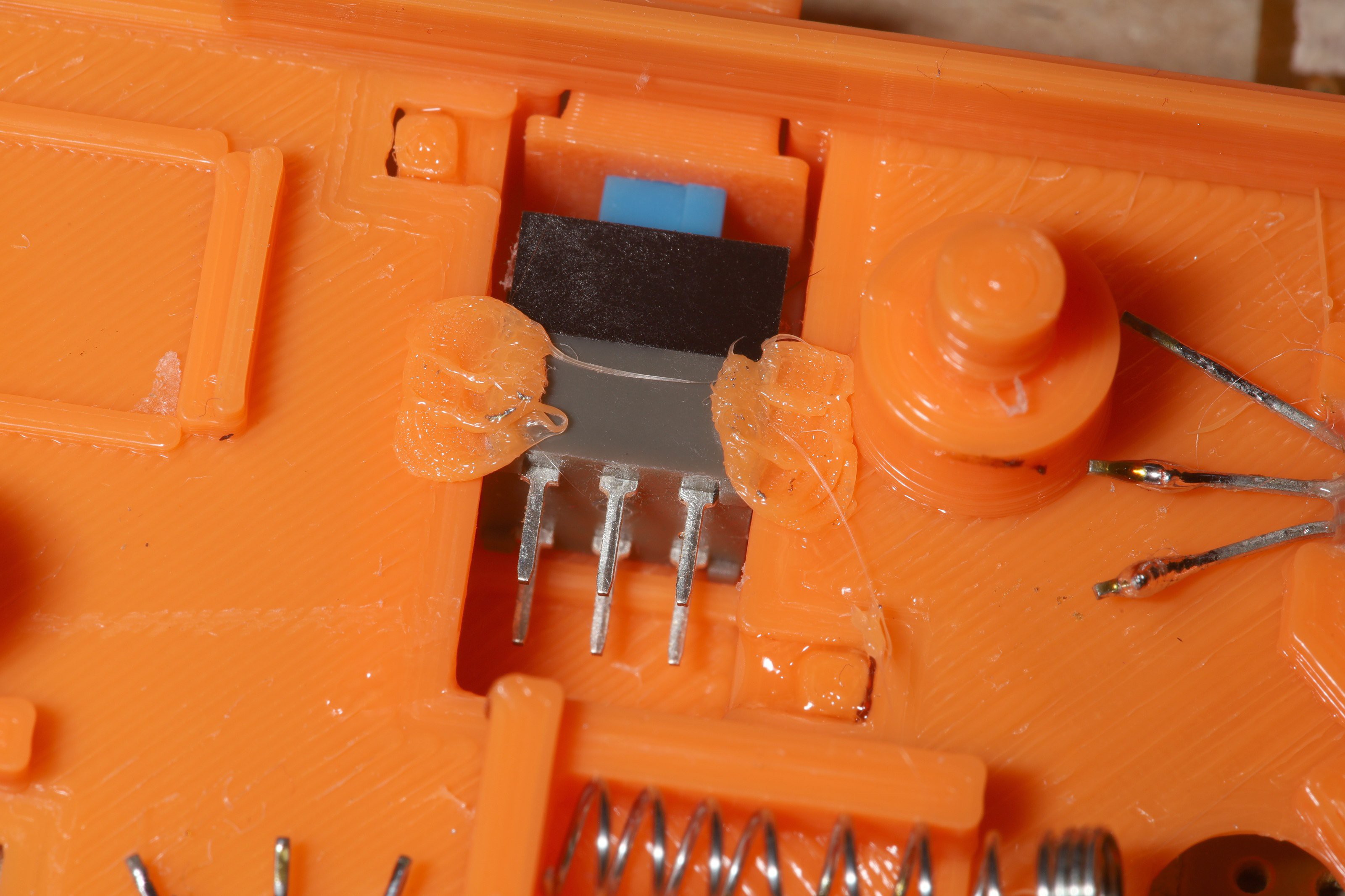
Electronicals provide semi autonomous throttle & steering.

  • Waterproofing ideas, 433 migration

    lion mclionhead02/04/2024 at 08:38 0 comments

    3 years on, it's become quite clear that the paw controller doesn't have to be ambidextrous.  It's a minor convenience in the scheme of things.  It manely has to be right pawed because lions eat with their left paw.  The convenience is enough to keep an ambidextrous variant around but a waterproof controller could come back into the picture if it was right paw only.  The current sock provides a lot more protection from rain than before, but a fully enclosed controller is needed for true running in rain.

    The steering could go back to 4 tact buttons.  Throttle could go to 2 buttons.  They could all be boundary switches to avoid the wear of tact buttons.  The motors & sensors are another problem.  The motor sensors would have to go in a potted enclosure.  Waterproofing gets expensive.

    ----------------------------------------------------------------------------------------------------

    Control over the years was done over 433Mhz 16mW CC1101, 2.4Ghz 60mW xbee, 915Mhz 100mW xbee, custom 915Mhz 100mW.  The 2.4Ghz was 1st to become unusable.  Then a drive through Manhattan showed 915Mhz was now completely unusable in that environment.  The decision was made to go back to 433Mhz with a custom 100mW transmitter based on the Si4463 for transmission & the ancient MRF49XA for reception.

    The mane challenge with this was getting decent range with antennas that fit in the limited space.  Got 1/4 wave antennas to fit with coils but it only went 20ft.  No radio ever got beyond 50ft because the truck is near the ground.  The leading culprit is the matching circuit.  Lions use very simple matching circuits.  The receiver just has a 47nH inductor between + & -.  The transmitter just has a 390nH inductor to Vdd.  The full matching circuits don't seem to offer any benefit besides suppressing harmonics.

    The Si4463 shows a receive sensitivity of -129dbm.  The CC1101 shows -116dbm.  The MRF49XA shows -110dbm.  It might be time to replace the receiver, but the Si4463 requires a lot more pins & is expensive.  The Si4463 can also change channels a lot faster than the older chips but...

    There haven't been any obvious benefits from frequency hopping.  It seems to hog more of the spectrum, if anything.  The kinds of conflicts encountered in the field are always usage of the entire spectrum rather than a single channel.  Lions have dreams of freeing up bandwidth by using minute long frequency hopping patterns over a very wide range but that would be a difficult problem.  Only 433-435 is legal.  Some frequencies would need frequent usage for synchronization packets.  The only benefit would be less detectable spectrum usage.

    Frequency hopping requires encoding the current channel in the packet to avoid crosstalk.  Finding enough bits usually entails encoding different fields using modulus operators instead of bitmasks.  A bitmask can encode 4 channel states & 17 speeds in 7 bits.  A modulus can encode 7 channel states & 17 speeds in 7 bits.

    Commercial 433 systems seem to be in the $150 range for 800mW. Nowhere near the required size, but they have full size antennas, proper matching circuits.

    https://www.foxtechfpv.com/rlink-433...xrx-combo.html

    There's a $25 chinese version if you have an aliexpress blessed credit card.

    https://www.aliexpress.us/item/2251801693568177.html

    The aftermarket RC parts business has otherwise all gone to DJI.

  • Translucent controller

    lion mclionhead07/03/2023 at 22:13 0 comments


    The current waterproofing & having all the LEDs on the inside worked, but growing pains with the orange beast finally reached a point where it was time. The mane problem was the power button constantly getting accidentally bumped when it was in leash mode. There were cosmetic desires for a glossy enclosure, better LED visibility.

    There was once a theory that an easily accessed power button would allow emergency killing of the motors. In reality, there was never a case where accessing the power button would have killed a runaway vehicle. The throttle stick always worked. If it got stuck, it was faster to unstick it than reach for the power button. The power button would not interrupt the leash & the leash now does half the driving. It was finally time to add some minimal guarding to the power button.

    Assembly still takes 2 days, manely involving fiddly bits, removing the old circuit intact, reaming holes. PLA rivets are much harder to undo than hot snot. Undoing them melts plastic parts & removes a layer from the inductor. It pays to make the PLA rivets smaller.

    The 1st sock rapidly turned yellow either from biological matter or sunlight. It definitely smelled like biological matter. There's a warping from the clamshell not fitting perfectly. Stick controllers still need lubrication. The hall effect sensors got moved to where the datasheet showed their hotspots + a .2mm margin & they reported nearly the exact center.

    Time will tell if a glossy exterior was a good idea. The sock might grip better with a buildtak finish.

    The next big feature is going to be OTA firmware updates. It's not possible to get the oral cues perfect as is. There should be a way to put the radio in a serial port passthrough by holding power & a direction button. Then it can run a bootloader. It's a big job.

    There's a growing desire to make the panels 1mm thick. They were made .8mm thick before lions were fully educated on PLA tolerances. There's a growing desire to make the power button exposed on 1 side & riveted in. The current hot snot system is a mess. Maybe it could be scotched over for waterproofing. Maybe it could be passively clamshelled in. The 3 button caps could actually be smaller. Still no better system than hot snotting the hall effect sensors.

    The mane problem with the translucent controller is it gets hot in sunlight & alignments change. 

  • Nose cone development

    lion mclionhead04/14/2023 at 23:39 0 comments

    As previously seen,

    https://hackaday.io/project/176214/log/212713-propdrive-dreams

     the cheapest way to get more speed was seen as creating a modular nose cone rather than expanding the motors, using hotter windings, or expanding the battery.  The nose cone had to be field removable without tools, stowable so the leash could be accessed, & not cover the headlights.

    The 1st step was converting the headlights to a narrow strip.

    Various nose concepts followed, with cardboard, coroplastic, & PLA.  After many miles, the best performing one was 3 sided with permanent string holding the bottom & a removable string farstening the top to the truck.

    Ideal speeds with a nose cone:

    #    dist    sec    min/mile
    1    213    43    5:42
    2    201    44    5:45
    3    203    44    5:44
    4    208    46    5:49
    5    201    46    6:3
    6    211    44    5:51
    7    205    46    5:52
    8    208    44    5:53
    9    206    47    6:0
    10    204    45    5:43
    11    211    43    5:42
    12    200    44    5:47
    13    203    46    5:58
    14    306    70    6:6

    Typical speeds without a nose cone:

    #    dist    sec    min/mile
    1    208    48    6:9
    2    305    73    6:24
    3    405    98    6:28
    4    408    103    6:43
    5    404    100    6:35
    6    404    100    6:34
    8    400    101    6:45
    9    407    110    7:14


    Speeds with a nose cone were highly variable, depending on weather, payload, wheel alignment.  Without a nose cone, it was guaranteed to have a hard time getting above 6:30/mile.  With a nose cone, there was a possibility of it getting above 6:00/mile.

    There's no correlation with the number of sides of the nose cone.  A 2nd nose cone on the back might buy it more speed.

    The latest nose cone is glossy & collapsible.  It rests on the bumpers while clearing the leash.

  • Charging stand upgrades

    lion mclionhead01/21/2023 at 23:06 0 comments

    To make the controller waterproof, the TPU sock eventually had to be permanent which meant updating the charging stand.

    In this process, the charging inductor cracked.  Those are really fragile.  If the enclosure is too small or you try pulling it out when any PLA rivets are holding it in, it's going to crack.

    The temptation is to press it when grabbing the charger. The problem is the new design fully exposes the inductor & nothing supports it in the middle. Below it is an air gap followed by the circuit board. At least Walmart has qi chargers locally at a reasonable price. The easiest solution is to not PLA rivet it & have some kind of foam press it out from the circuit board. It has a packing tape cover which could also prevent it from rotating.


    The lion kingdom's PLA riveting skills have improved to melting it with a brushing motion of the soldering iron rather than keeping the soldering iron stationary. This keeps it from sticking to the soldering iron. Then use the mark 1 lion paw to press it in position before it cools.

    With the sock now permanent, it would have to be translucent to see the charging LED.

    Translucent TPU & PLA entered the printer.  The decision was made to retire orange PLA & hard black TPU.   TPU is manely used for tires.  The hard variant had very little use.

    Panels which dominate lion prints come out a lot clearer than walls.  It not obvious whether the filament came wet from China.

    The charging LED is now visible.  

  • New remote

    lion mclionhead01/10/2023 at 07:30 0 comments

    The mane desires in a new remote were improved water resistance & replacing all the hot snot with PLA welding.

    PLA welding was a successful failure.  1 switch still ended up needing hot snot.  The best way to install the hall effect sensors was still to put a dab of hot snot down 1st, then press the hall effect sensor on, then flatten the dab. A dab of grease on the hall effect sensors still made a big improvement. Grease should not go anywhere else as it causes sticking.  The only reason the joysticks get stuck is friction with the hot snot & grease.


    A new trick with PLA welding was to melt the PLA with the iron but use the mark 1 lion paw to press it down. It adheres to the iron but not to the lion paw.

    In the interest of water resistance, a sock covers the entire handle.  The sock is removed for charging.  If there's any evidence of how bad lions are at 3D concepts, it took a long time to realize the finger grip could be part of the sock. It actually holds water but doesn't have enough friction to stay on. 

    The mane problem is the welds don't go as deep as hoped. No point in using orange PLA if the sock is covering it. Low cost TPU is quite good for covers like this. Trying to stretch it over the steering stick was hopeless, so it got a cutout.

    The leading idea to get it to stay on is taping the PLA to make it thicker.  Other ideas are to print ridges inside the sock or make the sock narrower at a point.  The problem with making the sock expand around the enclosure is welding the sock requires fitting it around the enclosure 1st.  It would need a blank smaller than the enclosure just for welding.


    Power consumption was 50mA, so a 260mAh battery is only going to last 4 hours on a good day. It needs the 400mAh battery which somehow fit in the last one. The 260mAh required a lot of coaxing to fit in there. If the radio constantly transmits, it burns 120mA. The transmit duty cycle is 5ms on & 35ms off. The PIC has to run at full speed for the sounds.

    There's 1 heroic bodge wire to connect MISO to the radio. Despite every effort, the radio failed to initialize without several power cycles. The datasheet says Vdd needs 1ms ramp time. The LP2989 has a 5ms ramp when probed.

    Merely cleaning the flux got it to start despite the LP2989 issue. Getting rid of 100uF of capacitance didn't do anything.

    After fighting to get the sock over the LEDs, it was decided to put the LEDs inside the case & hot snot the LED holes shut. With orange PLA, the red charging LED shows nicely but the green transmitting LED is barely visible. Transparent PLA would be ideal, but there's a real need for white PLA for an LED diffuser. Nylon paper might work as an LED diffuser, which would make transparent PLA the better deal for fabrication.  LEDs that diffuse through the enclosure should be a bigger part of all designs.

    The hall effect sensors are 1.3mV/G so they never saturate.  There is a desire to make the handle narrower to compensate for the sock size.  The steering lever should be either square or longer to compensate for the sock.

  • Secrets of the Si4463

    lion mclionhead01/09/2023 at 19:38 0 comments

    It was finally time to build a new remote control for better water resistance.  Sadly, the original Si4421 radios were discontinued & problems with the RFX1010 burned the last 2 of those chips.  It was never figured out why those failed after working in 2 boards.  The Si4463 promised to make enough power to not need a front end & has a higher bandwidth.

    The Si4463 is 10 years old but already a beast.  It requires all 4 SPI pins.  It uses the MISO pin for flow control. While the datasheets show the pinout & an example schematic, they don't have any inductor values. 

    The new dance is separate RX & TX antenna pins.  For transmitting, a simple 100nH seemed to do the job.  There's no plan to use it for receiving.

     The register descriptions in the datasheets seem to be obsolete.  All the register values are documented by the Wireless Development Suite (WDS3).  Bringing it up is not possible from the datasheets.  The WDS3 has a radio configuration application which generates all the required code.  

    You have to export a custom project after setting all the configuration bits.  The header file option doesn't work.  The 2 key files it generates are

    src/drivers/radio/Si446x/si446x_patch.h 

    src/application/radio_config.h

    The key object is the RADIO_CONFIGURATION_DATA_ARRAY.  It's just an array of packets to send to MOSI with flow control codes.  The 1st byte is a packet size.  Then you send the packet.  Then you poll the CTS register before reading the next packet. 

    SPI is MSB 1st.  The datasheet didn't say that.  The flow control procedure is in the radio_comm_SendCmdGetResp function.  Part of the auto generated array is a firmware patch which requires 512 bytes.

    The only requirement for using a UART to modulate the signal is declaring 1 of the GPIOs as an input & selecting Direct TX as the project.  Set the other GPIOS to TRISTATE & they can be connected to ground.  Then send a START_TX with 0 for all the arguments.  That is auto generated in the si446x_start_tx function.

    The other trick is setting the deviation to match the Si4421.  That's how far the carrier shifts above & below the center frequency for modulation.

    For frequency hopping, the channel is sent in the START_TX command, but this is only accurate to 30Hz.  The base frequency is accurate to 1Hz.  The base frequency is set by the RF_FREQ_CONTROL_INTE_8 & RF_MODEM_AFC_LIMITER_1_3 registers.  The channel spacing on the Si4463 is only accurate to 30Hz  while on the Si4421 it was within 10hz.  To save power, use the channel number in the START_TX command.

    The PA power level is 0x7f for full power & 0 for lowest power.

    There is a desire to resend the packet multiple times per hop, but this requires a receiver change.  Without a unique ID in each resend, it seems to screw up the hop timing.

    The ramp up time for transmitting is under 1ms on the Si4463, which greatly reduces the amount of current required from the 5ms required by the Si4421.  


    Going into standby mode

    The mane thing is all the GPIOs have to be configured as TRISTATE or INPUT.  If it's driving the GPIOs, it sucks 10mA in standby mode.  Then you're going to put it into standby mode when not transmitting.  Poll CTS 1st, then issue the CHANGE_STATE command for standby/sleep mode.  Polling CTS after the command might wake it back up.  This drops the current to 0 when not transmitting.

    Of course, the typical usage involves long delays between state changes, so you shouldn't need to poll CTS at all.

    Startup difficulties

    The mane reason it won't start up is the ramp time for Vdd being too high.  The easiest solution is to connect SDN & drive it high until Vdd is done.  Thus, it takes 5 digital signals to start up.

  • Dead motor #2

    lion mclionhead11/23/2022 at 00:07 0 comments

    3 months after the left motor winding died, the right motor winding died.  This one died in the dead of winter no less & smelled like burned enamel.  It was last rewound on April 29 so it only lasted 7 months.

    Left Motor windings:
    Nov 27, 2021: 20 turns 26AWG
    Sep 24, 2022: 20 turns 26AWG

     Right Motor windings:
    Apr 26, 2022: 20 turns 26AWG
    Nov 22, 2022: 20 turns 26AWG

    The left windings lasted a solid 10 months.  The right windings were staggered.   They're rated for 150C & they're confirmed to melt at 300C.  Lower temperatures allow longer duty cycles, but all temperatures eventually melt.

    Suspect running faster more often is burning them out.  At this point in the history of motor rewinding, nothing new could be added.  The question is when is rewinding motors going to take more time than designing a temperature sensor.  

    The leading ideas are thermisters & thermopiles.  Temperature sensors are not standard in electric bike motors, despite Louis Rossmann's vlogs.  

    Guys just epoxy them to the motor windings.

    This one is siliconed to a motor case.

    The leading idea is cutting down the heat sinks since they're not doing anything, permanently farstening thermisters to the heat sinks next to the motors.  The heat sinks did a good job tracking motor temperature, but didn't remove any heat.

  • Unitree robot

    lion mclionhead11/11/2022 at 02:20 0 comments

    China made a bit more progress towards the ultimate goal with another robot dog.  

    https://www.unitree.com/en/go1

    This one is specifically marketed as a running coach & food transporter.   At the $2700 price point, payload is 7 lbs freedom units.  Maximum speed is 5.5mph freedom units.  Prices beyond $3500 enable speeds over 8mph.  Range is 1 hour.  It tips the scales at 26lbs freedom units.  Of course, the reviewer didn't test any of the parameters.

    It uses direct drive brushless motors.  There's no mention of walking on unimproved terrain, navigating obstacles, navigating crowds of animals.  It has a bulky 2 paw controller & relies on a brain to navigate.  It has some ability to stay in a fixed position relative to the user, through machine vision, but also shown is a GPS tag as a backup.  They emphasize the SLAM functionality.  


    There's a 3-6 month warranty, depending on the component.  The lion robots need major servicing by 6 months or 1000 miles.

    Lions aren't sure they'd want to haul 26lbs of robot around if it died, but there's definitely a lot to be gained by making it heavier.  The lion robot is sized for its typical role.  The typical need is a maximum speed of 10mph, payload of 5lbs, range of 4 hours, light enough to carry 6 miles if it dies, manual driving.  

    We're not sure why everyone in the video is sitting in an office to stare at confuser screens.  It seems everyone in the transportation business is required to go to an office.

    Bosstown dynamics always claimed the high mass & pinch points were the reason for its dogs not being intended for consumer roles.  In typical chinese style, the users are expected to take risks.

  • Rudolf update

    lion mclionhead10/23/2022 at 03:16 0 comments

    Installing roborudolf is the 21st century equivalent of decorating the tree.

    There is a desire to repaint the antlers with metallic brown, but this would entail rebuilding all the LED strings.   Reprinting the antlers would fix some fitment problems.  Another desire was flattening the tips of the antlers.

    The headlight becomes another difficulty when the nose is installed.  The red LEDs might be enough to replace it, if driven at their maximum voltage.  The plastic dome could be taken off.  The headlight could be installed above or below the nose.  Maxing out the nose would entail yet another voltage converter.

    Metallic brown is definitely more fitting for a robot.  It went on more even than flat brown.  Printing .8mm nozzle .32mm layers took up more ink.  The ideal antler is metallic brown TPU, but that would be much harder to bond.  These were printed as solid halves with 20% infill.  The easiest way to bond was gluing a right angle out of 1 half & the base, then gluing the remaneing half.

    New antlers fitted with lights.  The metallic brown is less obvious in the dark.  

    Locked & loaded

  • Propdrive dreams

    lion mclionhead10/22/2022 at 20:12 0 comments

    #    dist    sec    min/mile
    1    205    45    5:49
    2    209    46    5:47
    3    200    46    5:59
    4    203    46    5:58
    5    201    48    6:22
    6    200    47    6:12
    7    311    71    6:19
    8    312    70    6:11
    9    304    75    6:34
    10    303    76    6:42
    11    401    98    6:29
    12    403    97    6:24

    The lion kingdom evolved a routine of increasing interval distances as the headwind slowed it down.  In this case, the headwind was weaker than expected & the 400's ended up faster than the 300's.  There's not enough power to hit 6 minutes in the headwind as previous robots did.  

    The propdrive 5050 is believed to have the key to 6 minute pace intervals.  The weight increase could be manageable.  It would fit in the latest wheel design.  It only wouldn't fit in previous wheel designs which directly copied the dimensions of the lunchbox.

    A pair was once $90 & after bideflation, was $120.  The lion kingdom worked out a way to pay so much money when larger motors in the form of a hoverboard would be cheaper.  It's all about saying the premium is for miniaturization.

    There's still the idea of having large diameter motors on the outside, extending the container all the way to the bottom, & making the container narrower.  The electronicals & batteries could go inside the motors.  This idea could also involve extensions of the container inside the motors.

    The most radical idea is having a single traction motor which wraps around the entire container.  It would require a tank tread to achieve the various bends.  The motor is shaped like an oval.  The problem is carrying the vehicle by the tire, mounting the camera on it, storing things which are taller than the motor.  It's not believed having a single motor passing down the middle of the container would be practical.

    The trend is large, hollow motors with the container integrated in the empty parts of the motors.  It's believed these motors can be constructed out of electromagnets bolted onto a linear PETG framework & permanent magnets embedded into TPU.  Smooth sliding of the TPU over the PETG would take some creative bearings & seals.  Chinese do sell bare ball bearings without the races.

    A gearbox or belt is just a way to increase the diameter of a motor, but compress it into a smaller area & make a lot of noise.

    The leading candidate for increasing the speed is an aerodynamic nose cone.  The problem with a nose cone is it's going to cover the headlights.  It could be translucent PLA.  The headlight could attach to the front of the nose cone & the front could be on top.  The nose cone has to fold up & fit in the container.  It might work if it hangs from the top.  

View all 49 project logs

Enjoy this project?

Share

Discussions

James Rowlands wrote 09/14/2022 at 09:14 point

Hey! This looks like a neat project, as well as your running aid. Does that auto-follow? If so, how did you implement that?

I plan to one day produce a 'cycling aid', along the same lines, with enough of a payload (>20kg) to be useful on grocery runs. Do you think your printed truck would be a suitable RC vehicle for this? Or perhaps a starting point? I'd be after a vehicle that can keep up with, brake faster than, and handle the kind of terrain a bicycle can.

  Are you sure? yes | no

lion mclionhead wrote 10/23/2022 at 03:12 point

Definitely need hover board motors for 20kg.

  Are you sure? yes | no

Similar Projects

Does this project spark your interest?

Become a member to follow this project and never miss any updates