 kelvinA
Media
Inspiration and/or examples of working principle
I found this video which shows how the slider would ideally perform, just that you can press down on it and it can be set to allow movement "infinitely" in either direction.
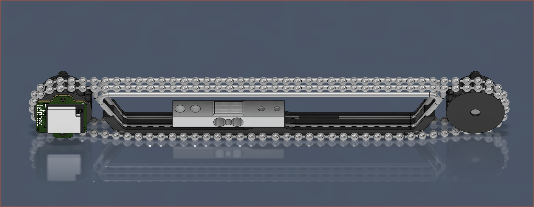
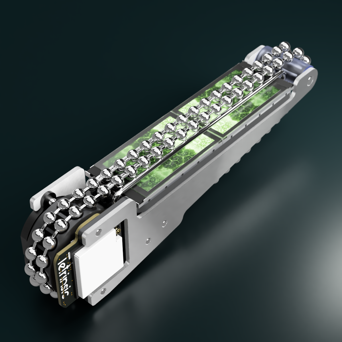
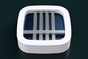
Tetrinsic is the merge of the above motorized sliding potentiometer and the SmartKnob View:
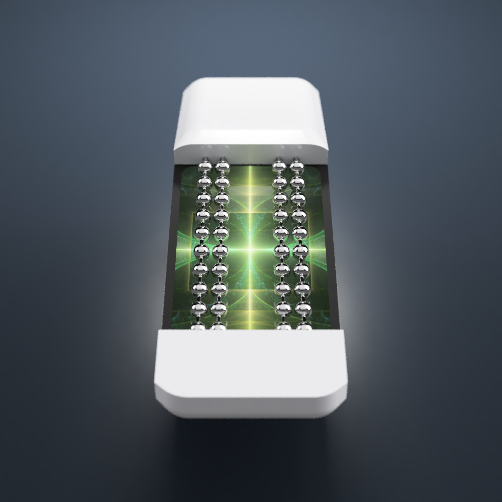
The visible area is designed to be as minimalist as possible, so that things like an LCD backlight can be used for designs:
The cool thing about Tetrinsic is that you don't have to remove a magnetic top layer (as seen in Flux) or hotswap out the switches (on a more traditional keyboard) if you want to change tactility. Just tune it to your precise tastes in software.
Navigation
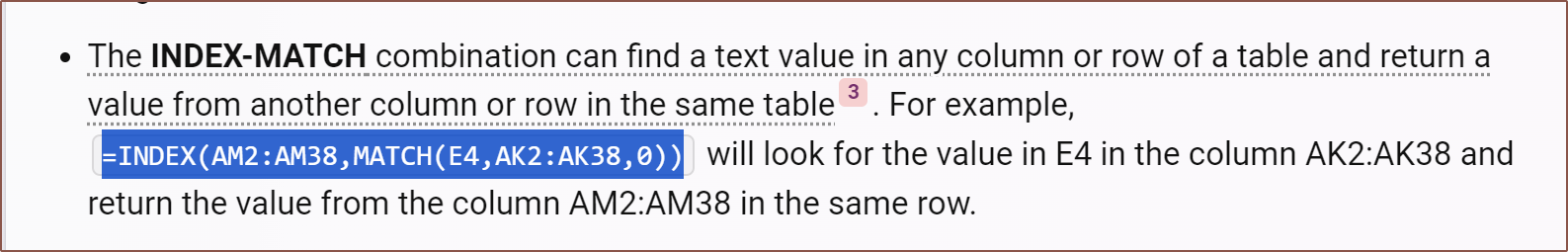
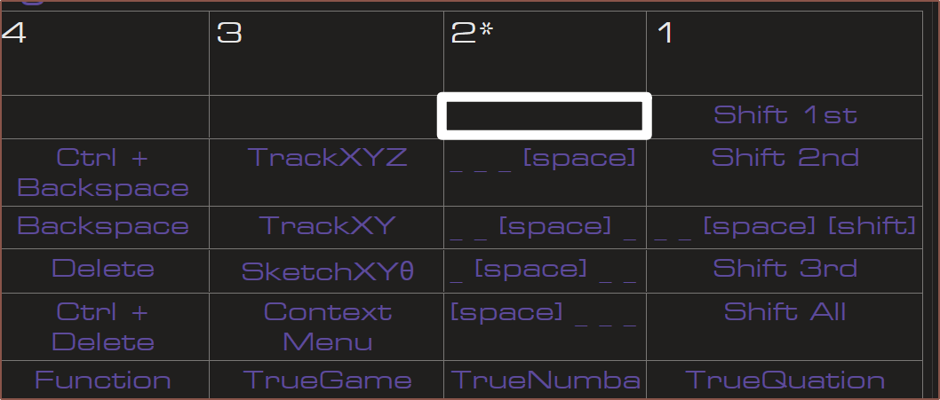
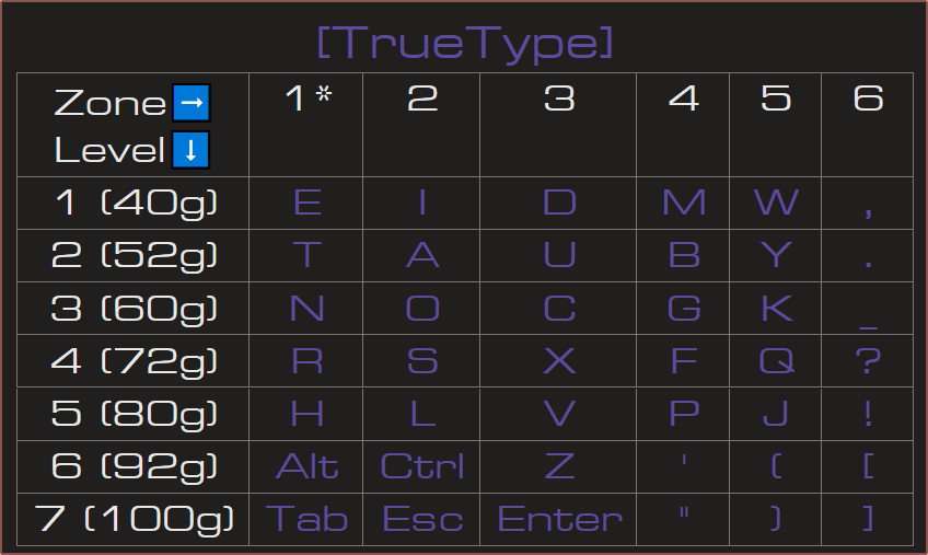
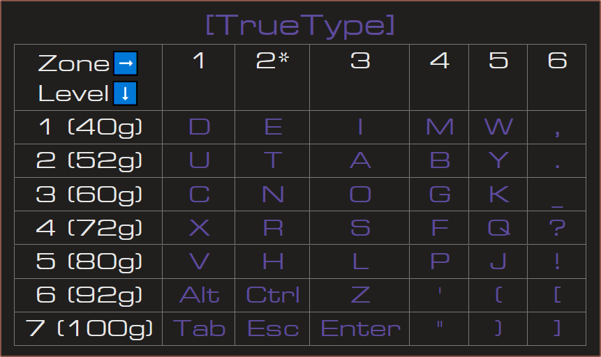
The title tag system is explained here, and the table is updated when a change occurs. Notable logs have bold L# text.
Read more »

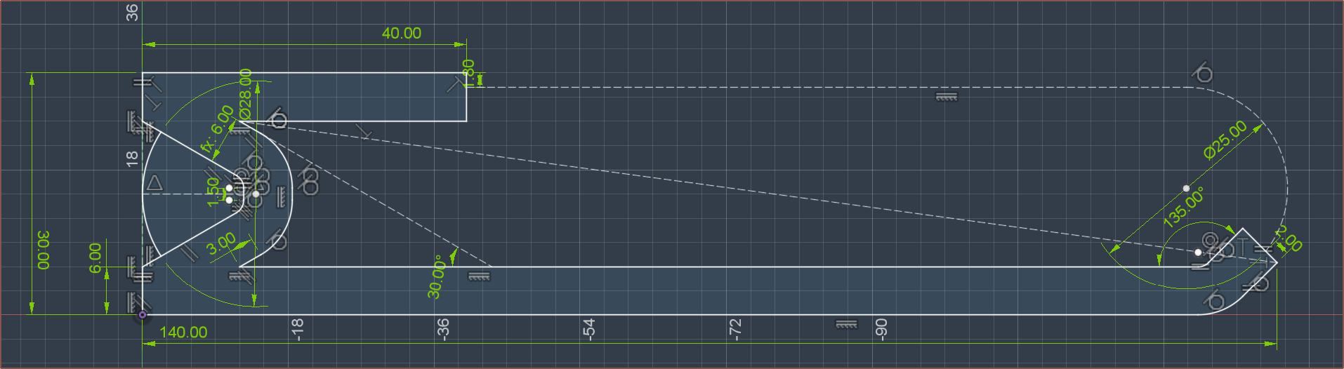
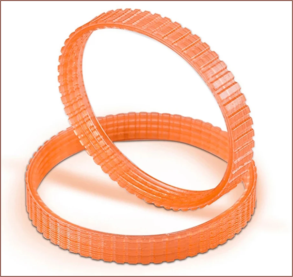
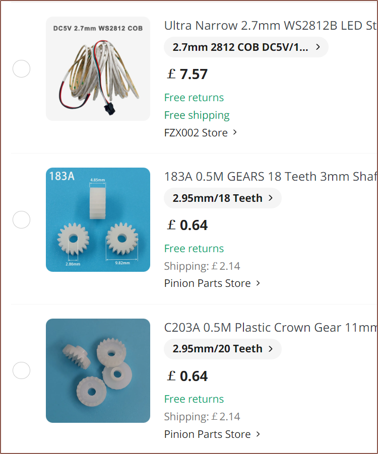
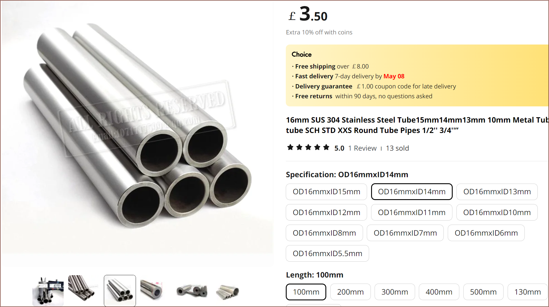
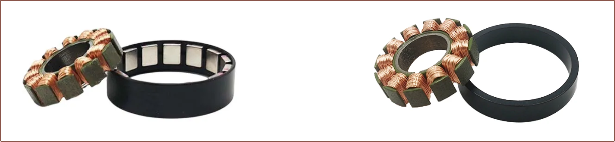
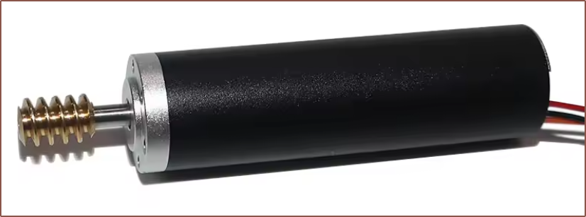
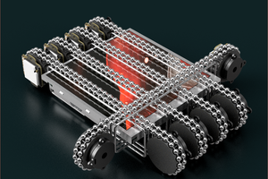
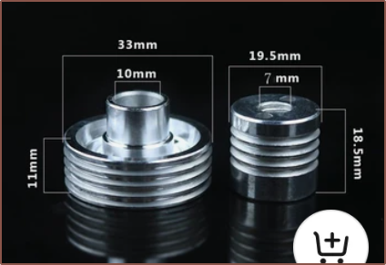 It also seems self-centering, meaning that I wouldn't need the flange and so I could probably tweak the gears to use something like this:
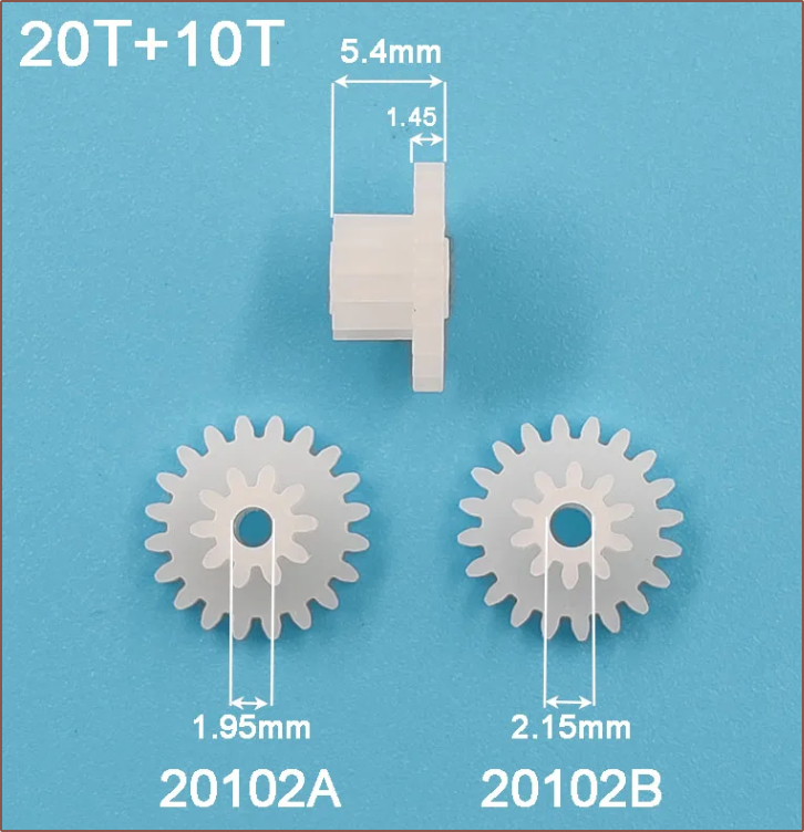
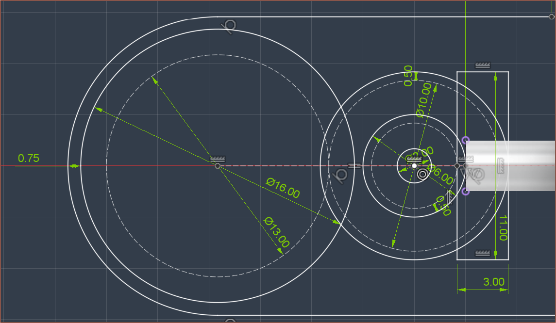
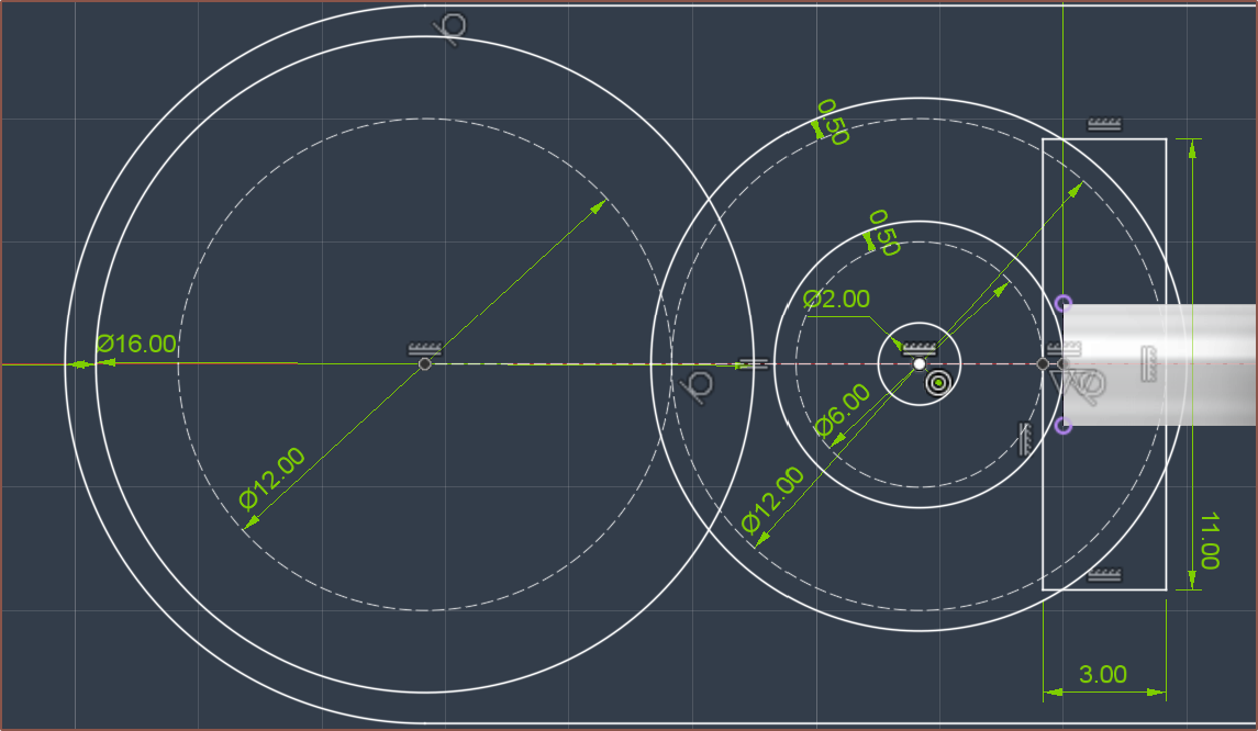
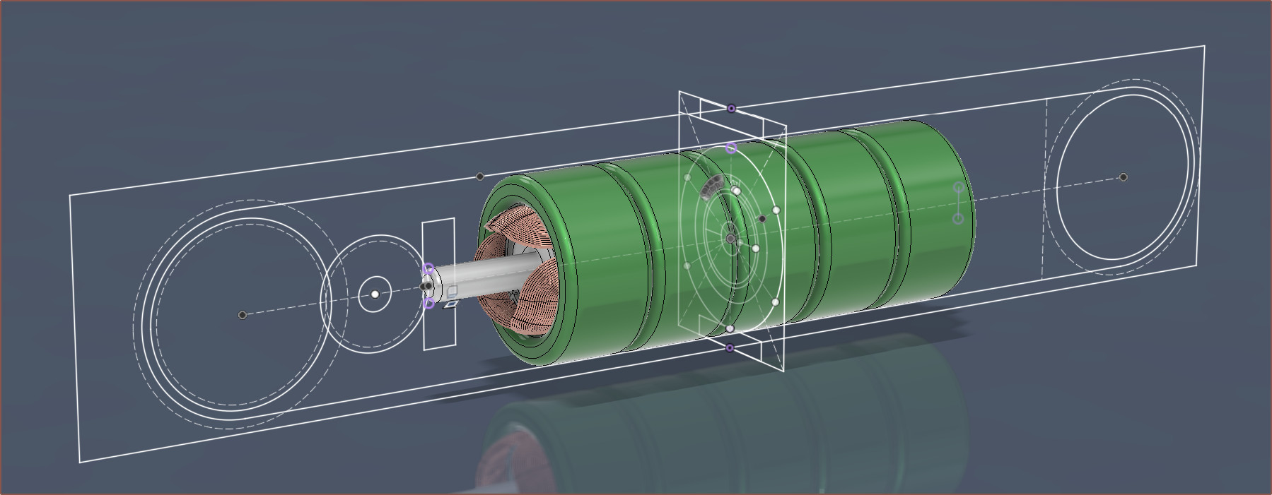
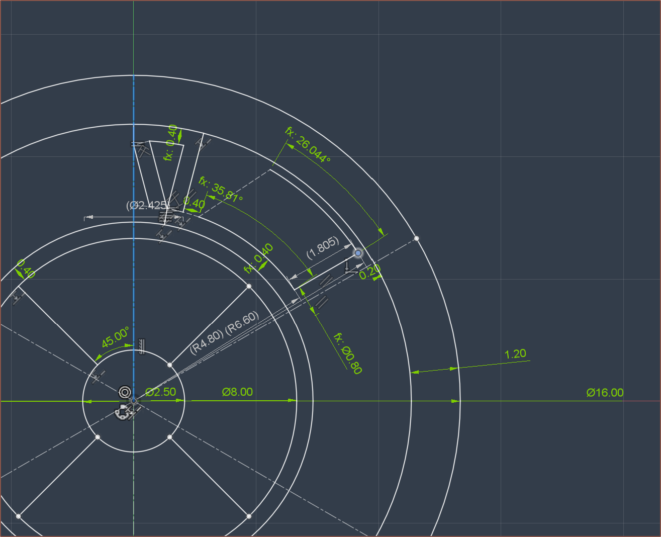
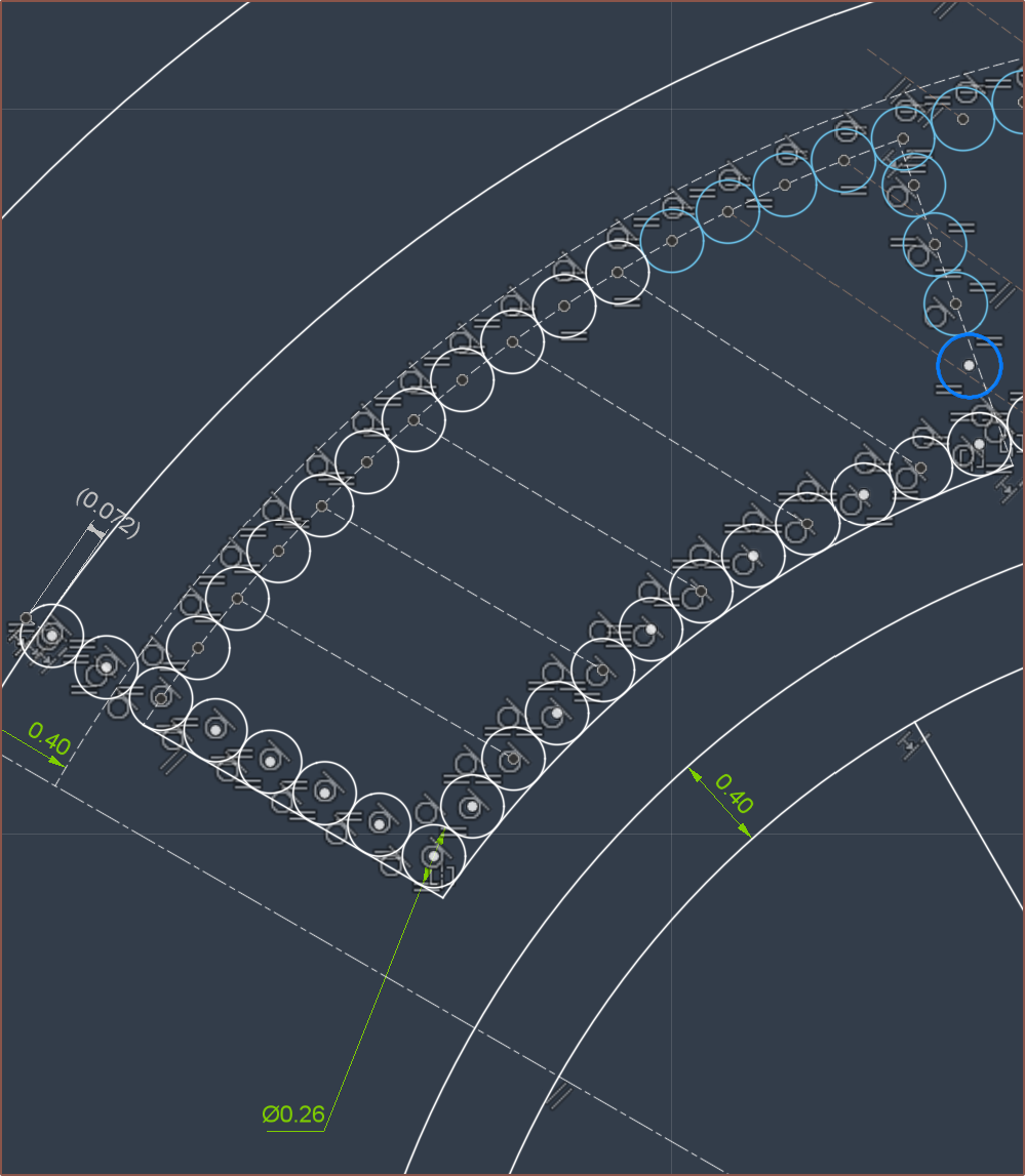
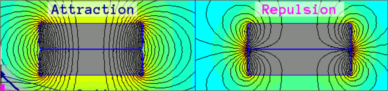
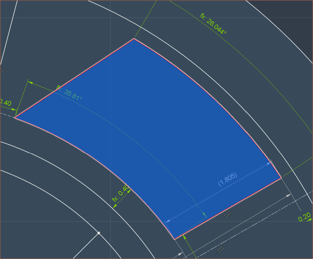 You might be wondering what this is. This is the approximation of 3mm copper foil stacked on itself. Since copper smaller than the magnet width does not provide any torque (so I've heard), it makes more sense for the tape to hug the edges.
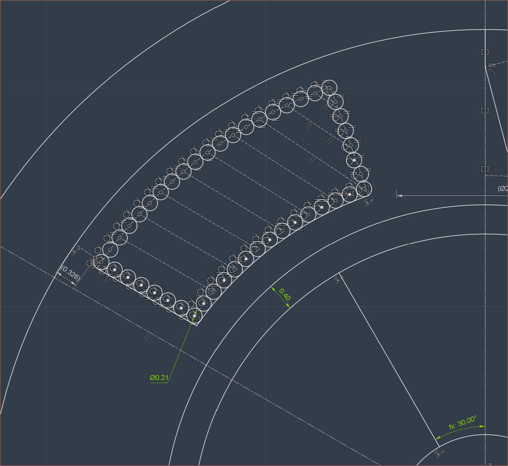


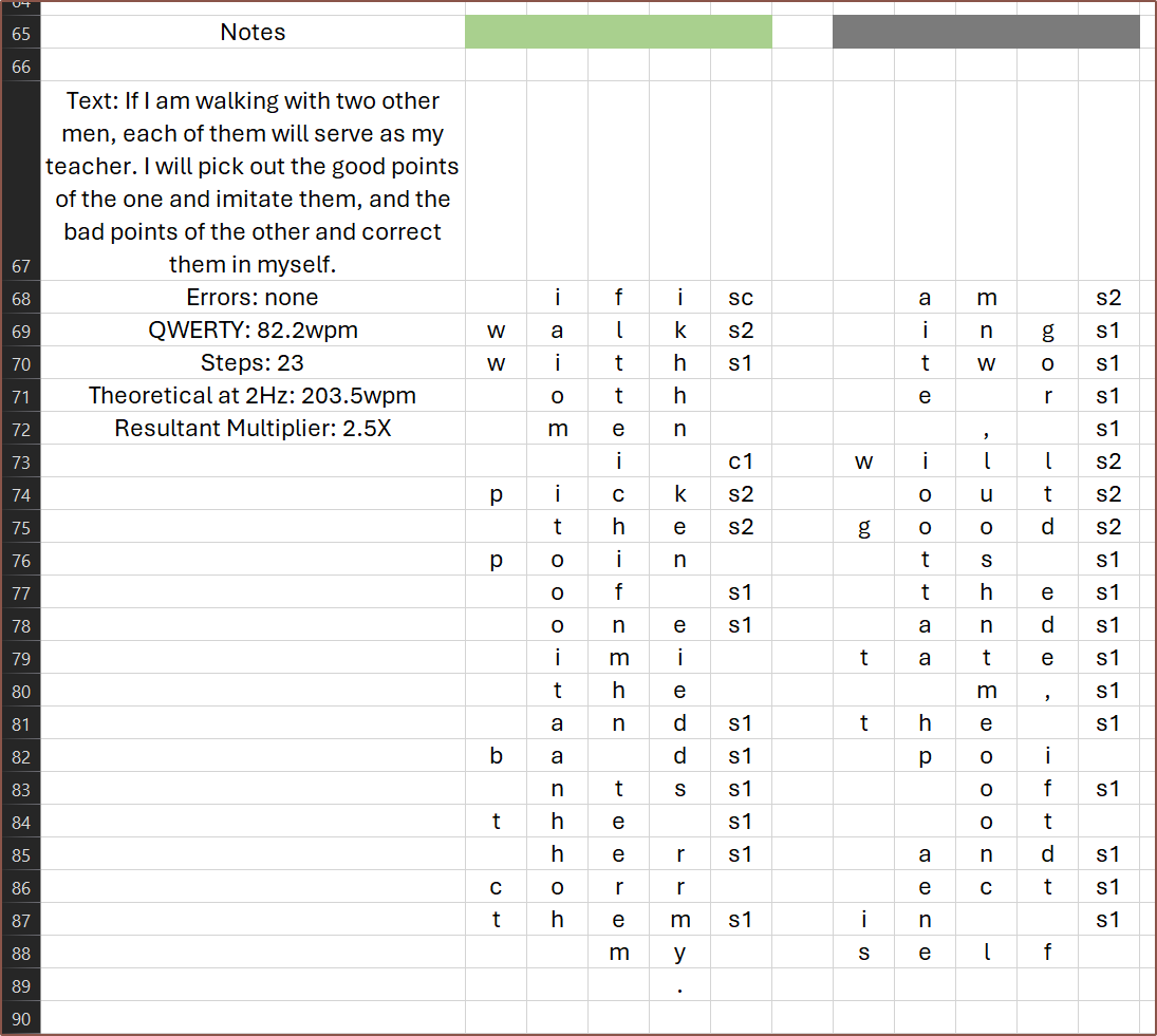
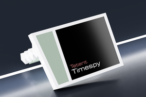
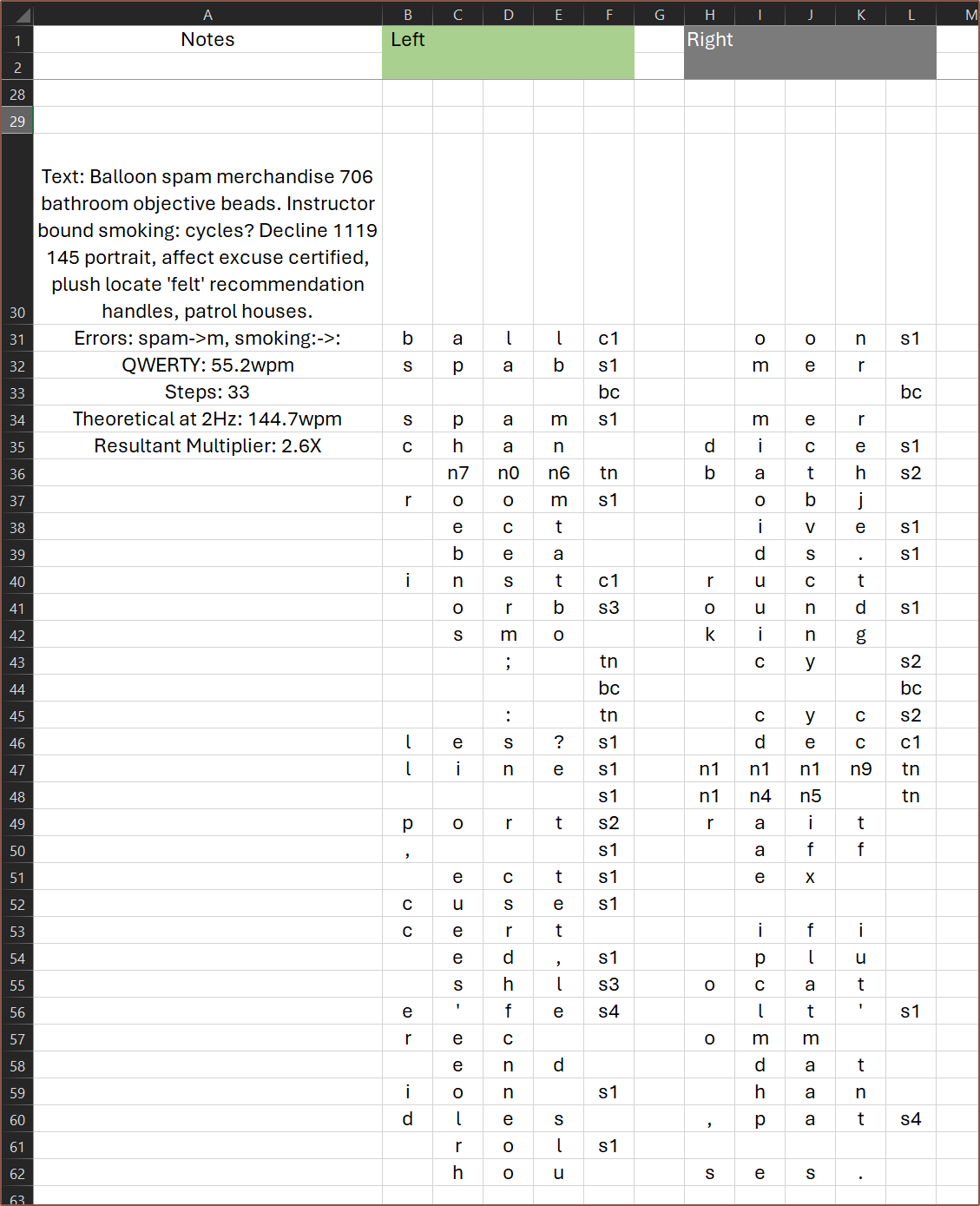 Then I needed another run. I decided to go with a quote this time, and despite it being 5am without having slept yet, I managed to 100-accuracy it.
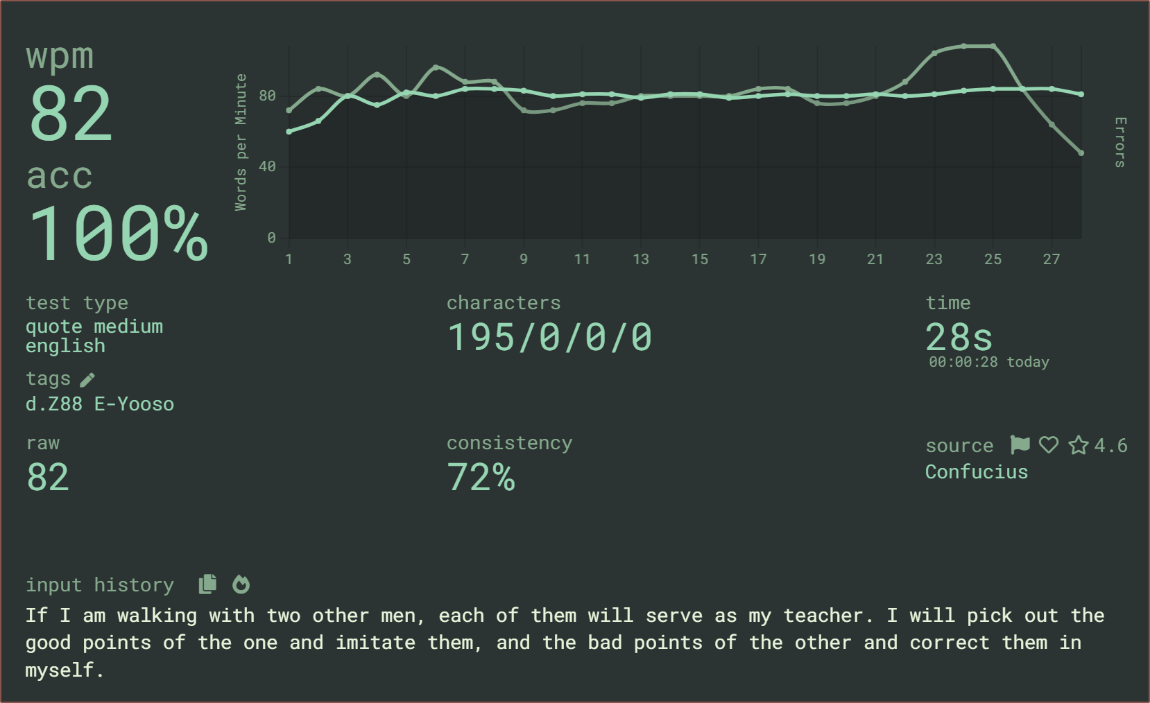


(EDIT: This was supposed to be a reply to the other thread; I don't know what happened)
Well, I love blinkenlichten as much as the next guy, but if I ever made any of these, that would likely be omitted entirely or perhaps replaced by a single WS2812 LED. My ideal input device is something I never have to look at, anyway.
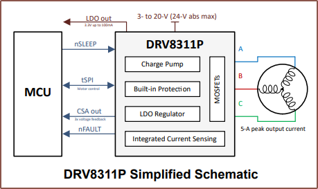
I didn't use the term "voice coils" but that's what a PCB motor (or, really, any electromagnetic motor) boils down to. The whole point of the magnets and (PCB) coils is to eliminate the BLDC motor for haptic/tactile feedback. As I stated, I think the hall-effect sensors would offer good enough position sensing for both motor feedback and reporting motion to the host device.
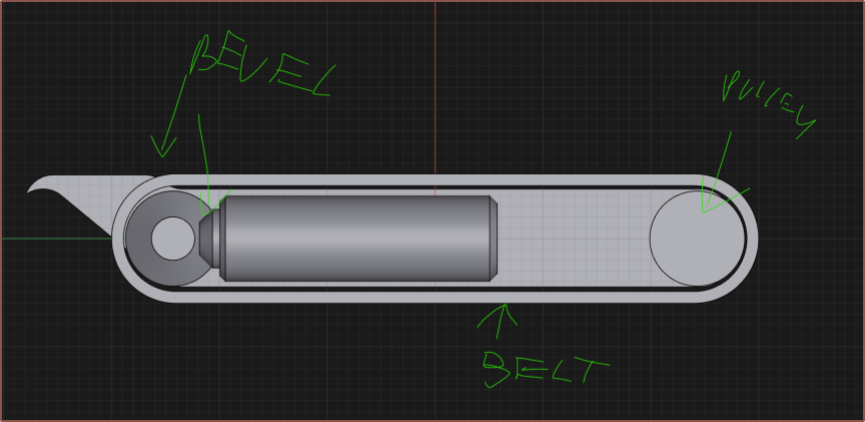
Absolute position would be easy enough to keep track of in software, and I don't see why you would need absolute positioning across power cycles in this application (although I admit I only vaguely understand the concept beyond "one slider per finger that are also analog buttons" at this point). As the "belt motor" would be coreless, I don't think cogging would be an issue.
"Are there any specific optimisations you're trying to achieve with your idea, such as footprint / price / ease of manufacturability?"
It's just a gut feeling, but I think eliminating the rotary motor & mechanics would positively affect all of these, and maybe even improve user experience. (Although I've never tried it, I'm not enthusiastic about trying to drag bead chains across an OLED with my fingertips for any length of time, with or without a 240g opposing force).
Anyway, I was just brainstorming possible alternative ways of achieving the basic idea, not trying to upend the entire project.