elliot
-
Fail Fail Fail Succeed
11/27/2020 at 21:30 • 0 commentsOne morning a few days ago I decided what my workshop lacked was a clock, so thinking this would be a straightforward one day build I set to Work...
I had all the parts I needed, a couple of double digit 7 segment displays, 4 PNP transistors to drive each digit, miscellaneous passives a 3.3V regulator and an ESP8266 module to do the hard work, looking at the data for the module it appeared I had enough gpios to accomplish the task i.e 11 - 4 for digit selects and 7 for segments
So by late afternoon I had made and populated a single sided PCB, all that remained was to program it (my preference for quick projects is to load micropython on the module) , or so I thought...
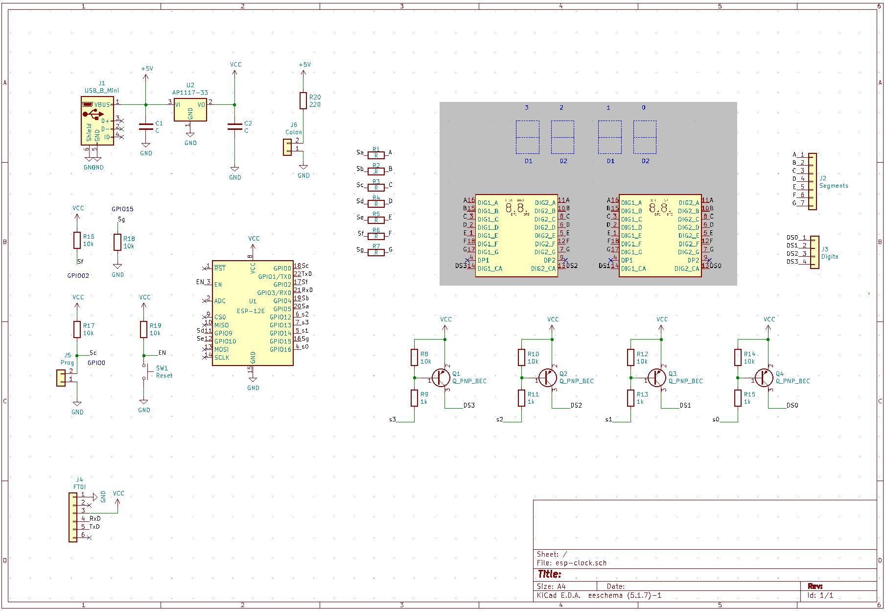
First try schematic:
![]()
and PCB: (note the track on the underside is in reality a wire link)
![]()
I must point out I have used a lot of these modules but have never used more than 9 gpios, I now know there are *only* 9 useable, I knew the MOSI pins were used by the flash memory in the module and had wrongly assumed gpio9 and 10 were available, I was so wrong. Every time I tried to use them the module crashed, after searching online it became quickly obvious that these gpios were unuseable. FAIL ONE.
The solution use a 2-4 decoder for the digit select saving 2 gpios and saving the day, fortunately there was just enough space to fit a sub pcb in the corner of the box, so an hour later I had tacked on a little PCB with a 74AHC139 on it, cut tracks and used vero wire to re-route the board.
Surely it must work now, no such luck the board resolutely refused to start up. I quickly realised my error, in my original design none of the digits are driven at power-up so the pull-down resistor on gpio15 was doing its work but with the decoder one digit would always be driven so gpio15 was being pulled up (gpio15 need to be pulled down for the ESP8266 to start-up). FAIL TWO.
The solution this time was to put an RC network on the 74AHC139 enable pin to delay the digit drive, thus the final schematic:
![]()
And the final pcb with cut tracks, bodge wires kapton tape, tacked on RC and after-thought decoupling for the module power:
![]()
So far so good, loaded the firmware it works! oh dear I wired the 7 segments upside-down, my intention was that the antenna on the module would be pointing down enabling the box to be double sided taped to the shelf. FAIL THREE.
This one was easy to fix in software the gpios needed to be swapped about and the scan reversed.
# number.py

# Display 4 digit number INVERTED
from machine import Pin
from time import sleep_ms

# gpios required for each number
segs = [[12, 13, 2, 5, 4, 0],     # 0
        [13, 2],                  # 1
        [12, 13, 5, 4, 15],       # 2
        [12, 13, 2, 5, 15],       # 3
        [13, 2, 0, 15],           # 4
        [12, 2, 5, 0, 15],        # 5
        [2, 5, 4, 0, 15],         # 6
        [12, 13, 2],              # 7
        [12, 13, 2, 5, 4, 0, 15], # 8
        [12, 13, 2, 0, 15]]       # 9

# digit select = [14, 16]
# NOTE gpio2 connected to Blue LED

# create dictionary mapping gpio number to pins and setting as output
pins = {}
for gpio in [5, 4, 0, 2, 15, 13, 12, 14, 16]:
	p = Pin(gpio, Pin.OUT)      # setup io
	pins[gpio] = p

def dispDigit(value, dig):
      for gpio in segs[8]:	    # segs[8] uses all the segment gpios
            pins[gpio].on()         # turn off all segments (active low)
      pins[14].value(dig & 1)       # select digit
      pins[16].value((dig & 2) >> 1)
      for seg in segs[value]:
            pins[seg].off()         # turn on segments for number

def dispNumber(number):
      for dig in [3, 1, 2, 0]:
            dispDigit(number % 10, dig)
            sleep_ms(5)             # sleep 5ms
            number //= 10
and the main program:
# main.py

from number import dispNumber		# my display driver module
from machine import RTC			# ESP real time clock module
import ntptime				# NTP module
from time import sleep

rtc = RTC()
sleep(1)				# required to stop ntptime error
ntptime.settime()
tm = list(rtc.datetime())[4:6]

while True:
      tmNow = list(rtc.datetime())[4:6]
      if tmNow[1] != tm[1]:		# minute changed so update
            tm = tmNow
            try:
                  ntptime.settime()	# update onboard RTC, done every minute
                                        # because the RTC drifts by 2 seconds per minute!...
Read more »
This user joined on 03/10/2014.