 jperez208
Setting up:
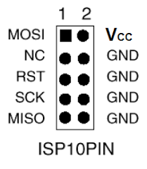
We are going to be setting up our board and programmer using an SPI interface. The USBasp uses a 10 pin connector. The diagram is below. Some programmers use a 6 pin connector. It doesn't really matter which one you use, as long as the correct pins are wired to the correct pins on the microcontroller. Check your documentation for your specific microcontroller for the correct pinouts. The pinouts for both the 10pin and 6 pin connections on the programmer are a bit more universal.
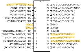
From here we are just going to connect the pins from the connector to the pins of the microcontroller. Again I am using a Atmega88 for this lesson so I've added a picture of the pinouts for that specific microcontroller. Check your documentation for your specific microcontroller. The pins you want to find are labelled:
MOSI: Master Out, Slave in
RST: Reset. This is activated first and puts the microcontroller into programming mode. Put a 10k resistor between this pin and VCC
SCK: Serial Clock. This regulates the data flow between the controller and programmer.
MISO: Master In, Slave Out
VCC: Positive voltage
GND: Ground.
Note: You dont have to connect the Vcc pins to your microcontroller if you have an external power supply powering your circuit. However, you should connect your ground pins to the ground supply of whatever your using for power. Just make sure that your power supply doesn't exceed that of your reccomended limit for your programmer. I dont recommend using more than 5 volts.

note: We generally dont need to use SS (Slave select) when we have a single chip we are programming so this can usually be ignored.
Here is my breadboard set up and ready to use.
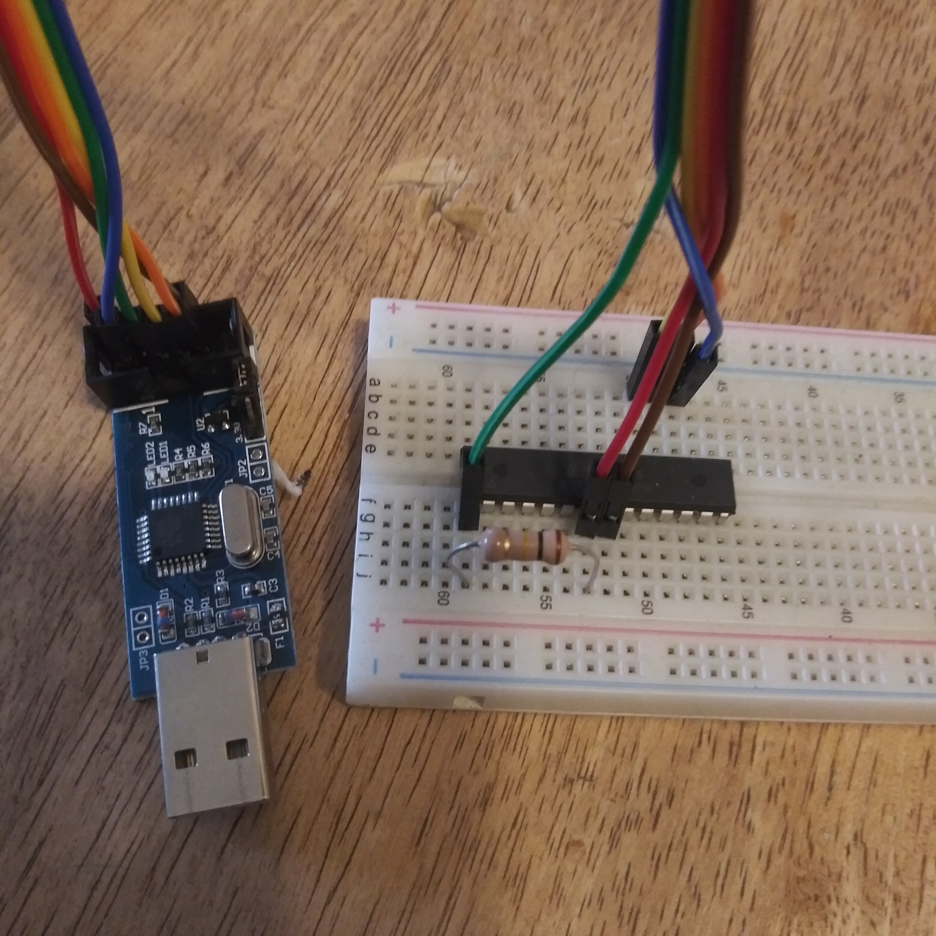
You'll notice I have added the 10k resistor between the Reset and the VCC.
If everything is set up correctly to this point, we are ready to program.
Discussions
Become a Hackaday.io Member
Create an account to leave a comment. Already have an account? Log In.