 jperez208
-
Lets Program!
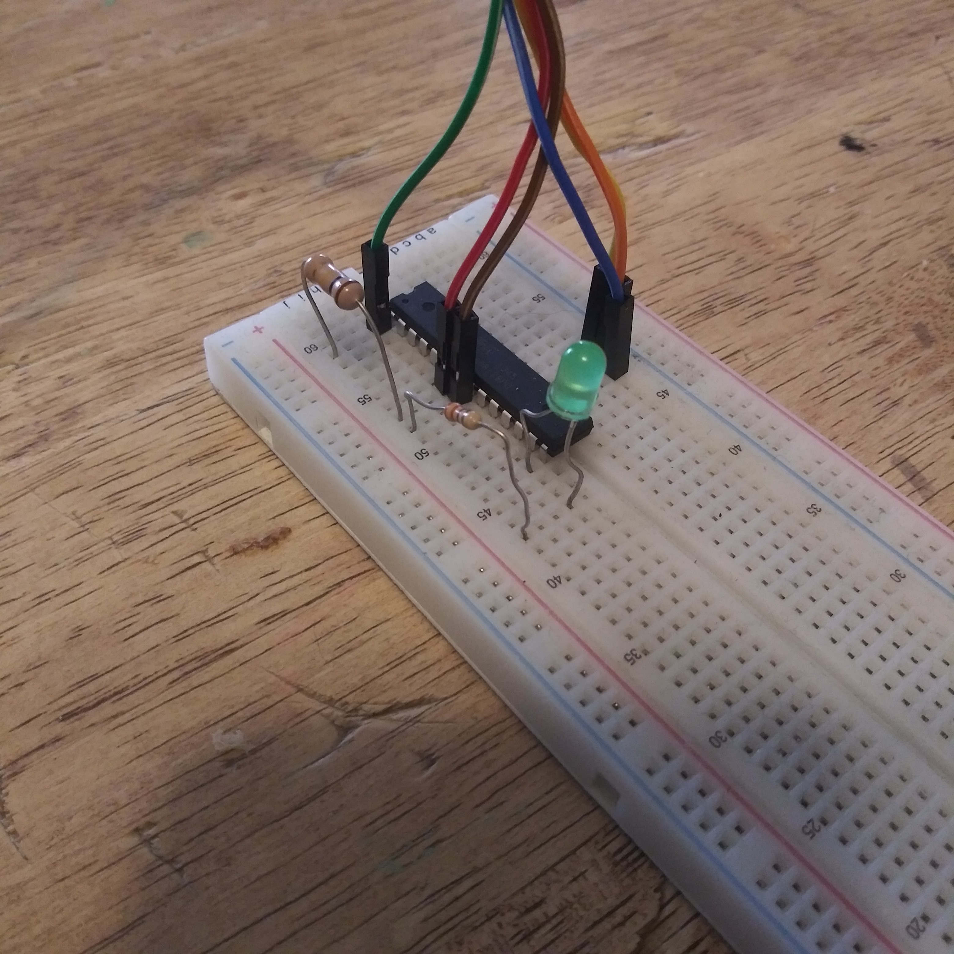
01/23/2022 at 21:46 • 0 commentsSo by now we've done alot of work and still haven't done any actually programming. But dont worry, we are about to get started. First lets connect a LED and 330ohm resistor to the PORTB.0 Pin.
![]()
Open up BASCOM and start a new project/file. It may already be open with a blank page and ready to start typing. First we need to write some parameters that the compiler will use. Its a little much information for some one who has never programmed before but luckily there is a shortcut for this.
![]()
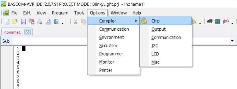
First click options=>compiler=>chip
![]()
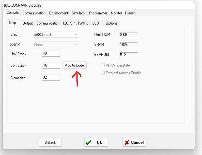
Under chip, find your microcontroller under the drop down menu. These will be slightly cryptic with labels like 2313.dat or m8def.dat. Find the one that most closely matches your microcontroller. Since I am using a Atmega88, I choose m88def.dat. Next click add to code and hit cancel. This code (or similar) should appear at the top of your screen.
$Regfile="m88def.dat" ' specify the used microcontroller
$crystal = 4000000 ' used crystal frequency
$hwstack = 40 ' default use 40 for the hardware stack
$swstack = 16 ' default use 16 for the SW stack
$framesize = 32 ' default use 32 for the frame spaceNext lets type add some code to blink a LED:
' BlinkyLight.bas
$Regfile="m88def.dat" ' specify the used microcontroller
$crystal = 4000000 ' used crystal frequency
$hwstack = 40 ' default use 40 for the hardware stack
$swstack = 16 ' default use 16 for the SW stack
$framesize = 32 ' default use 32 for the frame spaceConfig Portb = output 'Sets Portb as output
_On alias 1 'Alias is used to rename certain values to names that maybe easier to read
_Off alias 0 'later on in the program.LED Alias PORTB.0
Begin: 'Label to start program.
LED = _On 'Turns LED on. Since there was an alias used
'this could also be written as PORTB.0 = 1
Waitms 100 'Wait for 100milliseconds. This time is calculated by the $crystal label in the
'header but the actual hardware clock on your MCU will determine the actual 'blinkrateLED = _Off 'Turns the led off. Could also be written as PORTB.0 = 0
Waitms 100 'Wait for another 100msGoto Begin 'Go back to the label "Begin"
Read more »
'When programming in basic, its a good idea to keep line numbers on.
'The command goto can be used to either find a label in a program
'i.e. GOTO BEGIN or can be used to find a specific line i.e GOTO 16
'Using labels is preferred because if you add code later
'it will move your line numbers around making your goto command point to the
... -
Setting up your breadboard
01/23/2022 at 21:01 • 0 commentsSetting up:
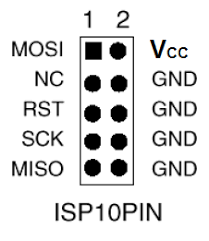
We are going to be setting up our board and programmer using an SPI interface. The USBasp uses a 10 pin connector. The diagram is below. Some programmers use a 6 pin connector. It doesn't really matter which one you use, as long as the correct pins are wired to the correct pins on the microcontroller. Check your documentation for your specific microcontroller for the correct pinouts. The pinouts for both the 10pin and 6 pin connections on the programmer are a bit more universal.
![]()
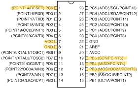
From here we are just going to connect the pins from the connector to the pins of the microcontroller. Again I am using a Atmega88 for this lesson so I've added a picture of the pinouts for that specific microcontroller. Check your documentation for your specific microcontroller. The pins you want to find are labelled:
MOSI: Master Out, Slave in
RST: Reset. This is activated first and puts the microcontroller into programming mode. Put a 10k resistor between this pin and VCC
SCK: Serial Clock. This regulates the data flow between the controller and programmer.
MISO: Master In, Slave Out
VCC: Positive voltage
GND: Ground.
Note: You dont have to connect the Vcc pins to your microcontroller if you have an external power supply powering your circuit. However, you should connect your ground pins to the ground supply of whatever your using for power. Just make sure that your power supply doesn't exceed that of your reccomended limit for your programmer. I dont recommend using more than 5 volts.
![]()
![]()
note: We generally dont need to use SS (Slave select) when we have a single chip we are programming so this can usually be ignored.
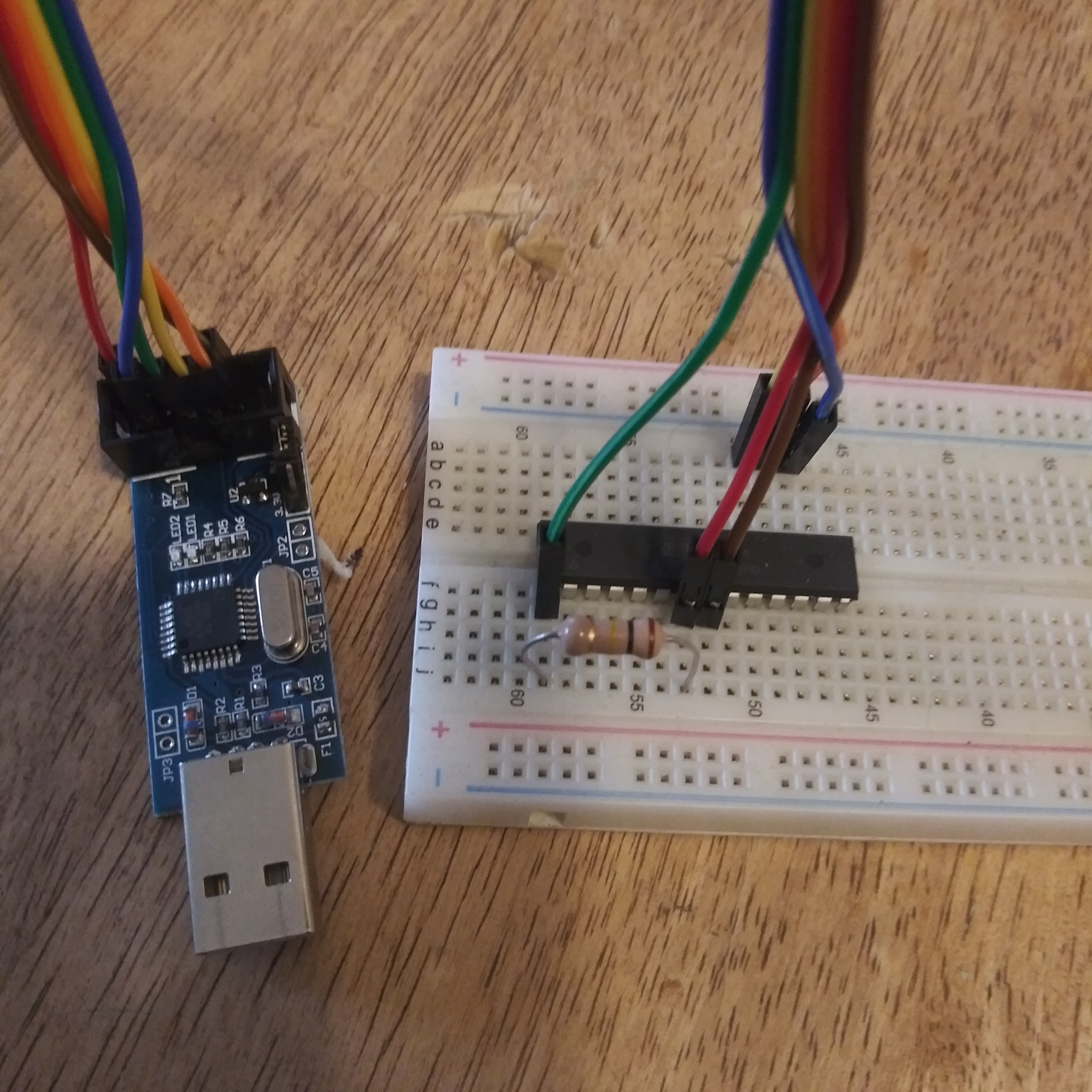
Here is my breadboard set up and ready to use.
![]()
You'll notice I have added the 10k resistor between the Reset and the VCC.
If everything is set up correctly to this point, we are ready to program.
-
Using BASCOM-Avr
01/23/2022 at 20:07 • 0 commentsGetting Statrted...
Before we can start programming any microcontroller, we need to set up a few things first. In this lesson, I'll be using a Atmega88 and a USBasp programmer. The same basic principles can be used with most microcontrollers using an SPI ( Serial Peripheral Interface).
First we need to obtain a programmer. A programmer is a stand alone board that acts as a buffer between the computer your writing your code on and the chip you wish to program. Theres more to it than that, but for right now to get started, you need a programmer. I bought this one from amazon and it works pretty well. Just make sure you follow the instructions listed to install a driver.
https://www.amazon.com/HiLetgo-ATMEGA8-Programmer-USBasp-Cable/dp/B00AX4WQ00
After that you'll need an actually program to write your code in. This can be as simple as using notepad or another text editor and a compiler. This can be a little complicated to use and set up but fortunately there are many software programs that wrap all of this up into a nice package. Since we are going to be using the language BASIC, I am going to be using BASCOM-AVR.
You can download it here : https://www.mcselec.com/index.php?option=com_docman&task=cat_view&gid=99&Itemid=54
Scroll down and find the BASCOM-AVR demo version and download that. For most purposes, the demo version will cover most everything you need.
You should have everything you need to get started now. (provided you already have a breadboard, wires, LEDs, resistors etc.) Lets get to wiring!

 shlonkin
 genericsoma
 Lutetium
 arko
arko Mattia Dal Ben
 Val
Val deʃhipu
 Jochen Alt
 brashtim
 Nicholas Stedman
 James Hobson
 atomkemp
 Keith Elliott
 Ekawahyu Susilo
 jorisplusplus
 hominidae
 haydn jones