This project uses this great tutorial as a starting point. You should read it. Seriously, it's way better than anything I could write.
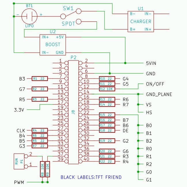
I did make one modification though: I used 16 bit addressing instead of 18 bit so a few more GPIOs were freed up. Specifically SPI and a PWM channel.
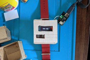
One thing I love about the Zero is it's flat back. It means mounting it often consists of a strip of double-sided foam tape. This project uses this mounting method for the Zero and several other boards extensively.
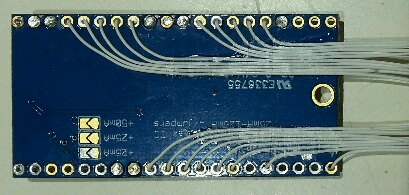
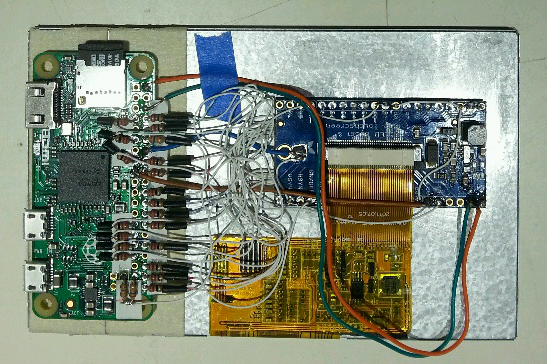 Everything is mounted with doube-sided foam tape. The tape under the TFT Friend is trimmed to avoid the wires on the back.

 Giovanni
 Maso
Maso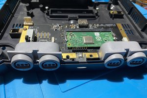
 jackal123uk
Hi Mincepi, Thank you for this tutorial, this is awesome !!
Could you provide more details on how to add the lcd565.c to/lib/modules? Should it be copied just there or does it needs to be compiled? I'm trying this setup with a Pi Zero and a 5" TFT display but I am stuck at this last stage.
Thanks :)
Covert