Close
0%
0%

Shakelet - alerts for the hard of hearing

A wireless vibrating wristband to notify hard of hearing people of telephones, doorbells and other sound alerts.

Similar projects worth following
People who are hard of hearing often have difficulties with standard consumer technology. So many products rely upon audio alerts, whether they be doorbells, telephones, washing machines or dishwashers.

The intention behind this project is to create a vibrating wristband that would be linked by 2.4GHZ RF transceivers to a series of audio sensors. These sensors would be attached to any products that use audio alerts. When an alert is triggered, the wristband will vibrate. There will also be a single RGB LED which will change colour depending upon which of the sensors has been triggered.

Whilst alternative doorbells and telephones exist for the hard of hearing, they are often expensive (c. $300) and (to be blunt) ugly. This project would allow the user to purchase standard products and adapt them to their requirements.

The challenges I anticipate encountering are:

- Dealing with multiple alarms triggered simultaneously; and
- Powering the sensors and wristband.

Alex's Library.lbr

Library with custom Eagle CAD parts for NRF24L01 mini board, CR2032 battery clip and vibrating motor.

lbr - 25.42 kB - 10/02/2016 at 14:24

Download

sch - 601.19 kB - 10/02/2016 at 14:24

Download

sch - 480.59 kB - 10/02/2016 at 14:24

Download

brd - 265.53 kB - 10/02/2016 at 14:24

Download

brd - 266.08 kB - 10/02/2016 at 14:24

Download

View all 7 files

  • 2 × PCBs (see gerber files in zip file)
  • 2 × atmega168p QFNP Microprocessors, Microcontrollers, DSPs / Microcontrollers (MCUs)
  • 2 × nrf24l01+ modules (SMD mini boards or through hole)
  • 1 × Vibrating motor disk (SMD or through hole)
  • 1 × 27mm piezo disk

View all 14 components

  • Video killed the radio star

    Alex Hunt10/02/2016 at 14:30 0 comments

    If you want to see an awkward Englishman presenting a YouTube video, here's your chance! This is my attempt at explaining and demonstrating the project in video format. Enjoy!

  • Write up and project files now available

    Alex Hunt10/01/2016 at 14:12 0 comments

    I have spent a bit of time producing a write up of this project, not least for my own benefit so that when I look back in a few months time I can remember how everything works. The write up is availalble in the ZIP folder attached to this project (along with all of the other files) and also on GitHub here.

    I have also taken a few photos of the soldered boards. Ideally I would like to make the bracelet board a little smaller. The limiting factor is the size of the coin battery holder on the rear. The size of each board is around 4cm squared (c. 1.5 inches).

    Bracelet board

    Sensor board

  • Prototype time

    Alex Hunt08/23/2016 at 07:29 0 comments

    Since receiving my first PCBs there has been a flurry of activity. Naturally, the first thing I did was to solder one up:

    Having never used SMD components before I was pretty pleased with the results. For the moment I am attaching the Piezo sensor with crocodile clips to the top two holes. The wires on them are quite delicate and I was concerned they would break. After an anxious few minutes uploading the code, I am delighted to report that it works!

    Light-headed with success I decided to complete the PCB design for the bracelet part. Having learnt a lot from my first experience, I was feeling slightly more ambitious and this is what I came up with:

    I decided to break out the RX and TX pins to help with testing and also some other unused pins as I have a vague plan to add a button in future for muting the bracelet.

    By this point I was overcome by confidence and decided to update the sensor board as well. I have swapped the large NRF24L01 for one of the mini-boards, added an LED (again, future plans for this) and broke out a couple of pins. Finally I decided to panelise my designs and also add in a couple of extra boards to make programming the DIP ATMEGAs and TINYs easier.

    Now it's off to the folk at smart-prototyping to work their magic. I used Maker Studio for the first round of boards and was delighted with the results. However, smart-prototyping offer slightly cheaper express delivery and so I'm going to give them a shot.

    So what's left to do? A few things spring immediately to mind:

    • Optimise code for power consumption (the sensor eats through a watch battery in about 2 hours with the current simple code);
    • Add a wifi bridge to the network of sensors to allow smartphone notifications;
    • Design some sort of case for the bracelet / sensor boards.

    Other suggestions are always welcome.

  • Boarderline ecstatic

    Alex Hunt08/17/2016 at 07:41 0 comments

    The sensor boards have arrived!

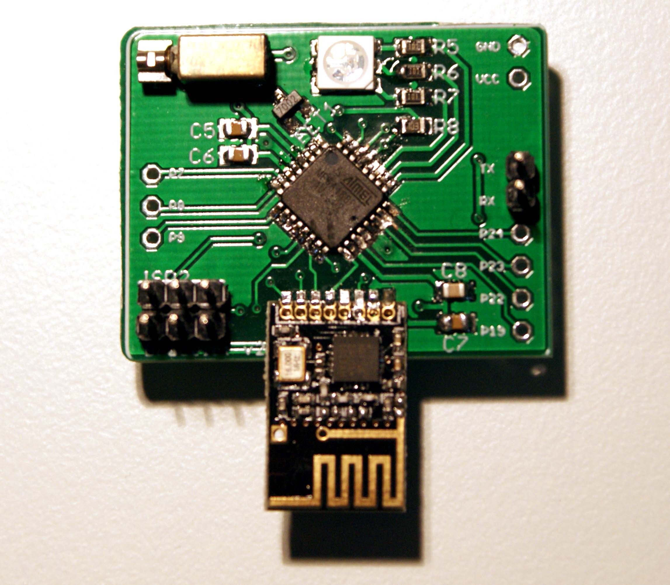
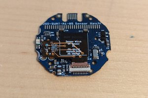
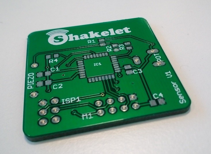
    Being my first ever PCB I am unreasonably excited about this. A huge thanks to Gabe Buckmaster for his generous help and wisdom with the design - it looks much better than my first attempt and I have learnt a huge amount. Time to crack out the soldering iron.

  • Gerber load of this guy!

    Alex Hunt07/16/2016 at 17:56 0 comments

    Although there has been radio silence for a few weeks, I have been working hard(ish) on the project. Today I designed my very first PCB, which is the sensor part of the project.

    The full PCB file can be found in the documents section and I would love and feedback anybody would care to give! In particular, I'm slightly concerned that pin 6 isn't connected to ground, although Eagle did not throw up any errors.

    One addition to the circuit is a potentiometer in the top right. I am using this to provide a threshold to the AVR to use for sensitivity adjustments. The code is now much improved and I will upload in the next couple of weeks.

    Next step, the bracelet PCB!

  • Code time!

    Alex Hunt06/12/2016 at 15:08 0 comments

    I have finally got round to putting my draft code online (GitHub). This is probably the weakest part of the project at the moment. In this post I will concentrate on the issues with the sensor code. Here is the full main.c:

    // ------- Preamble -------- //
    #include <avr/io.h>                  	// Defines pins, ports, etc
    #include <util/delay.h>            		// Functions to waste time
    #include <stdlib.h>
    #include "pinDefines.h"
    #include "piezo.h"
    #include "nrf24l01.h"
    #include <avr/interrupt.h>
    
    volatile uint16_t adcValue = 0;
    volatile uint16_t middleValue = 511;
    volatile uint16_t highValue = 520;
    volatile uint16_t lowValue = 500;
    volatile uint16_t noiseVolume = 0;
    volatile uint8_t padding = 20;
    volatile uint8_t ADCCount = 0;
    
    void sendSignal(void){
    	initNRF24L01();
    	
    	//Reset MOSI pin (PB0) to allow signal to be sent again
    	RF_DDR &= ~(1<<RF_MOSI);
    	RF_PORT|= (1<<RF_MOSI);
    	
    	reset();
    	uint8_t W_buffer;
    	W_buffer=0x01;
    	
    	int retries; //Send signal multiple times
    	for (retries=0;retries<5;retries++){
    		transmit_payload(W_buffer);
    	}
    }
    
    
    ISR(ADC_vect){
    	//Shift result left by 8 bits as using left align - allows full 10 bits to be captured
    	adcValue = ADCH;
    		
    	// moving average -- tracks sensor's bias voltage
    	middleValue = adcValue + middleValue - ((middleValue - 8) >> 4);
    	
    	// moving averages for positive and negative parts of signal
    	if (adcValue > (middleValue >> 4)) {
    		highValue = adcValue + highValue - ((highValue - 8) >> 4);
    	}
    	if (adcValue < (middleValue >> 4)) {
    		lowValue = adcValue + lowValue - ((lowValue - 8) >> 4);
    	}
    	
    	// "padding" provides a minimum value for the noise volume
    	noiseVolume = highValue - lowValue + padding;
    	
    		// Now check to see if ADC value above or below thresholds 
    		// Comparison with >> 4 b/c EWMA is on different scale 
    		if (adcValue < ((middleValue - noiseVolume) >> 4)) {
    			sendSignal();
    		}
    		else if (adcValue > ((middleValue + noiseVolume) >> 4)) {
    			
    			sendSignal();
    		
    	}
    }
    
    
    int main(void) 
    {
    	
    	initSPI();
    	initADC();
    	initNRF24L01();
    	
      while(1)
      {
    	if (adcValue>2000){
    		sendSignal();
    	}
    	
      }
    
      return 0;
    }

    ADC ISR is intended to use an exponentially weighted moving average for assessing when the ADC value is significantly high enough. The key parts were taken from the excellent book Make: AVR Programming by Elliott Williams (available on amazon.co.uk) which was my gateway drug into this hobby and which I really can't recommend highly enough.

    The ADC is running in free-running mode. However, as I haven't yet looked at how to put the attiny into sleep mode whilst keeping the ADC running, I have fudged the main loop at the moment by just including a conditional statement that can never be met. This is something I hope to correct over the next week as it is clearly not an efficient way to program.

    The other thing you will notice is that the data sent is just a random buffer. Eventually I will send a separate identification code for each sensor so that the bracelet will be able to determine which one has been triggered. However, for reasons I can't quite work out the data received by the bracelet is not the same as that being sent so this is again an issue that needs looking at.

    The bracelet is another hornet's nest of patchy coding and I will turn my attention to this once I am happy with the sensor side. The list of things to do seems to be getting longer!

  • Fritzing brilliant!

    Alex Hunt06/09/2016 at 21:06 0 comments

    9 June

    I think I'm getting the hang of this circuit diagram business now. Here are the ones for the bracelet side of the system. Next stop - code (ohh err...)!

    In other news, it turns out that the name "Vibracelet" has been used before commercially. A new name is therefore in order. I have gone for "Shakelet" for now due to coming up with nothing better. Maybe inspiration will strike. Please do let me know if you have any ideas!!

  • I would like to thank my mum...

    Alex Hunt06/08/2016 at 22:07 0 comments

    8 June

    I have always wondered what I would say if I won an Oscar and for me getting through to the Hackaday competition final is about as close as I will ever come! Just like a self-absorbed Hollywood actor, I would like to put down a few words to mark the occasion. I am shocked and humbled to have made it through. There are so many fantastic projects out there that it comes as a huge surprise that my slightly amateurish attempt has made it. Thank you to everybody who has taken an interest in what I am trying to achieve!

    Anyway, I promised that my next post would include a circuit diagram and I am a man of my word. I have started with the sensor diagram and will produce the bracelet diagram over the weekend.

    The next step will be cleaning up my code and trying to get around the problem with the CE pin on the RF transceiver which has been bugging me for some time. Once that has been done it will be time to start designing cases for everything, which is completely uncharted territory for me. I may also need to give some thought to whether the NRF24 is the right transceiver for the finished product once range and size considerations have been taken into account. Time to get reading up on designing PCBs!

  • I got 99 problems...

    Alex Hunt05/29/2016 at 19:52 0 comments

    but a switch ain't one!

    Before I get ahead of myself and work on designing a PCB and sensor cases / bracelets, I thought I should have a quick recap of the challenges that lay ahead. This is therefore a reasonably comprehensive list of difficulties that I have come across but (so far) ignored and how I think they might be overcome. Any advice would be most welcome.

    1. Sensitivity adjustments - the piezo setup is temperamental at best. Sensitivity is currently adjust in the software but I need a way to adjust manually. Obviously a circuit diagram would help with this - it's next on my list - I promise!
    2. Multiplexing the CE pin on the NRF24L01 - I have been thinking about this a lot over the last week and have not found a way to properly do this. Quite simply, I have run out of pins on the ATTiny. I will have a look at power usage but I may simply change to another ATMega168. This would also make the wireless coding easier as it would be the same for both receiver and transmitter.
    3. Data transfer - the data being sent from the sensor does not appear to the be same as that received by the bracelet. This has made it impossible so far to use multiple sensor. I need to have see what is going on with my serial dongle.
    4. Minaturisation - I have never used SMD components before and have the dexterity of an elephant. Lots of soldering practice will be needed!
    5. Power supply - The plan is to run both the sensors and bracelet off CR2302 batteries. Both MCUs will need to be run on minimal current but I am not sure how much battery life I will get out of either. I was hoping for a minimum of 6 months for each.

    The next post will definitely include my circuit diagram!

  • Vibracelet - working protoype

    Alex Hunt05/20/2016 at 13:31 0 comments

    20 May 2016

    After a frustrating few days I have finally got the Vibracelet working. There were two problems to note:

    1. Sensitivity of the piezo sensor; and
    2. Wiring of the attiny85.

    The piezo sensor was nowhere near sensitive enough to pick up normal level sounds from a mobile phone or doorbell. However, I finally managed to solve this by using an exponentially weighted moving average in the ADC code of the attiny. The sensitivity still needs some adjustment and a method of adjusting/calibrating on the fly but that can wait for another day.

    The difficulty with the wiring resulted from a lack of pins on the attiny. I solved this by tying the CE pin of the NRF24L01 to VCC (3.3v). This isn't ideal as it will increase battery drain but I will look at ways of multiplexing the CE pin later. If I can find no other solutions I may need to change my microcontroller. Any suggestions are gladly welcome.

    Finally, I took a short video to show it working in all its glory. There is still a lot to do but I am pleased with progress to date.

    Great Success!! Anyway, I had best tidy up before my wife realises I have mutilated her doorbell...

View all 12 project logs

  • 1
    Step 1

    Download gerber files from the zip file included in the project documents and send to your local fab lab to print.

  • 2
    Step 2

    Order components in component list.

  • 3
    Step 3

    Solder components (I used a cheap hot air station)

View all 7 instructions

Enjoy this project?

Share

Discussions

Arya wrote 06/06/2016 at 19:20 point

Wonderful project! Congrats on being funded! I can't wait to see some code =)

  Are you sure? yes | no

Alex Hunt wrote 06/08/2016 at 22:11 point

Thanks Aresnijs!  The code is in a slightly sorry state at the moment but it's coming soon - I promise!

  Are you sure? yes | no

Similar Projects

Does this project spark your interest?

Become a member to follow this project and never miss any updates