 amandaghassaei
This controller does all its app processing itself, it does not rely on a computer to process button presses/analog controls into MIDI. This means you can plug it directly into a synth or any device that understands MIDI and you're good to go, no computer required. It runs off a beefy LiPo battery that keeps it running for days on a charge, so it's fairly portable as well. It's totally open source and can be adapted to your particular audio setup/needs. All the Arduino code is up on github (click the cloud-shaped button to download), along with a MaxMSP patch that decodes data from the controller into something usable in Max.
An overview of the apps I've written so far:

Pixel Tilt - One pixel moves across a 2D keyboard with tilt, triggering MIDI as it moves. Control velocity and basenote with pots.
Flin - Music Box app based on monome. Speed and velocity of notes controlled by y tilt. Paging across 16 "lanes" with pot. Shake to erase.
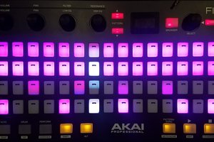
Serial Communication with MaxMSP - Pull data from buttons and analog controls into MaxMSP and use Max to send LED states. Supports 5 bit analog controls for x/y accelerometer and 2 pots. This is great if you want to run audio processing applications with the controller. Download SerialDemo app (SerialDemo.maxpat, included with the Arduino files, click the cloud-shaped button here) to parse data in Max. Beat slicer (shown above) app is included with the Arduino files as well.
Arpeggiator - Plays a two, three, or four note arpeggio, similar to this app I wrote for monome. One pot controls the speed of the arpeggio, another controls velocity. Notes within the arpeggio can be shifted up or down by one semitone via button controls. The whole arpeggio is transposed via x tilt. Press the leftmost note in the arpeggio to play the notes in ascending order, press the rightmost note in the arpeggio to play the notes in descending order, and press a middle note in the arpeggio to play the notes in a random order. Shake to erase.


Boiing - Bouncing pixels that generate polyrhythms, based on this tenori-on app. Bounce direction based on y tilt. Speed and MIDI velocity (loudness) controlled by pots. Shake to erase.

Step Sequencer - Four note 16 step sequencer. Pots control tempo and paging across sequence. Shake to erase.
MIDI Keyboard - Simple MIDI keypad. Control velocity and basenote with pots, pitchbend with x tilt.
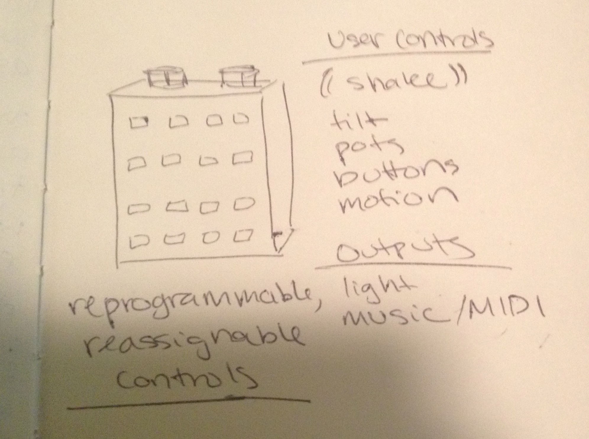
System design:


 AndrewMcDan
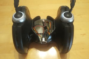
 Edwin Meijne
 Po8aster
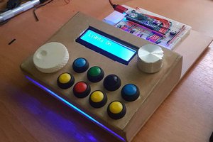
 Victor Frost