Oskar Weigl
-
Hobby motors in your robots
05/08/2016 at 15:02 • 16 commentsI'm not a mechanical engineer. So what follows is probably not the neatest or most optimal solution. In fact, I would love to see a project with some improved setup. Nevertheless, I would like to share with you what I have learned from using these motors in my robots.
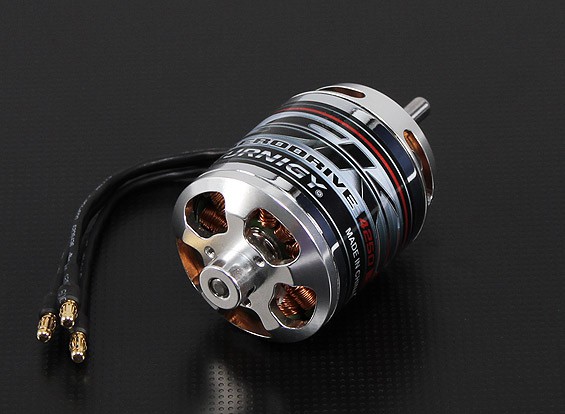
My favorite type of motor (so far) for robotics applications are the Turnigy Aerodrive SK3 series.
![]()
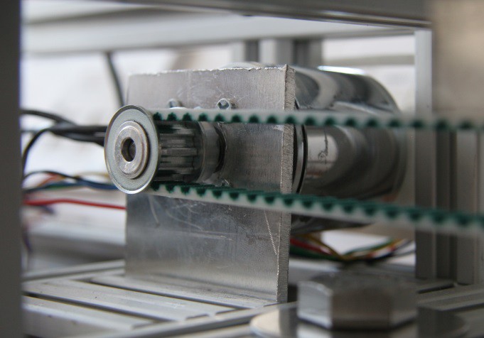
This is for several reasons. Apart from the things that almost all hobby motors have, which is low cost and high power, is that it has a low kv number (more on that later), and has the main shaft coming out of the "back" of the motor. If you look at the above picture, you can see that the mounting plate is on the same side as the shaft. This means that if you attach a pulley to the shaft, and pull sideways on it with a belt, the leverage from the bearing to the pulley is as short as possible. See the below image (which is from the rig you can see in the 3rd demo video) for an idea of what I mean:
![]()
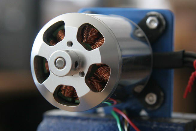
Another great thing is that they give you the possibility to mount something on the spinning side too. The motor even comes with an adapter that attaches to the seen trio of tapped holes and gives you a shaft:
![]()
This is perfect for attaching the encoder:
![]()
For your convenience, I compiled this table of motors that I have had good experience with. The motor used above is the Turnigy Aerodrive SK3 - 4250-350kv.
Motor Price
$Power rating
WPeak Torque
NmWeight
kgHobbyKing Donkey ST4010-820kv 13 700 1.21 0.19 Turnigy L3040A-480G 20 1,000 1.79 0.19 Turnigy Aerodrive SK3 - 4250-350kv 36 1,200 2.36 0.27 Turnigy Aerodrive SK3 - 5065-236kv 56 1,850 4.21 0.53 Turnigy Aerodrive SK3 - 6374-149kv 80 2,250 7.77 0.84
Pick your motor!I made this spreadsheet to help you pick out a motor for your project. Let me know if there is something that needs explaining, or adding.
-
Surface mount soldering: Easier than you might expect.
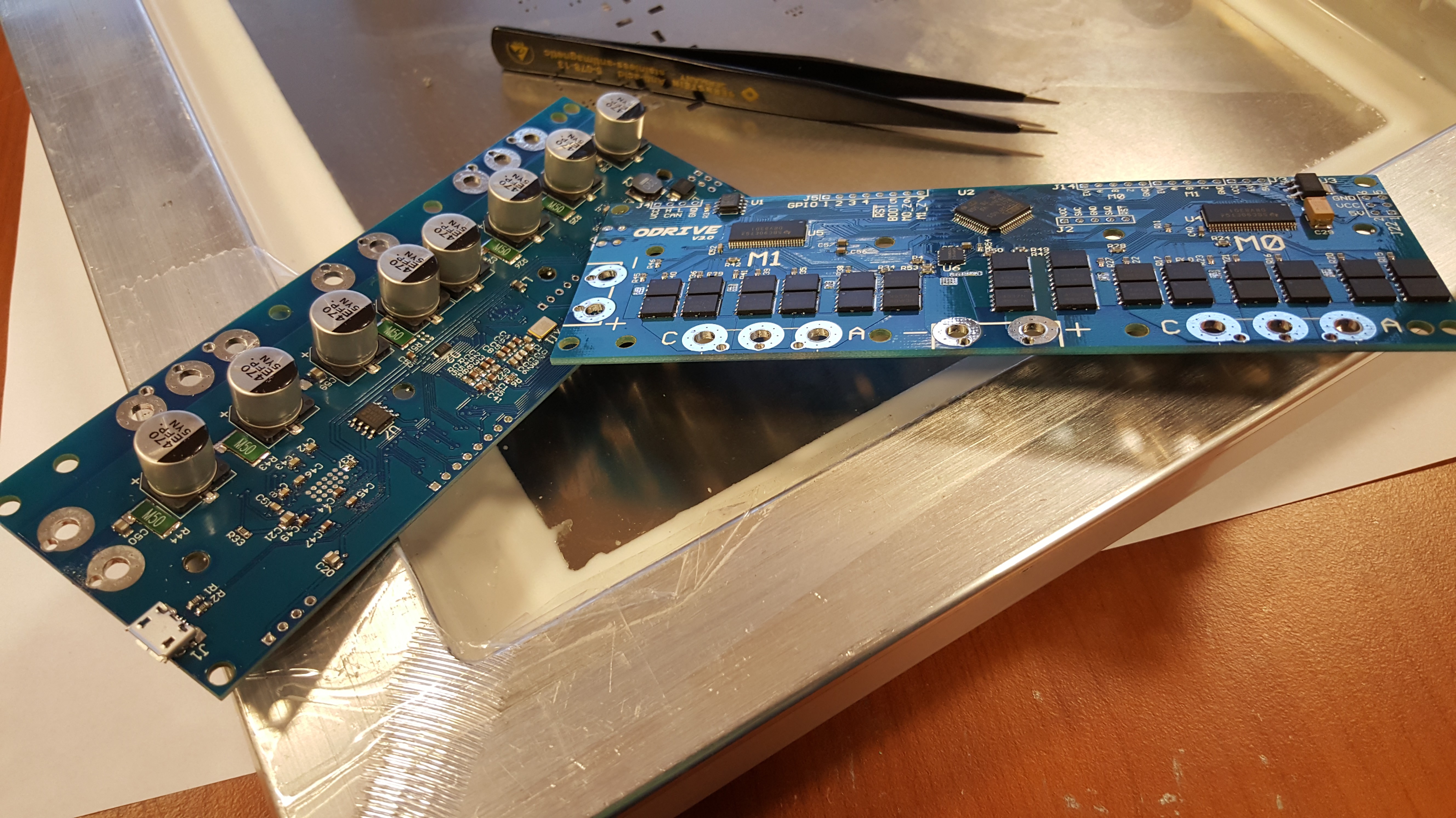
05/10/2016 at 11:52 • 0 commentsThe design of the ODrive is almost entirely surface mount, the only exceptions being some of the heavy duty screw terminals and a couple of rows of headers for IO. This design choice is likely not a surprise to most of you, SMD's are usually cheaper, more compact, easier for industrial production and sometimes the components we want aren't available in any other way!
So SMD it is! However this does pose hobbyists a bit of a predicament. Most people have not done any serious construction with SMD's and they (quite reasonably) think they are a hassle to deal with: this post is about dispelling some of those worries.
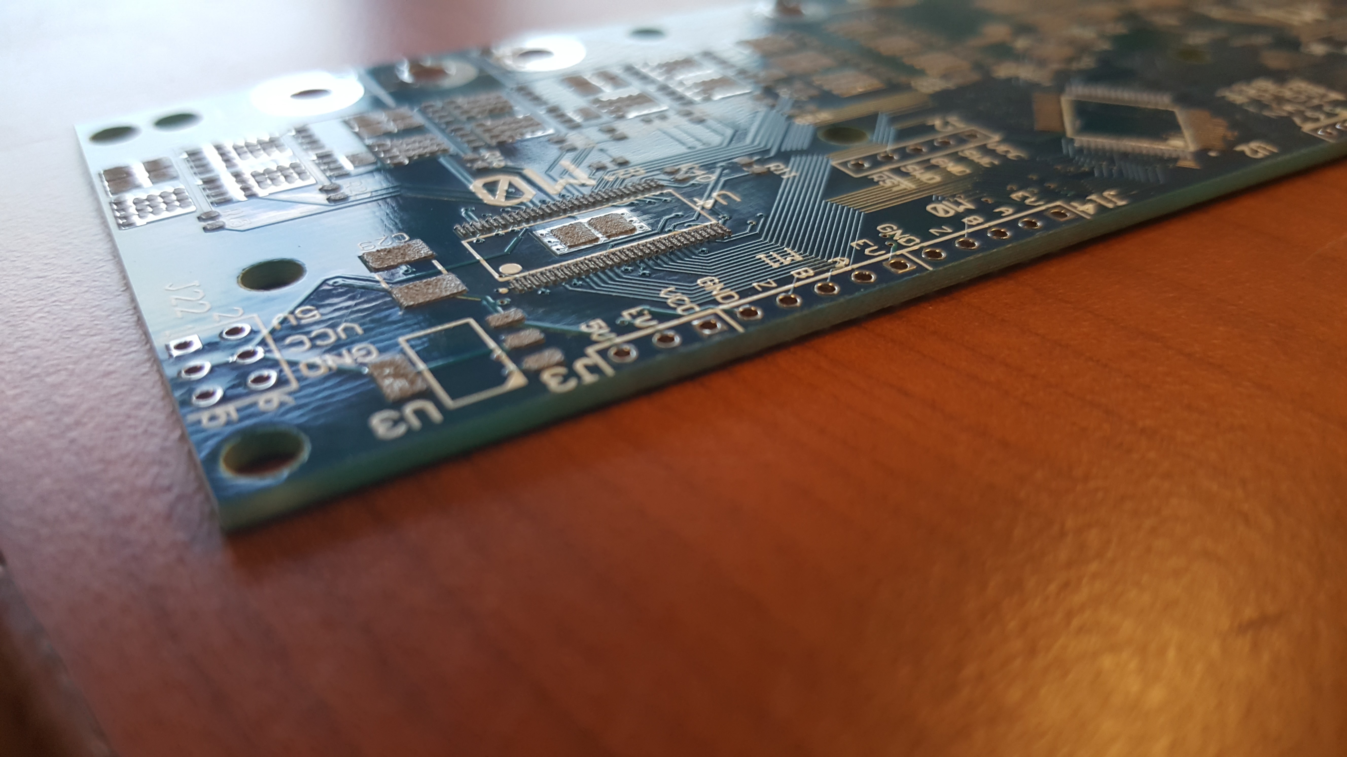
Before any soldering can happen, something to solder onto must be acquired. The PCB in this project is only 2 layered, so it could be home-brewed if you are skillful, but we would strongly recommend against that. There are many vias that need plated through hole (PTH), many 0603's in close proximity that pretty much require a decent solder mask and many of the tracks are very thin. Though I think the main reason for going for a 'proper' PCB is that thanks to the hobbyists constantly demanding more quality for less cost from PCB houses, they are very cheap to get manufactured. You can get 10 copies of this board from china for $35 + postage, pretty epic, though there are some extras you should seriously consider adding if your budget allows.
- Extra copper thickness: Most board houses will offer '2oz' copper, which is twice as thick as the standard offering, if you are going to push the board to the limit (and we hope you do) this will help the board handle the 100s of Amps without overheating/burning out. Though you can skip this option depending on the particular application you have in mind.
- Steel solder stencil: All decent board houses will offer you the option to get a steel stencil, where both sides of the board will be put on the same stencil. The stencil varies in cost with manufacturer, ours was $18. This will make your life much easier, though of course there are many ways to skin a cat; you can also use home made stencils using a laser cutter, or commit some time with a solder paste syringe and develop beasty hand muscles ;)
- Coloured solder mask: Why, because sex appeal, that's why.
With the above things in mind we can strongly recommend Elecrow, primarily because their stencils are cheap, but all of the other optional extras are also on par with other board houses. The quality is very good, but nowadays that goes for all of the major board houses catering to hobbyists.
You have your shiny new board, and have ordered the required components from your local supplier (Farnell and RS are good choices in most countries). Time to get soldering! The most important step to get right is applying the solder paste. Having the right amount of paste will save you from most of the pitfalls, as long as the gods of surface tension are on your side. Place your board on the table and surround it with all the spare boards. Have a friend hold the stencil down whilst you pull a bead of solder paste across all the holes with an old credit card, try and get all the holes filled in one swipe, then scrape backwards such that the stencil is mostly shiny steel again. Order obedient friend to lift the stencil straight up. This should leave perfect little blobs of solder, wipe off and start again if there is lots of blobbing.
The stencil and board as supplied from Elecrow.
![]()
Nice, square, separated solder piles. Brings a tear to my eye.
![]()
When you are satisfied with your pasting, we can now move onto pick and placing. In industry this is usually done with a big expensive machine, but for us, obedient friend to the rescue! I jest, you can do this yourself, but it is more fun to do it with a friend. One of you can dispense the components, dictate where they should go. The other can spend their time placing the components with tweezers and trying not to smoosh the whole lot with their wrist.
Three at a time baby, yeah!
![]()
Once all of the components are on the board (one side only) we need to melt all the solder to make the joints. We used a fairly 'proper' soldering oven, which hopefully your hackspace would have, but others use modified toaster ovens or just hot air guns. What ever method you choose, the goal is the same: Make hot, melt solder, wait to cool.
Like a proud mother giving birth!
![]()
Repeat on the other side. You will need to raise the board up on a sheet of wood or similar to stop the components touching the table when you are stencilling. When you put it in the oven again you don't need to worry about the other side, surface tension has got your back.
Finally you need to check the board over carefully for errors. There is likely to be a short or two kicking around the large chips. Use some desoldering braid to remove them, add some flux if it is playing hard to get. Now assuming you put your components on the right way around. The job is done. You can now solder any through hole connectors that you will be using, though now that you are a SMD veteran, those are a walk in the park.
Fin.
(These images were taken before reworking solder bridges, a fun excercise for the reader I think)
![]()
![]()
-
Boards and Development
06/26/2016 at 22:01 • 13 commentsBoards!
The number one thing people have asked me is: "When are the boards available?". It took a while to get ready, but I am now happy to announce that the release candidate of board version 3.1 is ready! You can review this release candidate in any of the following ways:
- You can review the original Altium Designer files in the on GitHub.
- You can review the schematic and the BOM.
- I converted the AD design to the free tool CircuitMaker. Check it out here.
I am not sure if the continued development will be with the AD files in GitHub, or on CM, it depends on the input I receive from the community.
After identifying and working around some bugs present in v3.0, I was able to verify that the basics of the board design does indeed work as expected. In v3.1, I have fixed the bugs that were present in v3.0, and made some minor modifications. I have refrained from any major modifications or improvements to make sure that the changes that were applied should only fix the issues, and not introduce any new ones. Therefore, I am fairly confident that once this version is released, that it should be fine to distribute the first batch of development prototypes.
Board production runs
So while the design is open source, and anyone is free to go and make boards, I realise that the majority of us would prefer to just buy an assembled board. So I will facilitate some board manufacture production runs. I realise that some people want to get their hands on a board at the early alpha stage, while some want to reduce the risk and want to join in when the project is ready for beta release.
To that end, I have prepared this survey:
CLICK HERE TO SIGN UP FOR A BOARD!
Roadmap of features
To help decide when you would want to join the project, or what ODrive can do for you at what time, it makes sense to have a roadmap of features. You can see the first draft of the roadmap of features we want to get into the first usable release of ODrive. The milestones to look out for in particular are First usable release, and Alpha testing production run. When these are done is basically when the alpha production will happen.
This roadmap is intended to be dynamic, and will change with feedback from the community, and new ideas come about. Your input to this roadmap is very welcome!
How you can contribute
Have a look at the roadmap. If you feel that have the skills to implement any of the features we want to include in ODrive, then please join the development effort and help make them become a reality! If you have an idea, or made a feature on your own, just get in touch, and we can get it in the roadmap, or get the feature merged.
-
Production testing: Hardware
08/20/2016 at 05:52 • 0 commentsIn order to finish manufacturing of the first batch of v3 boards, we need a simple way to test if the boards work as they come off the automated assembly. Since I want to get the boards out to people as soon as possible, I will only test the very basic functionality. More features can be added to the tests later.
The basic functionality I want to test is:
- Does the logic supply power up?
- Does the firmware boot up?
- Execute some simple test voltage vectors to test the current sensors.
- Spin a motor open loop (no encoder feedback)
- Does the encoder work?
- Spin the motor closed loop.
- Same tests on the 2nd motor channel.
This requires two main components: the test hardware and the test software. In this post I will only focus on the test hardware.
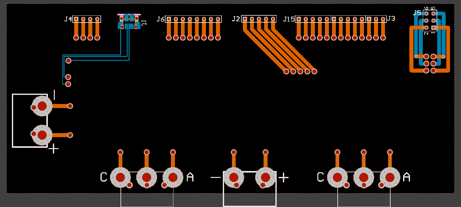
Test board
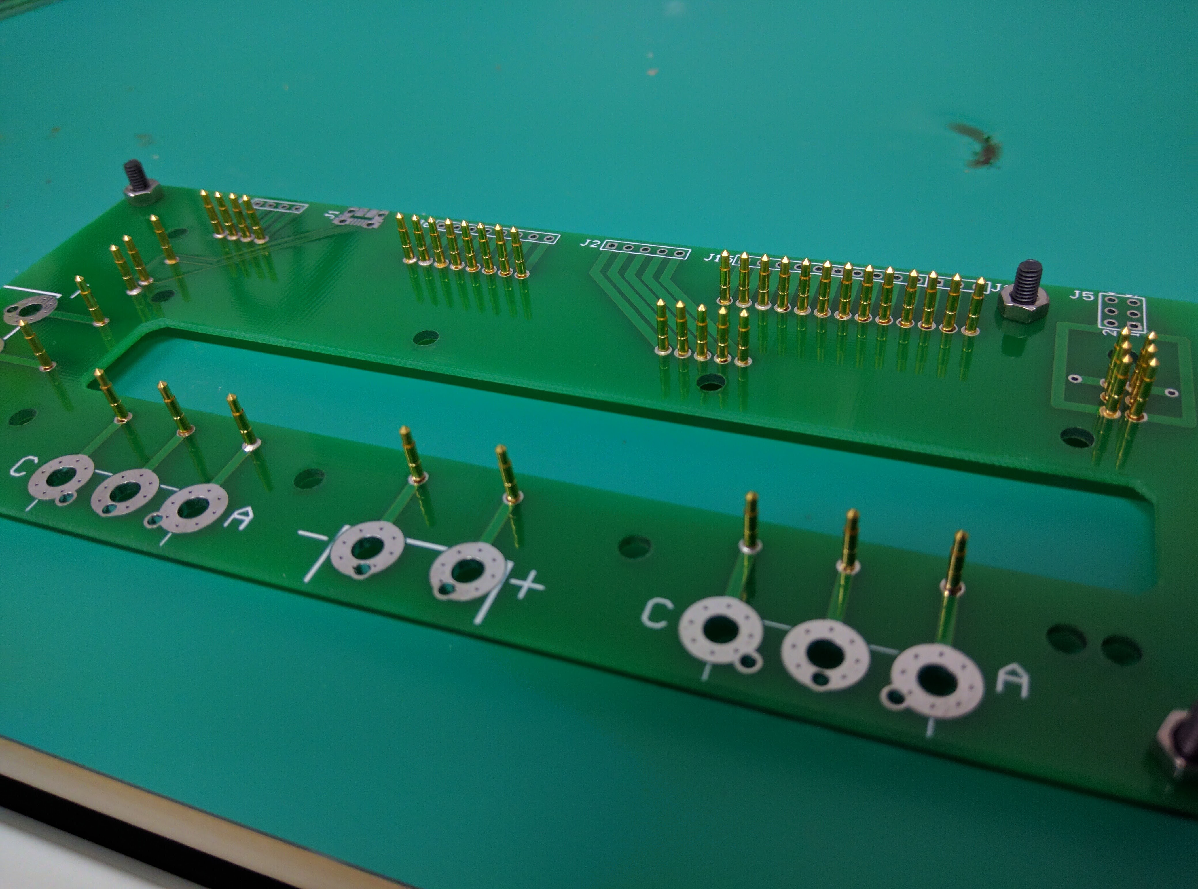
To quickly test the board, one of the best ways is to make a bed-of-nails that can make connection to all the required places on the board for testing all in one go. The idea is to use spring-loaded pins like these pogo pins that sit on a separate PCB underneath that can break out the connections to the test equipment. @Thomas Branch made one on Circuit Maker here. At the time of writing the design is not completely finished reviewing yet, but should be done soon.
Here are some picutres:
![]()
![]()
![]()
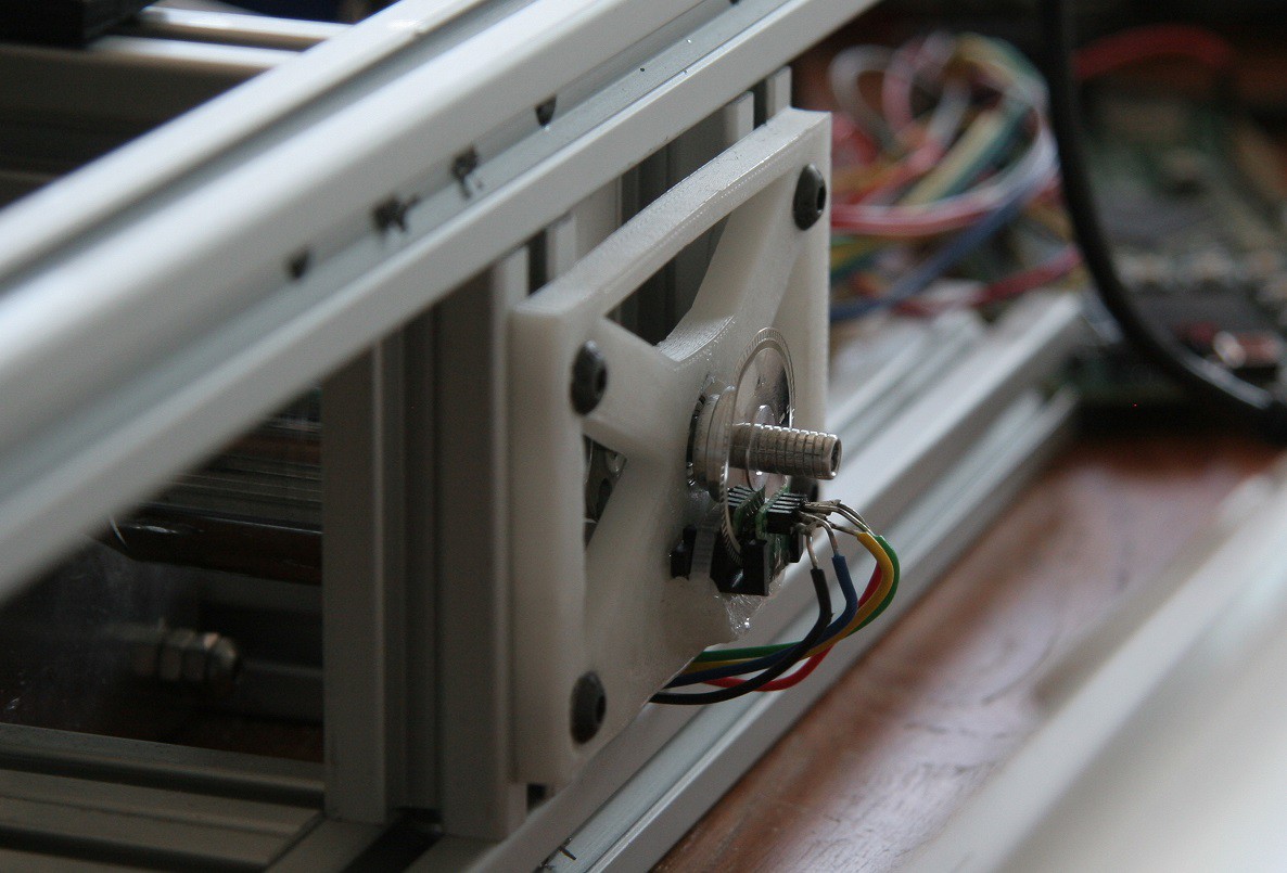
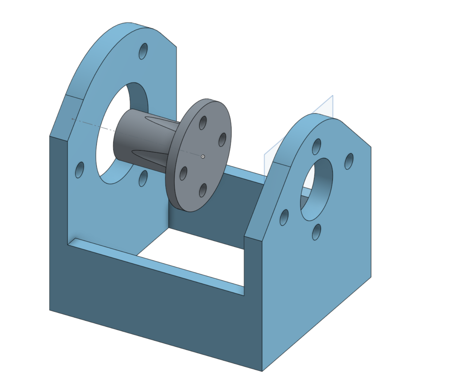
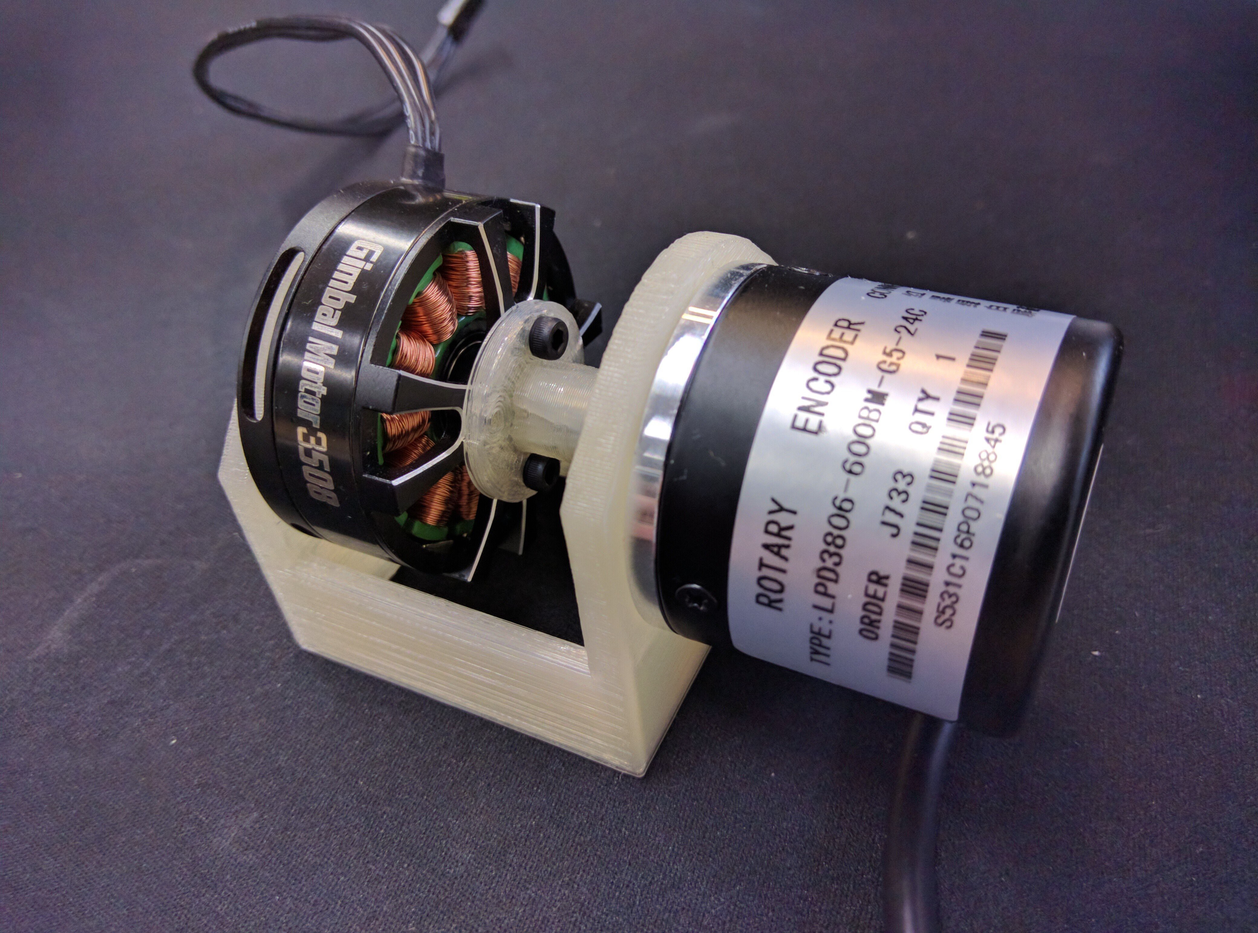
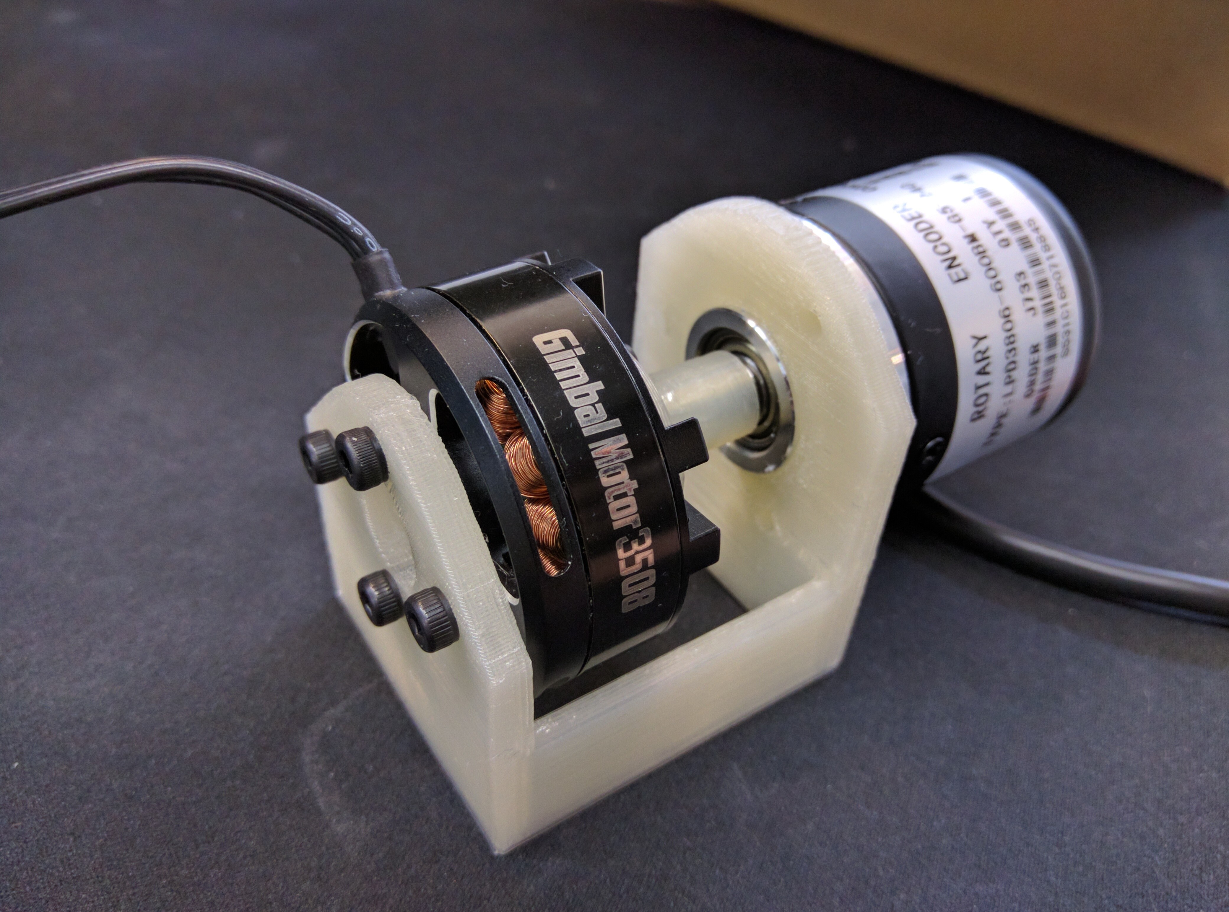
Encoder - motor rig
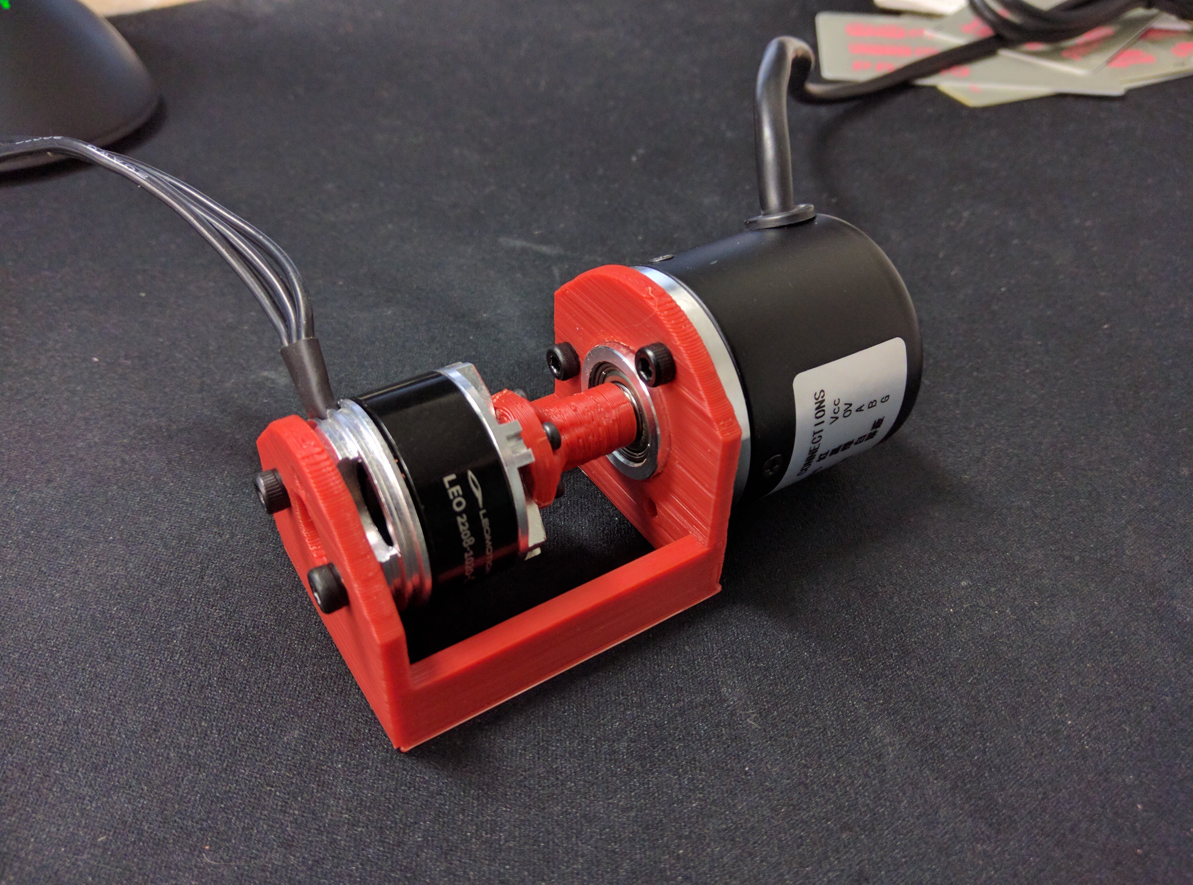
To do the aforementioned motor tests, we need a motor and an encoder for each channel. The setup is designed to be as simple as possible, so it is just a motor directly coupled to an encoder, nothing else. I picked this gimbal motor since I just happened to have it lying around. But I picked a gimbal motor in particular since its high phase resistance means that if there are any bugs that cause the voltage to be switched on much higher than intended, it means that it doesn't just blow up immediatly, just melts slowly (;
I picked this encoder. You can find the design on onshape. Below are some pictures:
![]()
![]()
![]()
-
Testing: Progress update
11/26/2016 at 15:28 • 1 commentI mentioned in a Previous post that before we can start manufacture, we need to have some basic functionality tests to preform QA testing. For a couple of months I was unable to work on this project, but now I am back to being able to spend most of my weekends again. So I have been able to make some progress.
Currently the following is ready:
- Testing rig with a motor and encoder
- Testing PCB with pogo pins to make quick connections during testing
- Low level code to trigger current sensing and motor control from the 3-phase PWM pheriperal
- Online current sensor calibration
- Lock-in, open-loop voltage vector motor spinning
- Automatic motor resistance measurement
The following is still left to be done before manufacturing can commence:
- Test that the bed-of-nails board makes good electrical contact
- Check that the transient response of the current sensing is good
- Low level code to allow hand-over of the ADCs between the two motor channels
- Write the encoder drivers
- Finish up the test routines to be able to detect faults
Pictures and video!
Below is a motor-encoder pair doing lock-in, open-loop voltage vector motor spinning.
New motor test cradle. The design is openly available, Link.
![]()
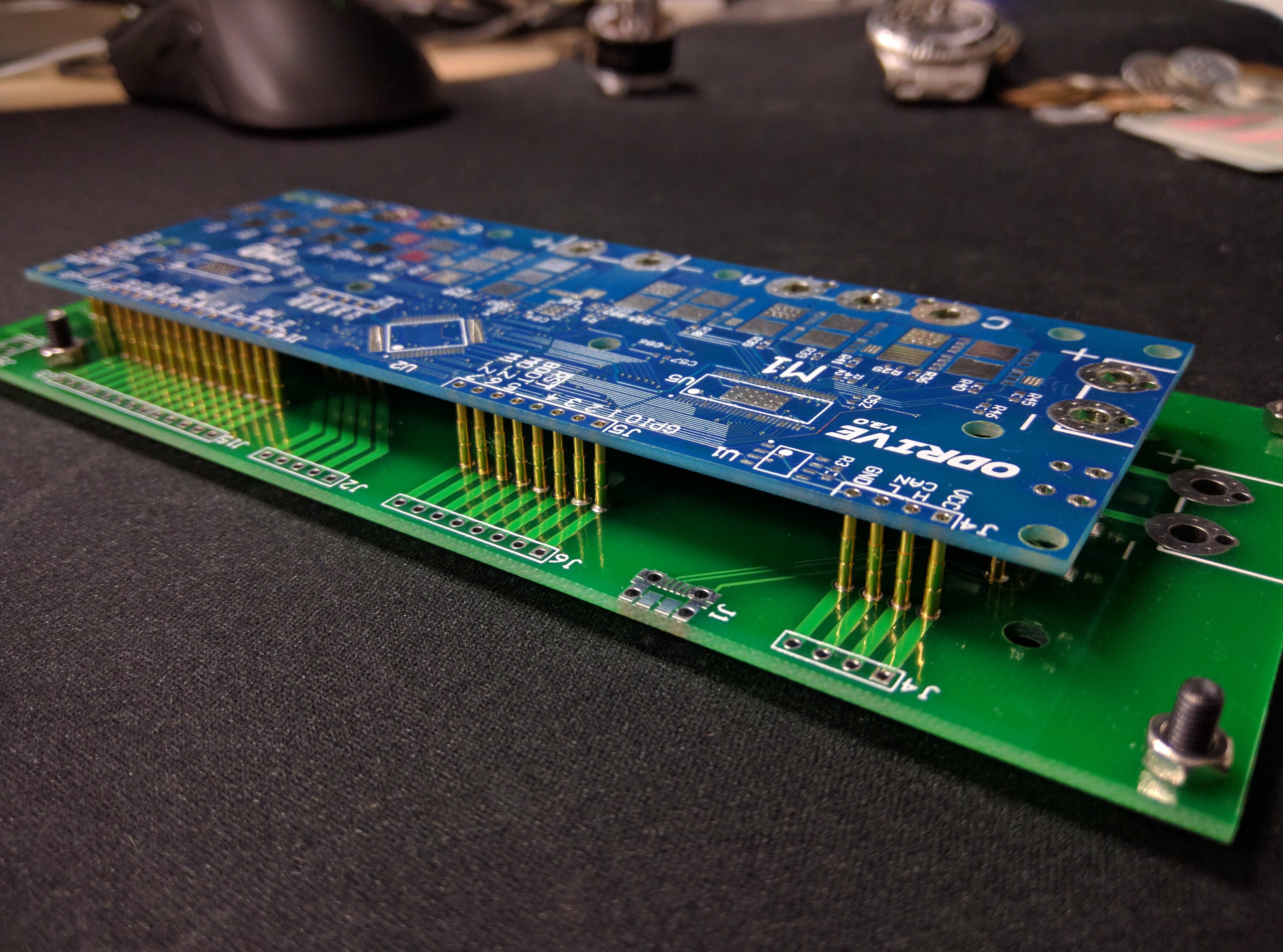
Some pictures of the bed-of-nails. The design is openly available, Link.
![]()
![]()
-
Prototype manufacturing run!
12/03/2016 at 09:51 • 9 comments![]()
The time has finally come for the manufacturing run of ODrive v3.1. They are now on the way, and should arrive early to mid January.
At this stage, around 20 board kits are going out the people who signed up to the "Inital development" phase.
Since the boars are going out to just a small group of early developers, I will have the time to personally get you up to speed with the codebase and help to get going with the hardware. Then, together, we can prepare some stuff that is a bit more stable and a bit more documented for when the alpha testing begins.
The cost for me to get this small batch of boards manufactured was $96 per board, so that is the amount I need to ask for a kit, plus shipping.
The kit involves basically everything seen in the above picture, and consists of:
- ODrive v3.1
- USB Programmer
- A set of the optional large gauge wire screw terminals
- A set of pin headers
- Some nylon standoffs
I hope that ODrive will be able to help you make an awesome robotics project, thank you so much for your contribution to helping people have access to open robotics hardware and software.
-
Two motor operation
12/14/2016 at 18:37 • 0 commentsTwo motor operation is finally done. For those of you who are interested, here is the interrupt-dance that makes it all work: Link.
Cheers!
-
Sexy machine assembly
12/24/2016 at 04:13 • 1 commentIn my previous post I mentioned that the first batch of ODrive v3 is being assembled. I asked CircuitHub to take a video. And holy shit, industrial pick and place machines are so sexy! Hopefully ODrive will enable inexpensive machines that go this fast ;D
![]()
![]()
-
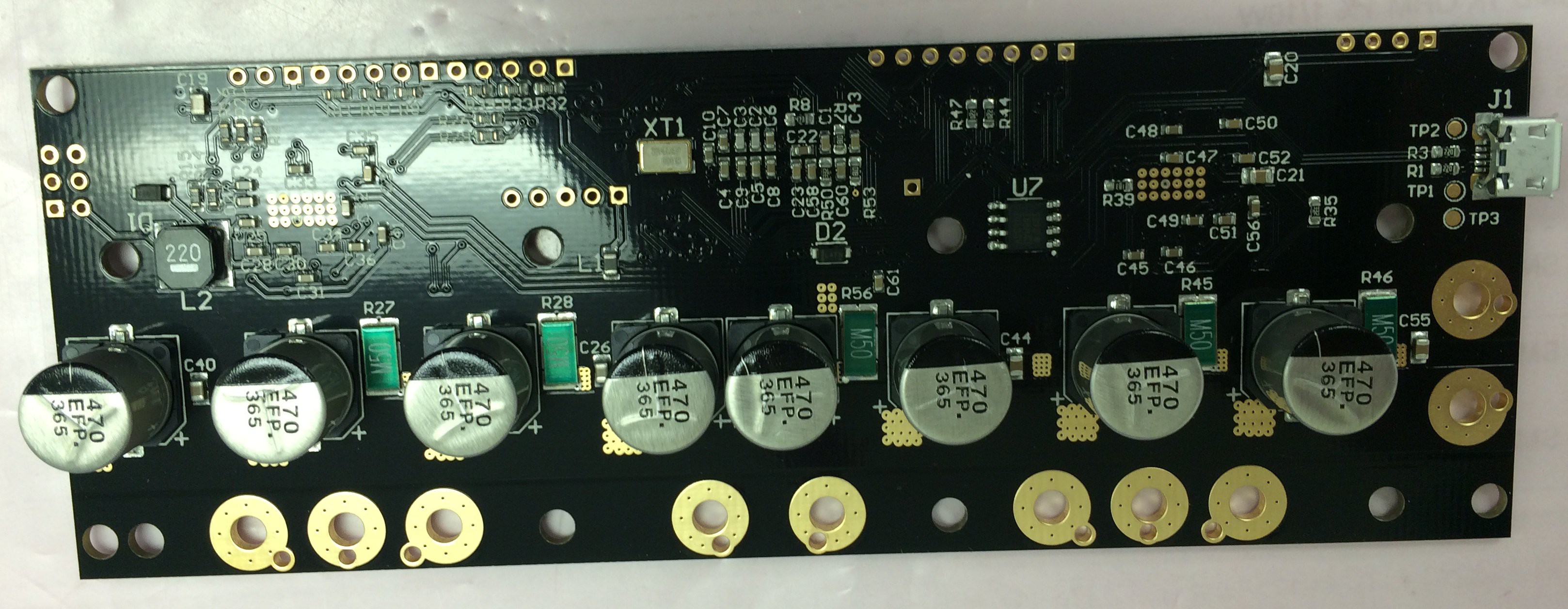
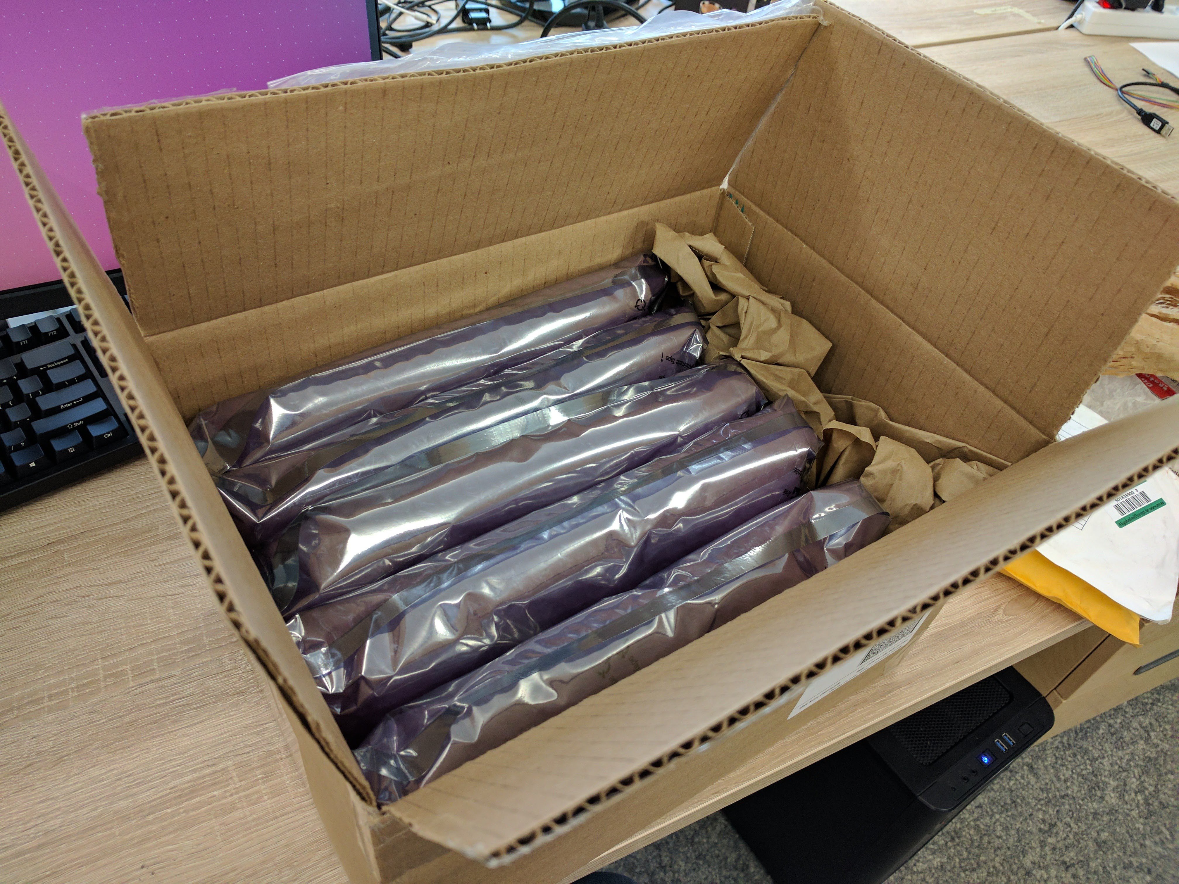
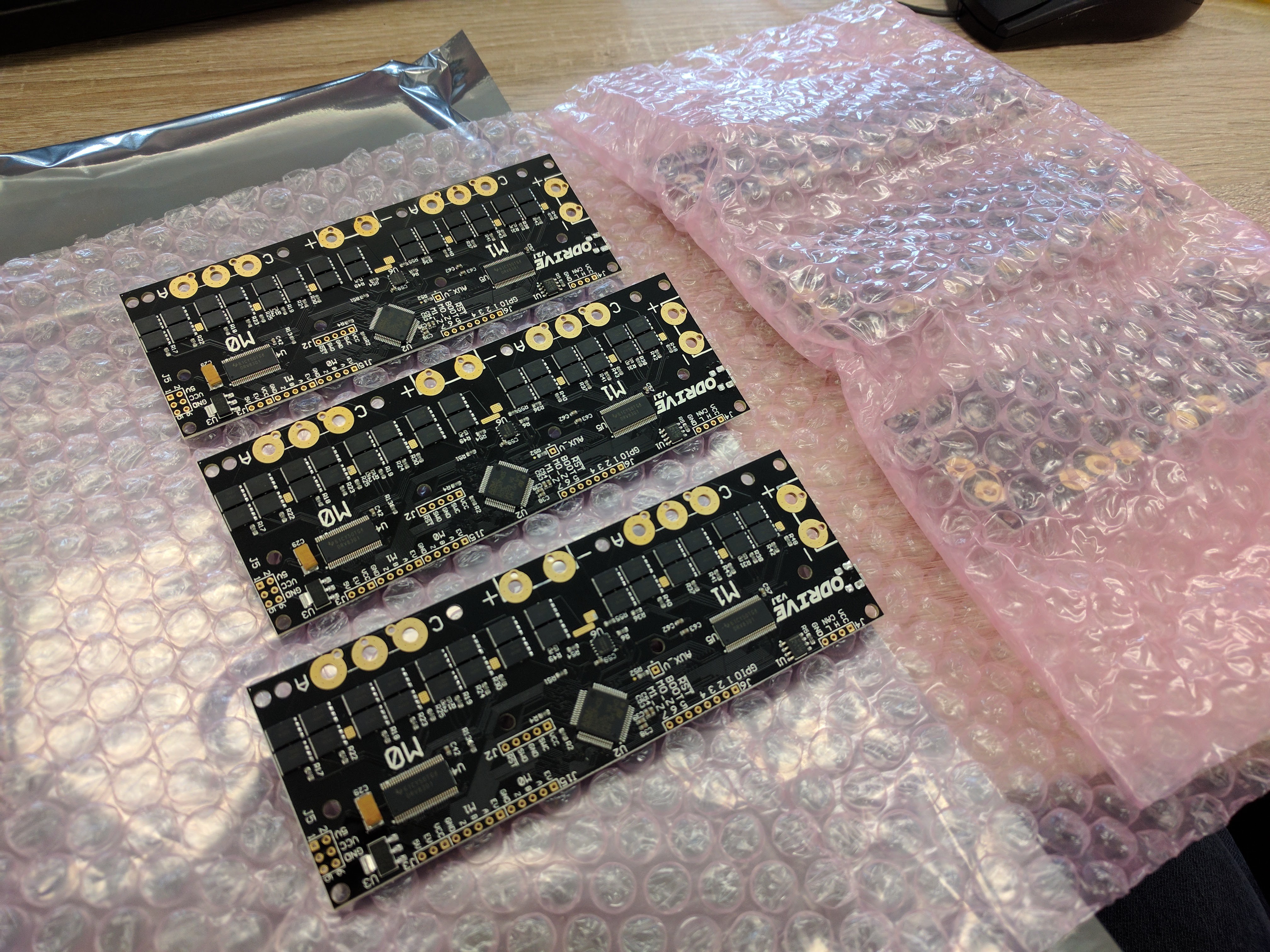
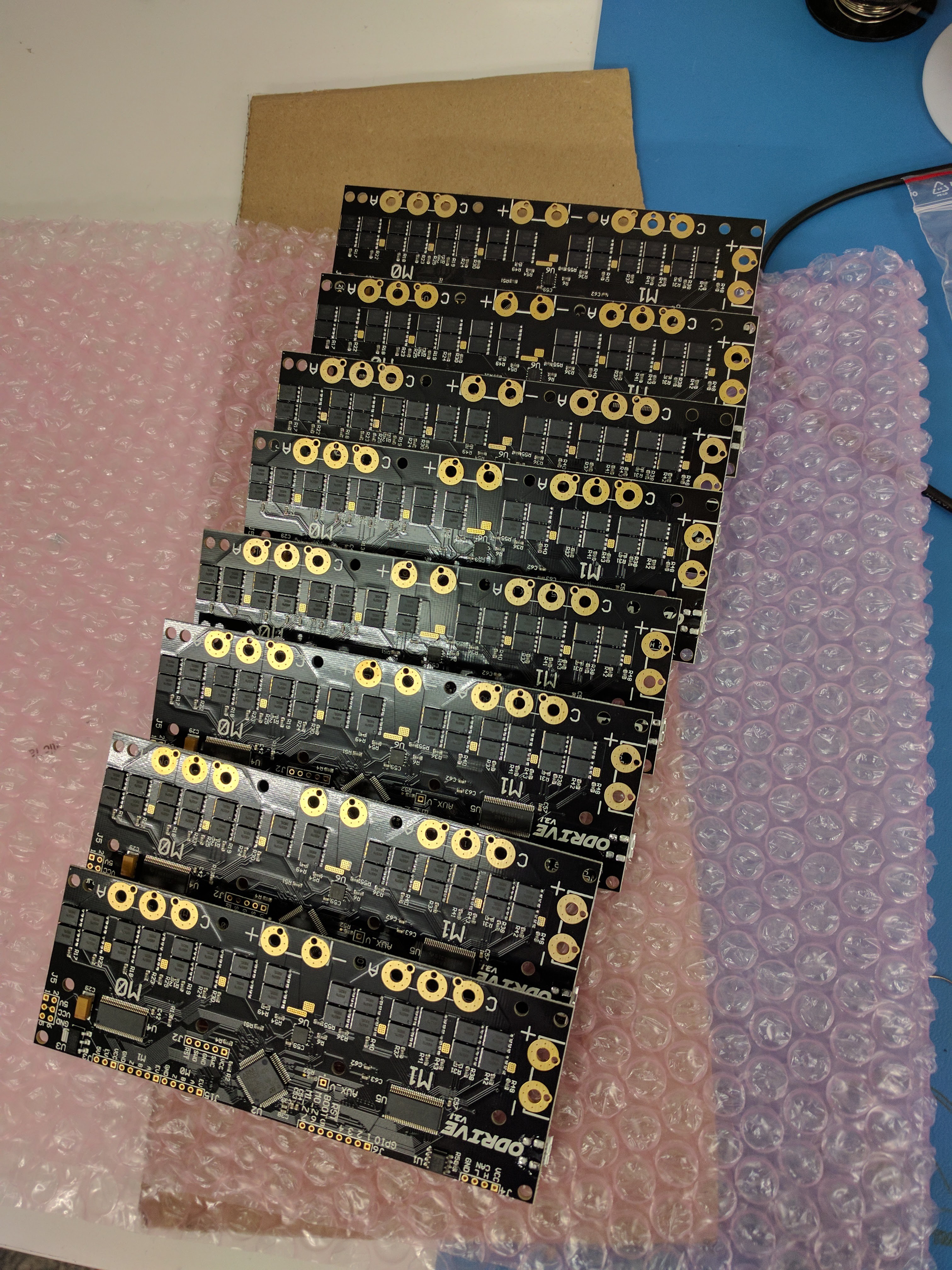
The Boards Have Arrived!
01/20/2017 at 17:39 • 4 commentsCheck this out, a box full of goodies:
![]()
Inside each of the 5 packets, are 6 ODrive v3.1. And they are in lovely black and gold. The manufacturing quality of CircuitHub is really top notch ;D
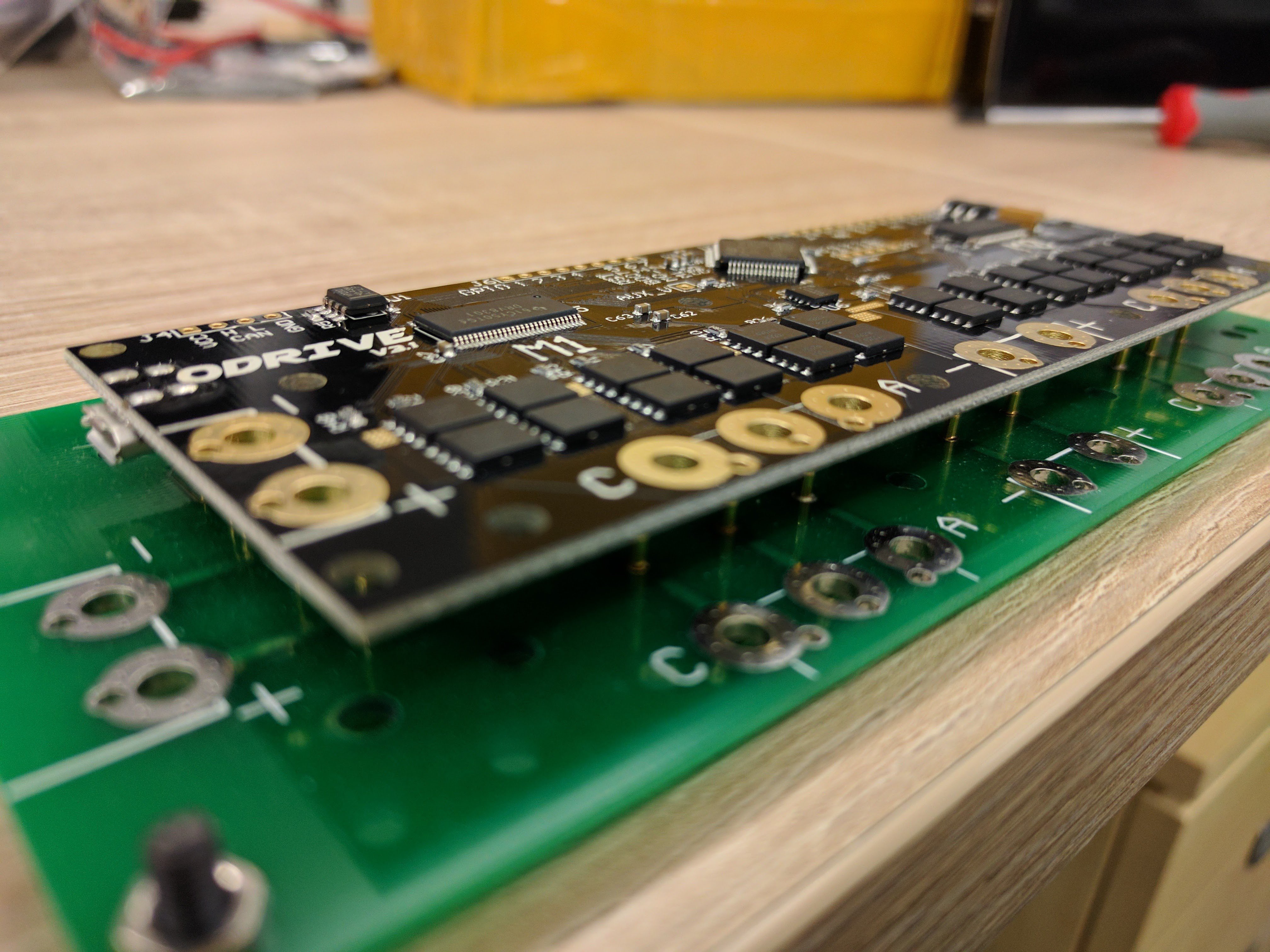
![]()
Here is a picture of the new boards on the testbed. Actually I never used the test bed in the end, since the manufacturing quality was so good. I don't expect any defects, and with such a small batch I don't mind replacing a board if it was indeed a DoA.
![]()
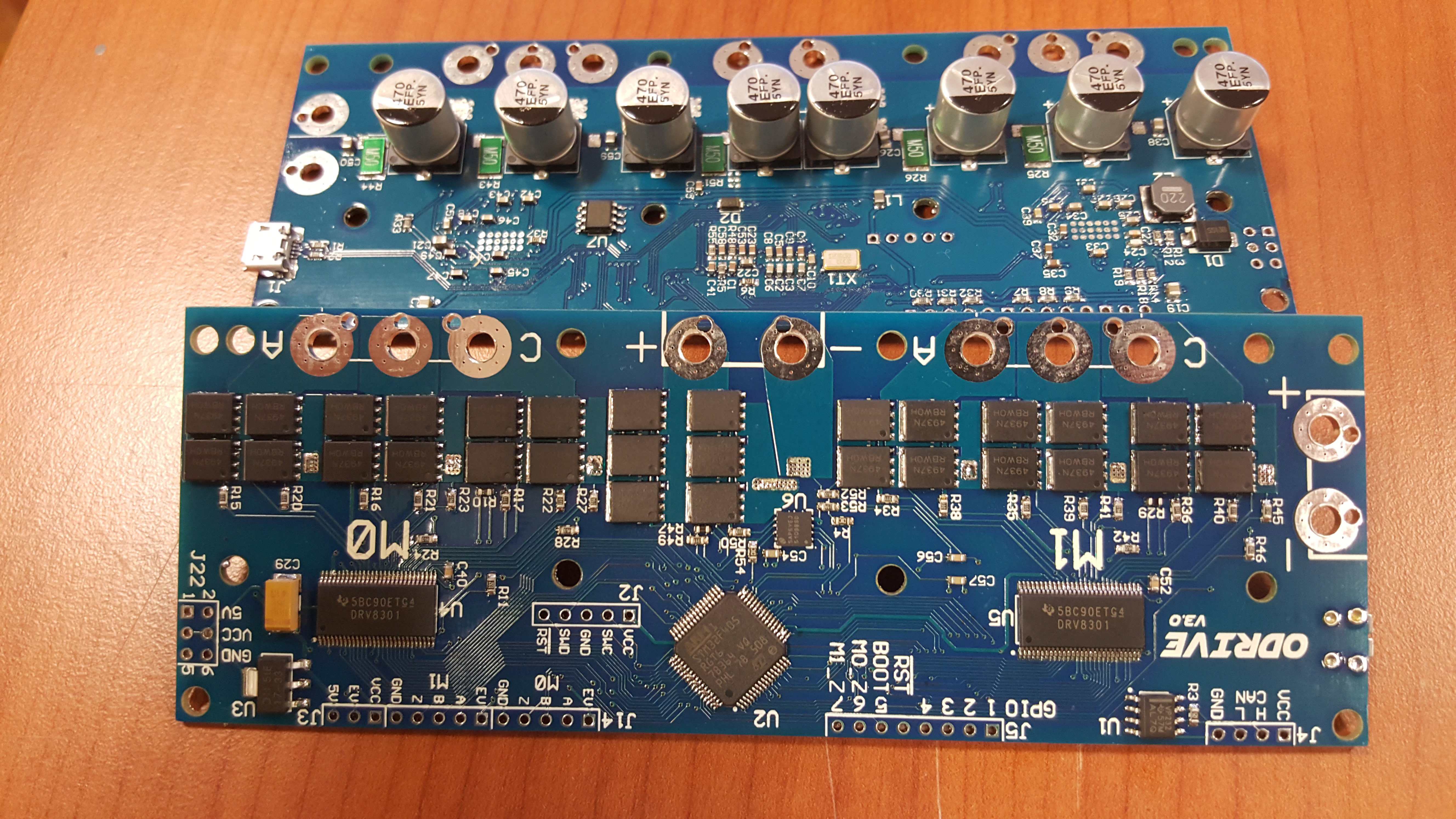
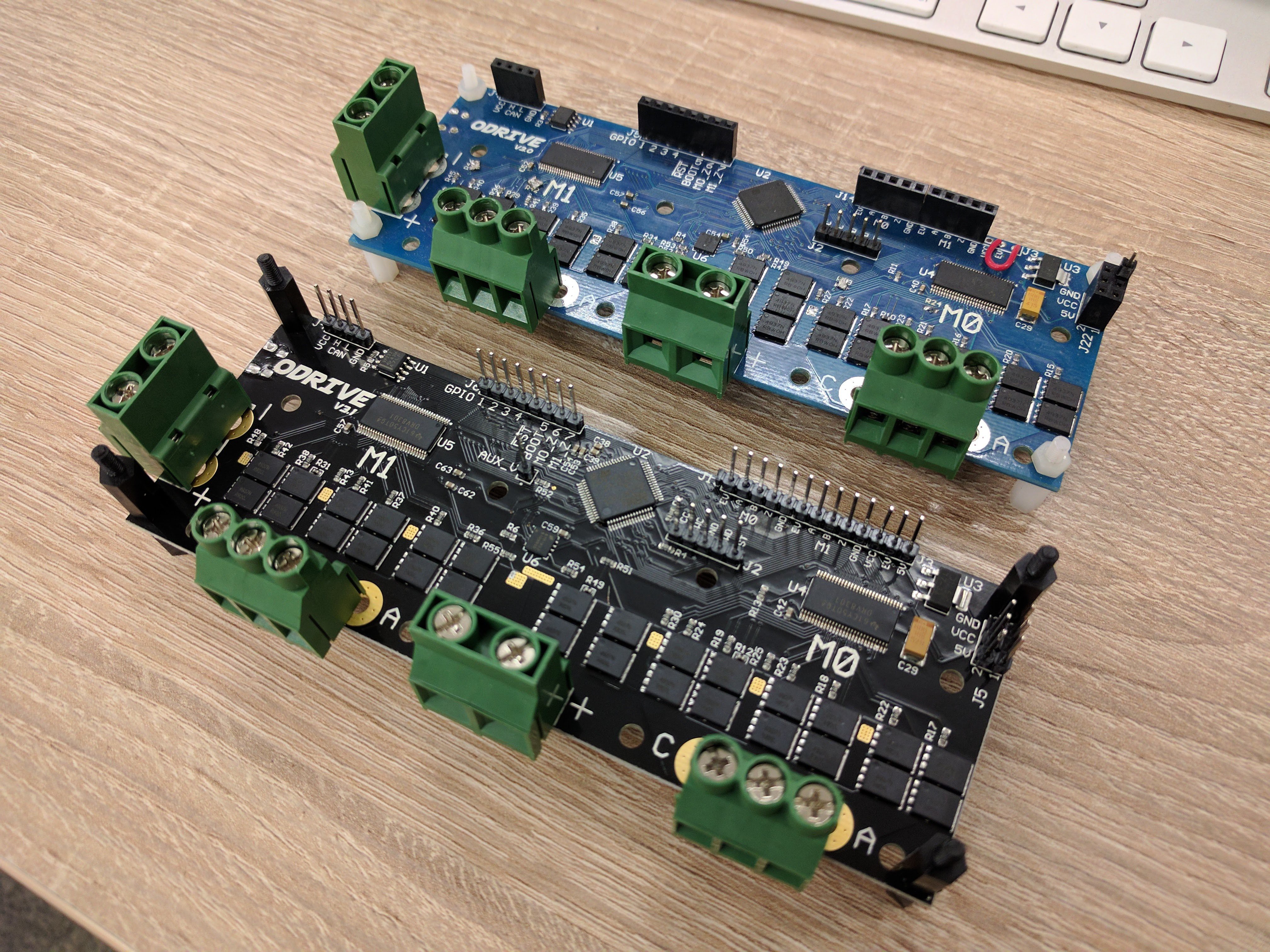
ODrive v3.0 next to v3.1. Black looks great ;D
![]()
Preparing some kits to go out with the first round of pre-alpha board orders.
![]()
With the help of the early developers who will be helping, hopefully Alpha release will occur soon. If you want to get notified when that happens, make sure to sign up for the board manufacturing run: Link.
-
Progress Update
03/10/2017 at 01:48 • 6 commentsIt's time for an update.
There has been some significant progress on the software including two major new features. The v3.1 hardware that I wrote about in the previous post has been further tested, this time not only by myself, but by several early developers. We managed to find only one serious hardware bug so far, which is fixed by replacing four capacitors. With the fixes to those bugs, the alpha testing stage is around the corner.
New Features
Two new major features are ready: USB Serial and brake resistor control.
USB CDC - The main way for the ODrive to communicate with a PC or embedded computer (such as the RaspberryPI) is via USB Serial (aka USB CDC). This interface will be used both for sending configuration and commissioning commands, and interfacing with existing tools that have G-Code style output. With further extension, it can also support binary, and various application specific, protocols. Yay for open source.![]()
With significant help and contribution from @nickaknudson we now have a working USB CDC interface, which runs in a task parallel to the motor control tasks. The current implementation is very basic, it parses the commands and relays position commands directly to the motor control task. Going forward we will add trajectory generation to support coherent movement between multiple axes. Then we can handle the basic G0 and G1 G-Code "go-to" commands.![]()
Brake resistor - Software support for a brake resistor is now in place. This means that we can safely dissipate the energy absorbed when decelerating. This is important since many power supplies cannot handle reverse energy flow. The implementation has the two motor controllers estimate their power draw, and then calculates the net power draw from the power rail. If it is negative in total, the pulse width of the brake resistor control is set to exactly dissipate and hence cancel this power.
Demo - In the above video you can see a demo of both features.
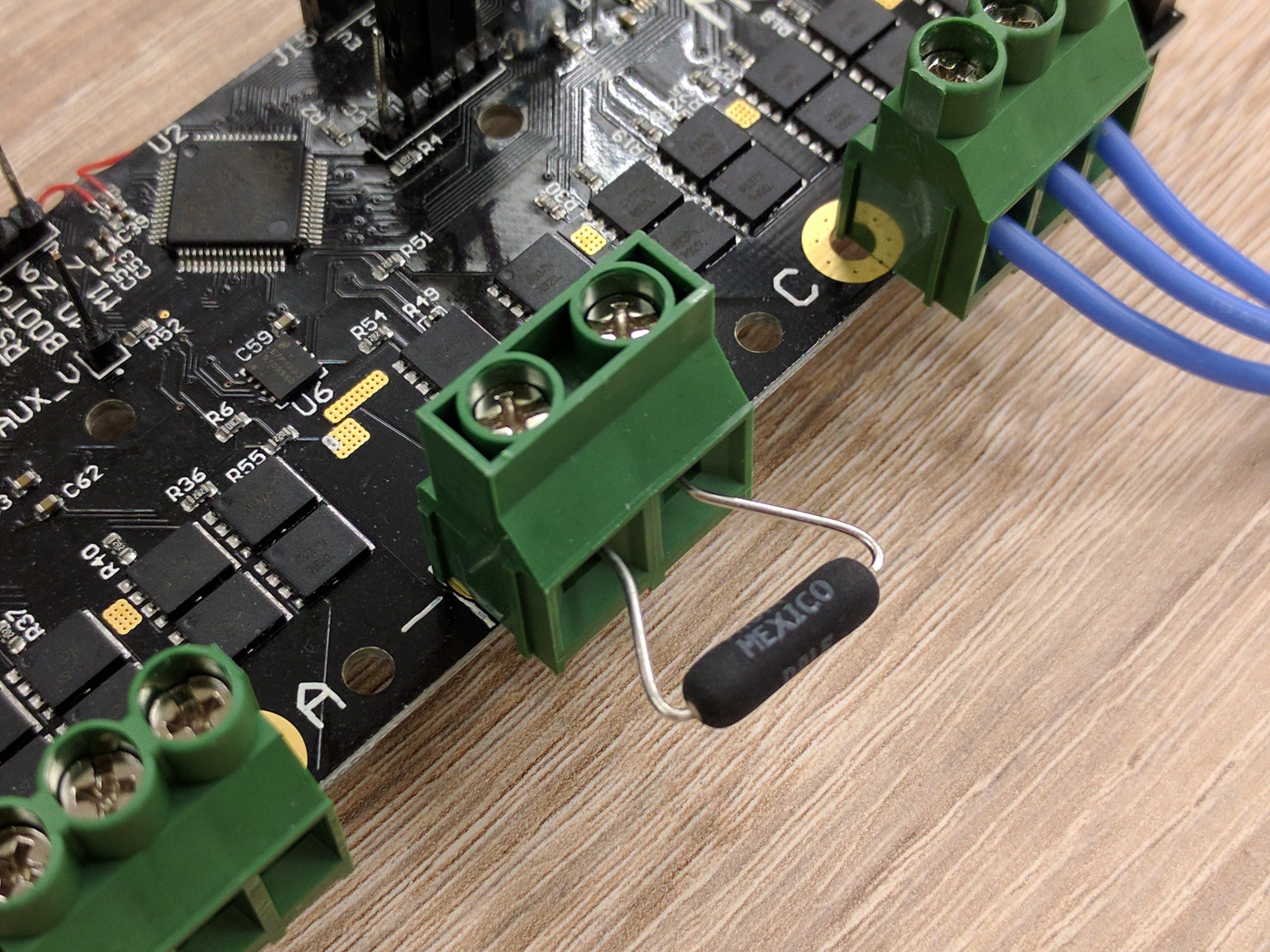
Hardware bug found
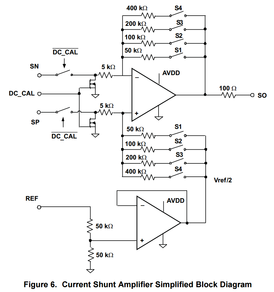
Everyone knows that voltage amplifiers have high input impedance, and low output impedance. Right? Well, apparently not.
![]()
Above is a figure from the DRV8301 datasheet. 100 ohm output impedance doesn't qualify as low output impedance in my book... So this extra output impedance is causing a way too large "R" in the RC filter that filters the current sensor output. Hence the current sensing is way too slow, and barely usable.
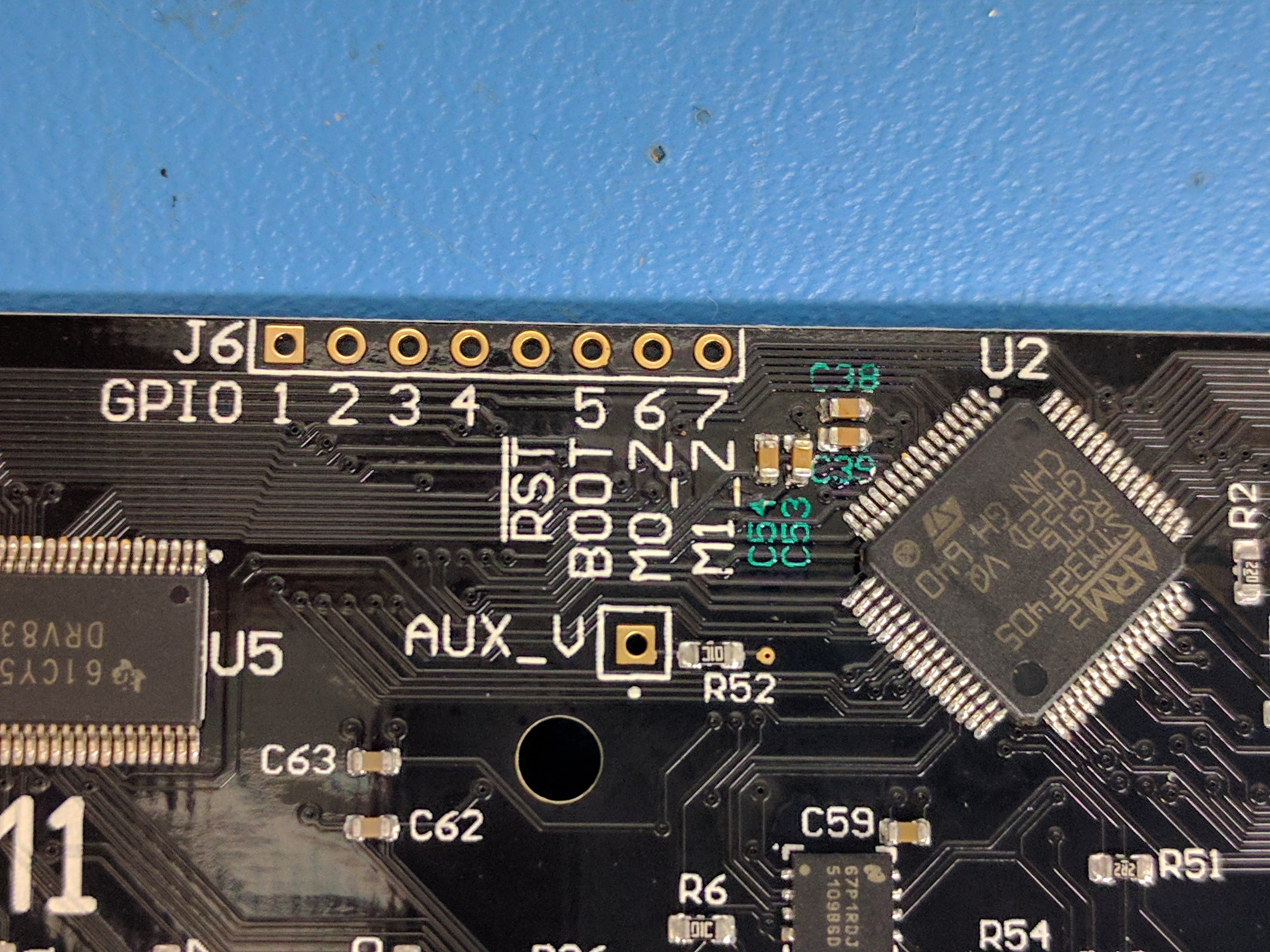
![]()
The fix involves replacing the capacitors highlighted in green painted labels with 2.2nF capacitors.
![]()
Replacing 0603 capacitors on lots of boards gets quite tedious. Nevertheless, I don't want to ship out any of the remaining ODrive 3.1 boards with known errors on them. As you can see, I have 8 left, and they should all work now. If you are interested in claiming one of them, sign up for an Initial Development board on this form.
Crowdsourced Testing
I'm incredibly grateful for the people who were brave enough to pay for a board that was completely untested and with missing core features, and generous to spend their time helping to test those features as the were being brought up. You know who you are: Thank you!
Below are some videos of some ODrives out there ;D
ODrive v3.2 and Alpha Testing![]()
Already almost 200 of you have signed up for a board and at the same time shared with me the amazingly diverse projects that you want to use ODrive for. There were many projects that I expected like 3D printers, CNC mills, and Pick and Place machines. However there were so many cool and diverse projects I didn't expect. Here are some examples that was mentioned by more than one person each:
- polargraphs
- robot arms
- walking robots
- exosuits
- motion simulation platform
- heavy duty camera gimbals
- camera dolly/slide
- under water robots
- mobile ground robots
- various art projects
I aim to have a quote ready for the manufacture of ODrive v3.2 at the beginning of April, and with that, I will open pre-orders for the Alpha release. I will send an email to everyone signed up on the google form. It will also be possible for anyone else who wants to join in during the couple of weeks that the pre-order is open, before manufacturing starts.
Full Throttle
The project is gaining momentum. With the fantastic response from the community, I am motivated to spend more time on this. In April, I will quit my current job, and I will be able to work on ODrive full time. This should lead to approximately a factor 8 increase in my contribution rate.
Lets do this!
ODrive - High performance motor control
Hobby brushless motors are incredibly cheap and powerful. However we need a way to make robots out of them. ODrive is that way.