 w_k_fay
Atmega8 based inductance meter:
The LM393 comparator functions as an oscillator. The output is around 600khz without an inductor in the test socket. Placing an inductor in the test socket changes the frequency of the oscillator. The microprocessor calculates the inductance based on the change in frequency. The measured oscillator frequency and the calculated inductance are displayed on the LCD.
It is easy to replace the LM393 with a LM311 if you wish to do so. Just short pin 5 BALANCE to pin 6 BALANCE , and transpose the inputs, and the output. I did not have any LM311's so I used the LM393 dual compatator. You should ground the unused inputs on comparator B to prevent unwanted oscillations in the circuit. I ended up using the LM393 because my stash of LM311's were faulty, however either will work fine, A LM339 will also work if that is all you have on hand.
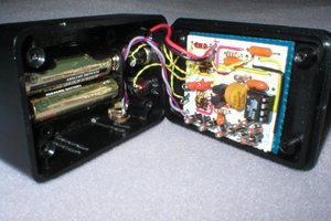
The button on the front is used to calibrate the circuit. Pressing the button closes the relay to ground and calibrated your circuit with L1. It then replaces the set startup values it the firmware.
You may find that you need to play with the value of C11 to obtain accurate results. I added 50pf in parallel with C11 to get good results. Having an accurate inductor would also be helpful for setup.
The original firmware included a display hold function. I left this in the firmware and did not bother to add the buttons, as it did not seem to be very useful. If you have extra buttons and like spaghetti wiring go for it.
I chose the Atmega8 over Atmega48, used in the original circuit because I can buy the Atmeg8 for less and the extra 4k of memory will allow for the addition of new features somewhere down the road.
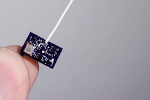
I built the circuit on perf board and I did not make a PCB layout for it. I think it is reasonable to build on perf board, however if anyone wishes to design and publish a PCB for future development that would be nice too.
Fuse settings for the Atmega8 are LOW: CE HIGH: D9 . Fuse settings and other notes can be found in the source.
 Scott
Scott
 Alpenglow Industries
 Sagar 001