Hackaday 2016 Prize Video
Ever hold an object at an angle to the light, to see subtle details in the surface? Now imagine that technique on steroids, and you have Reflectance Transformation Imaging, RTI for short. Photographs are taken of an object at multiple lighting angles with the camera position fixed. These images are then analyzed and combined in a computer to create a virtual lighting model, where you can arbitrarily set the lighting direction to maximize the visible surface details. What's more, because the lighting model is in computerized format, it can be mathematically manipulated and changed to further enhance surface details.
The technique was invented in 2000 by Tom Malzbender of HP Labs, and originally intended for use in more realistic lighting of 3D graphics; it's still used for that purpose under its original name of Polynomial Texture Mapping (PTM). Malzbender quickly realized RTI's applications in imaging subtle variations in surface details, particularly for archaeological artifacts. Since its development, RTI's most famous use has been in helping to decode the Antikythera mechanism, the oldest known computing device. But it's also been used for imaging ancient Middle Eastern writing tablets (e.g. Proto-Elamite, Cuneiform, inscription "squeezes", and Aramaic); ancient coins; ancient manuscripts (links one, two, three, four); and many more. There are also other non-archaeological applications, such as forensics and paleontology. For more information on the technique and its applications, visit the website of the non-profit Cultural Heritage Imaging, where you'll also find links to free information and software to aid in the creation of processed RTI data files. A search for RTI on YouTube will bring up many videos on the technique and its applications.
My original interest in RTI was for use in imaging and analyzing prehistoric lithic artifacts, stone tools like arrowheads and dart points. It is often very difficult to photograph these in a way that shows the obvious details of their manufacture. So difficult, in fact, that it's standard practice to use line drawings instead of photographs. I presented a talk on using RTI for imaging lithic artifacts at the 2015 Society For American Archaeology, and I've put up an extended version of that talk along with associated data files at this website. Just to quickly show what the technique can do, the images below are of a Clovis spearpoint found in Arizona, dating back about 13,500 years. The first image is a regular photograph, and little to no detail of the spearpoint's surface features can be seen. The second image was generated using RTI (plus some extra Photoshop processing), and the surface details are now dramatically clearer.
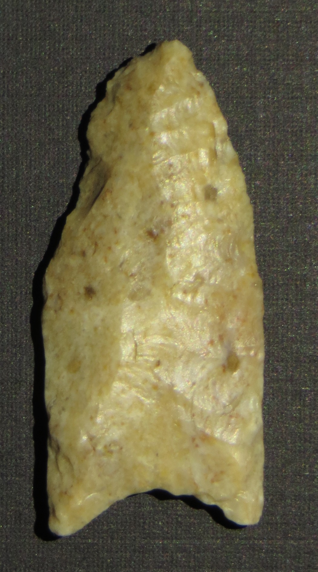 Clovis point: original photo
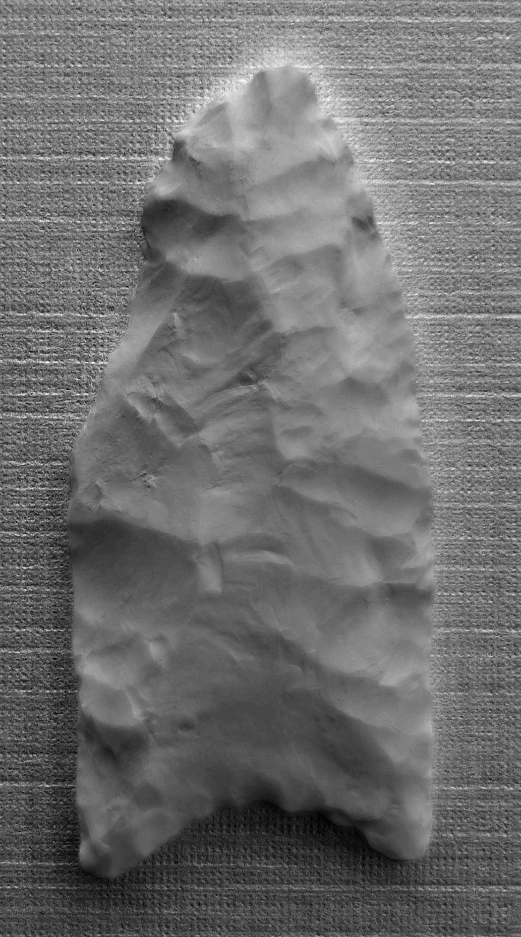
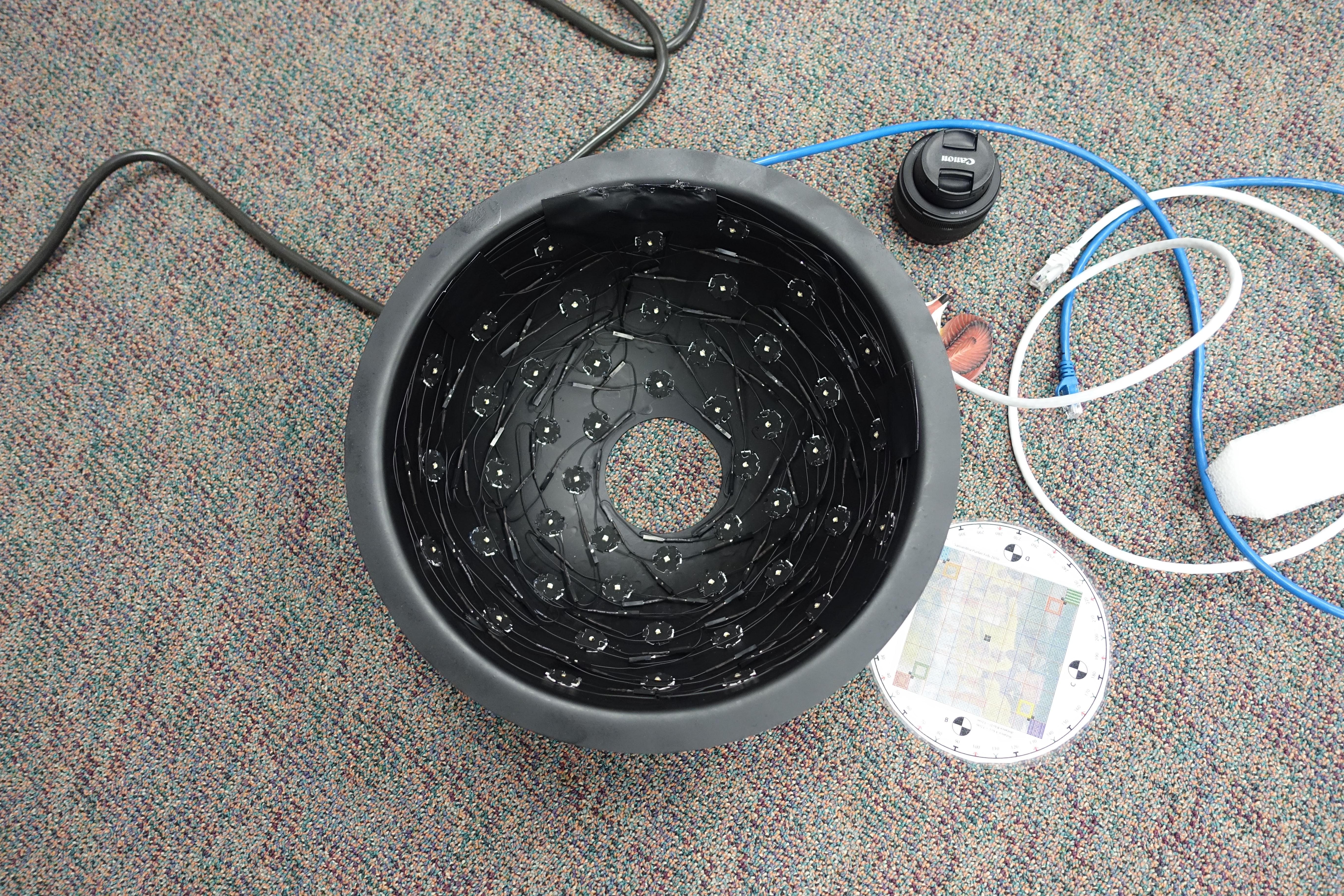
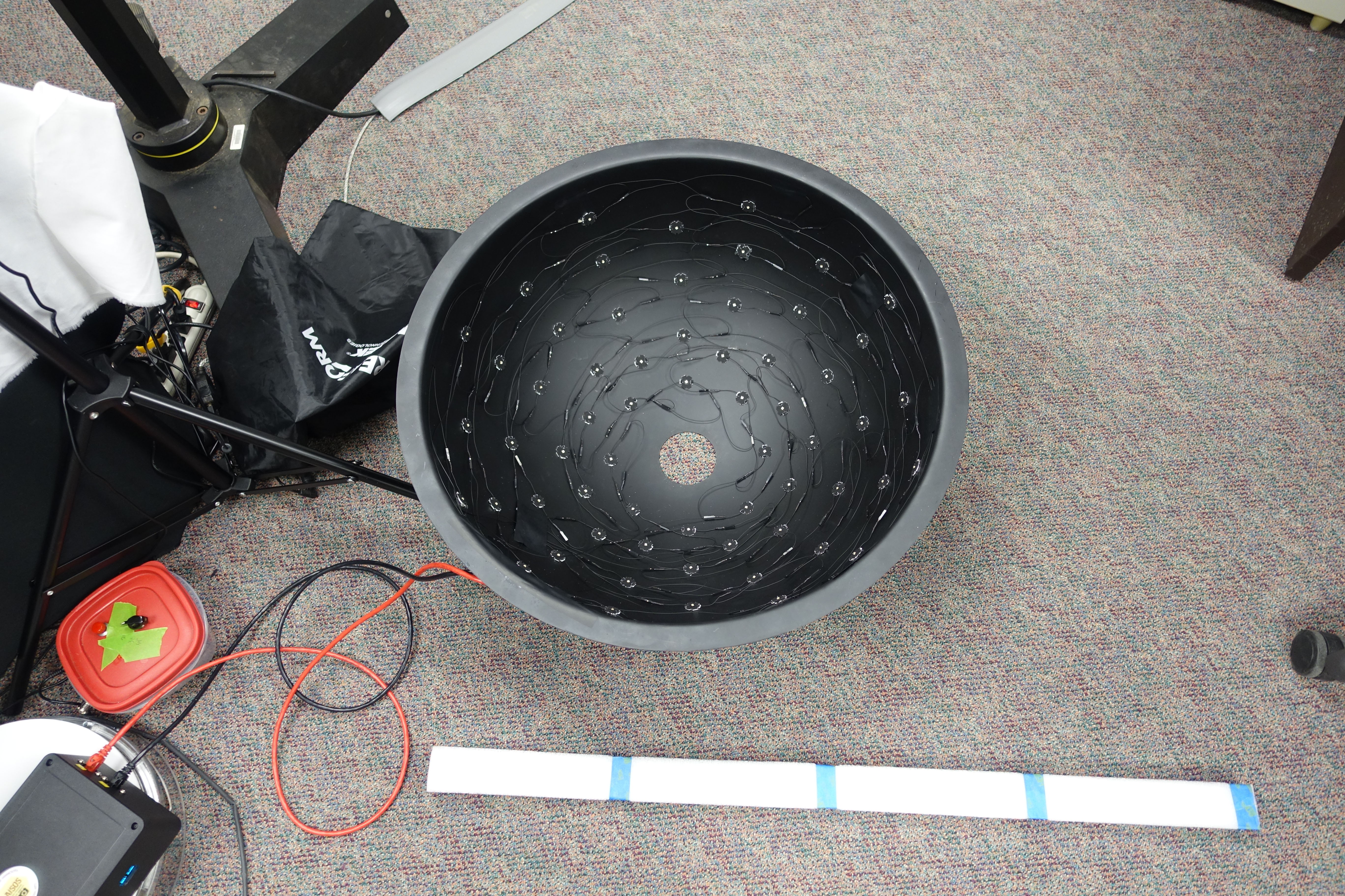
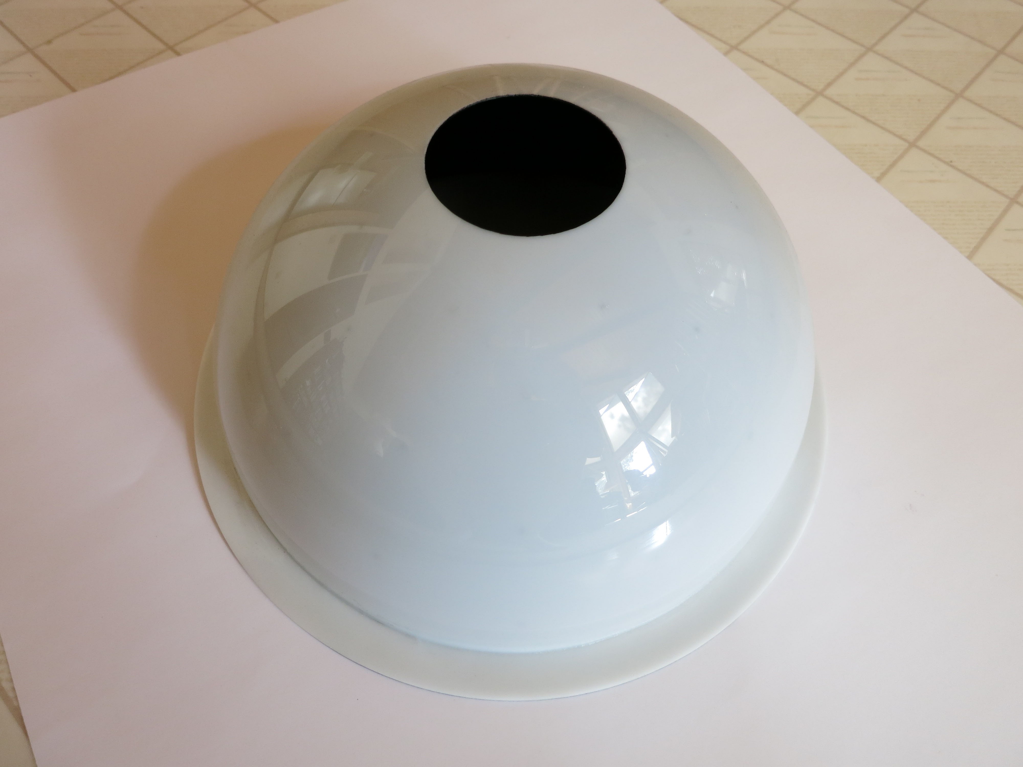
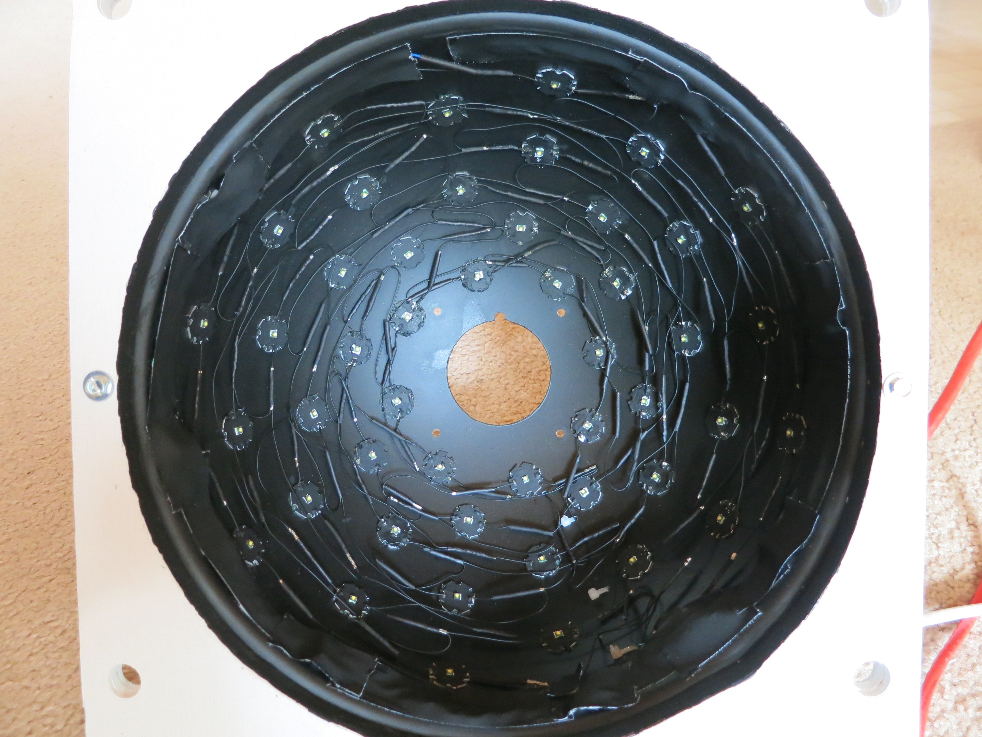
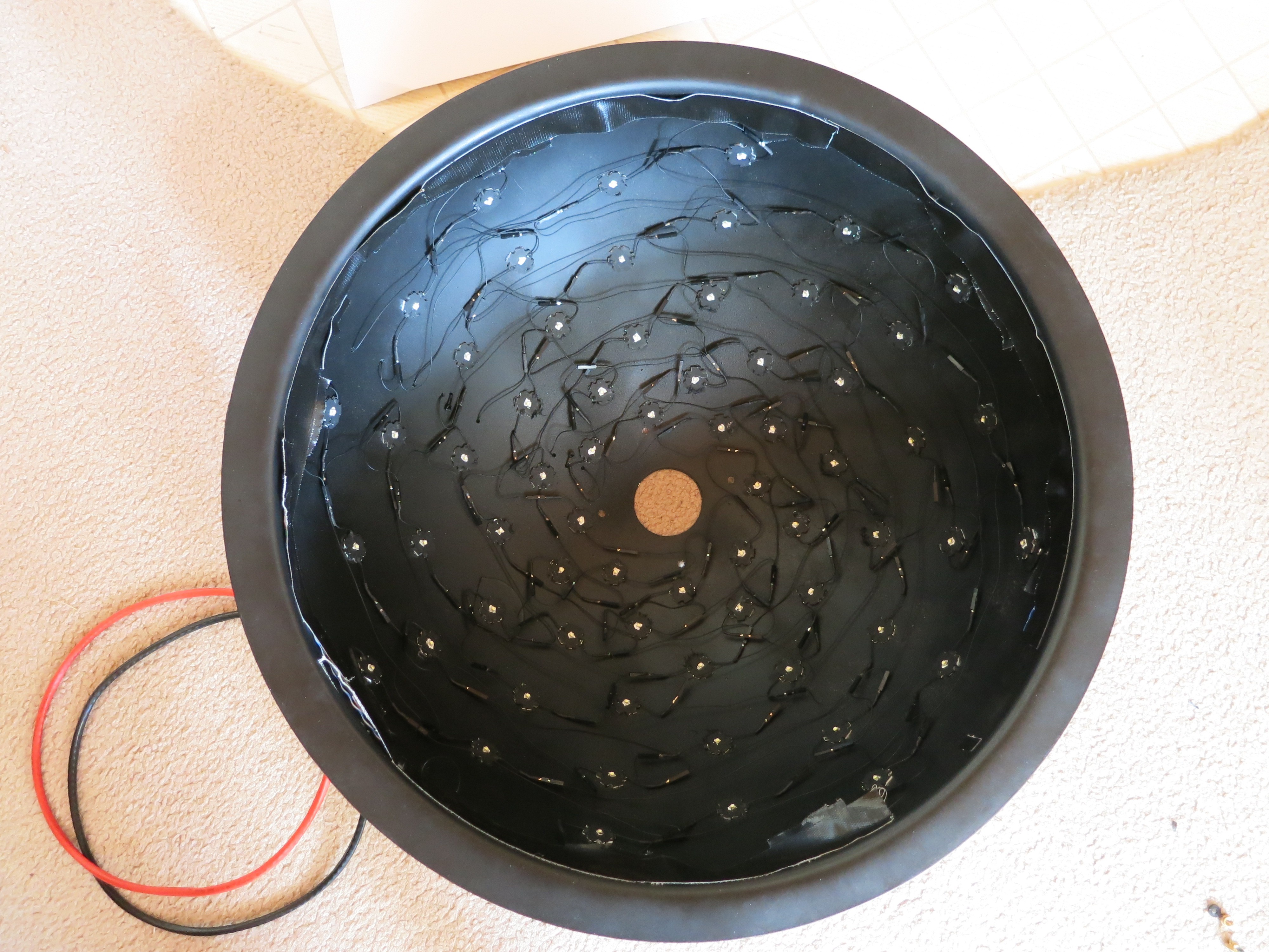
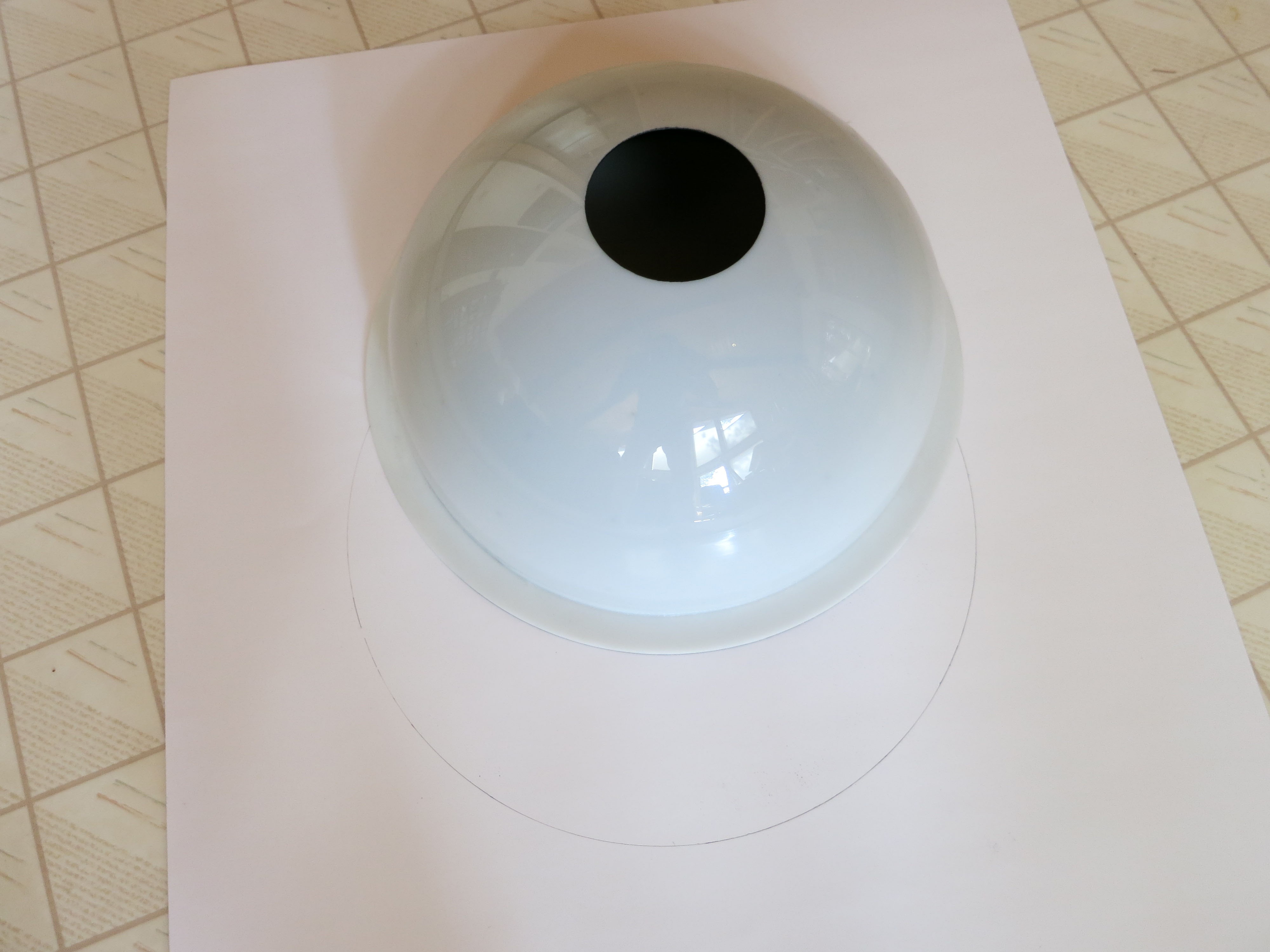
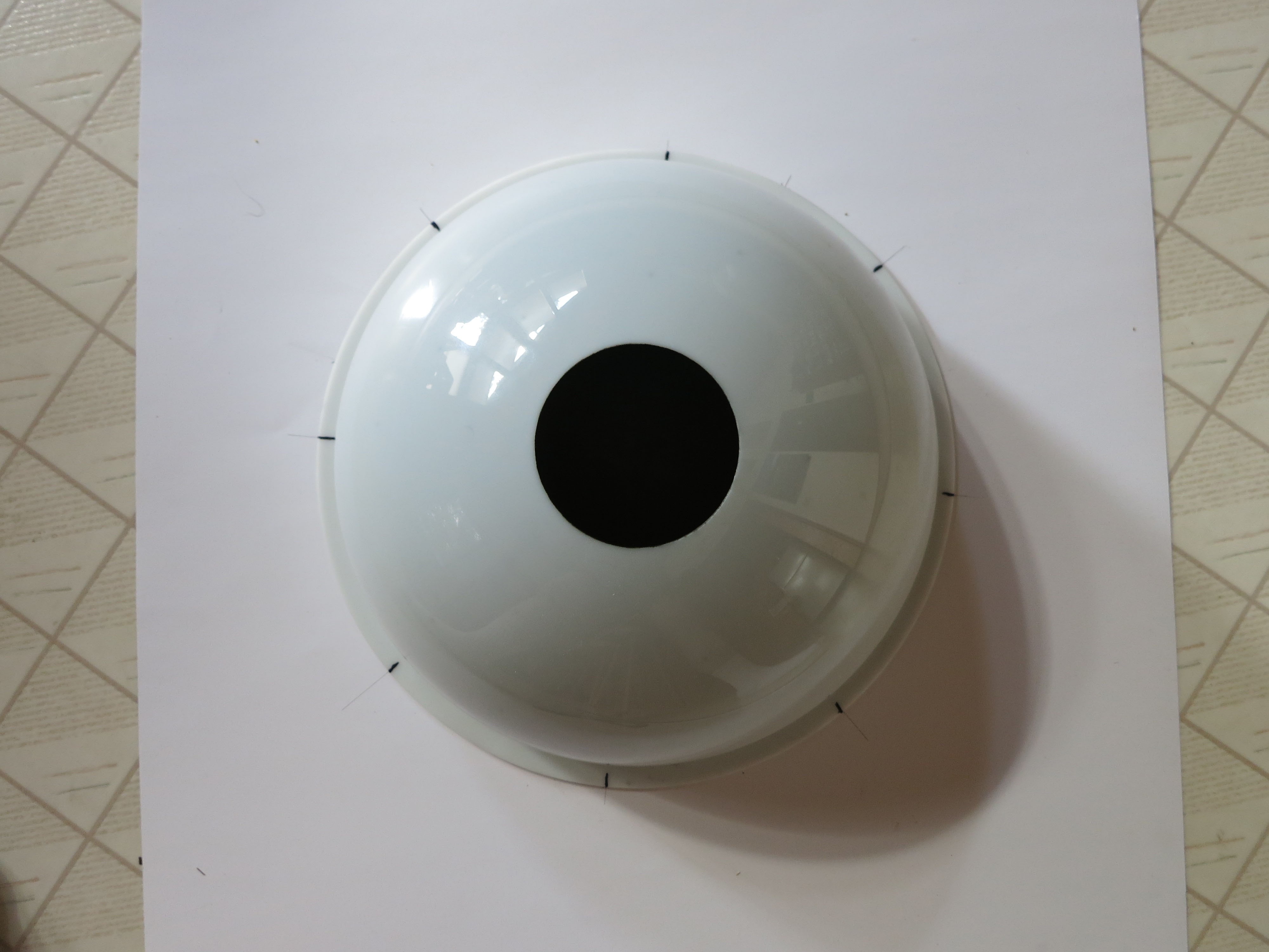
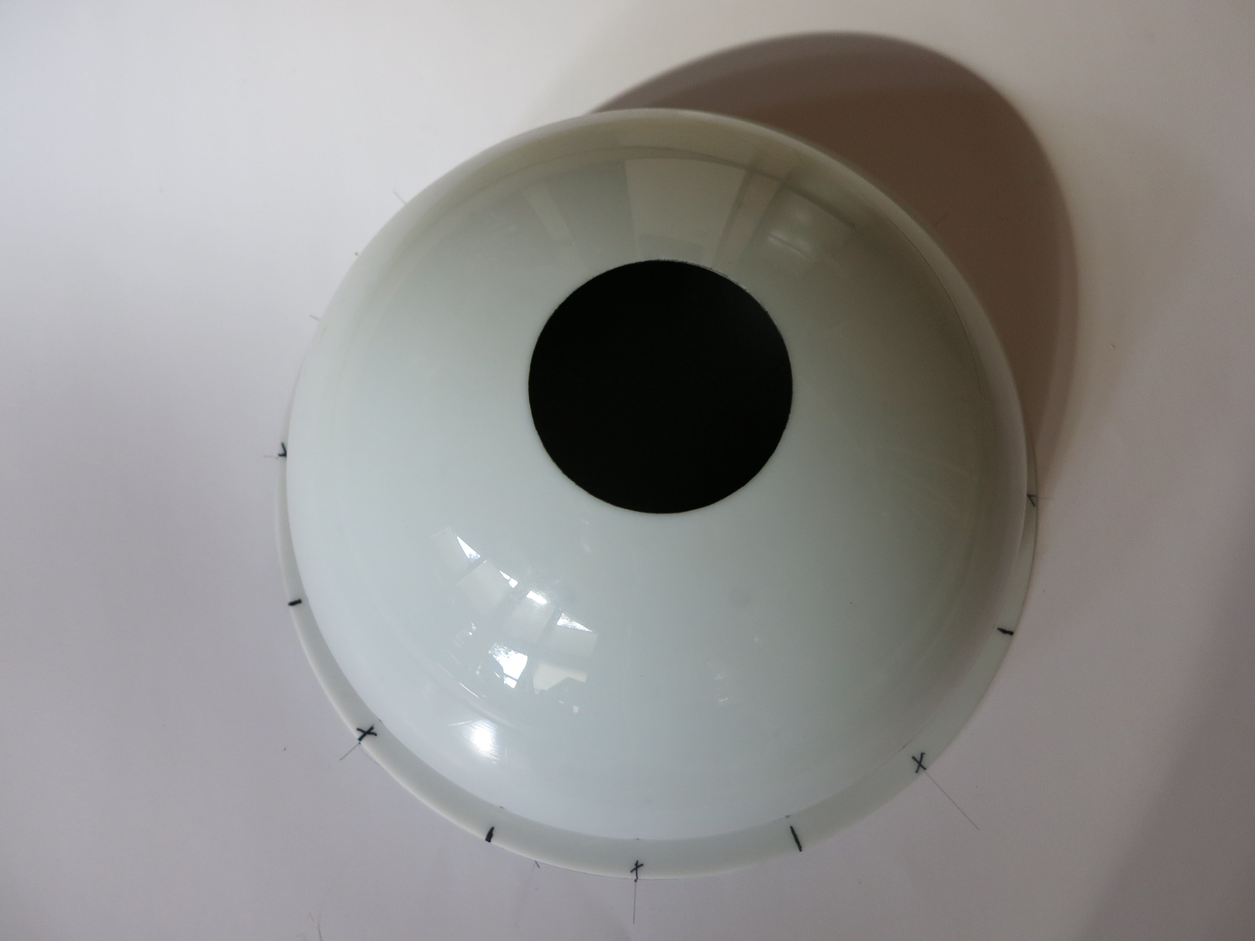
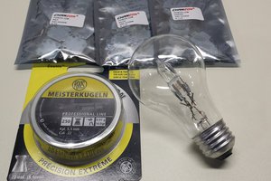
There are two common techniques for generating sets of photos for use in RTI. The manual technique is called Highlight-RTI, and requires manually moving a light source to different angles relative to an object (at a constant distance), and using a shiny reflective ball to determine the lighting angle (see the Cultural Heritage Imaging website for more info on this technique). While this non-automated technique doesn't require much in the way of special equipment, it's slow and cumbersome, and often requires two people to perform. The other technique, Dome-RTI, involves putting your object under a dome with multiple light sources on the inside, and a camera looking down through a hole at the object. An electronic controller turns lights on and off in sequence, and fires the camera shutter in sync with the lights. Because this technique is commonly fully automated, and because the lighting angles are always the same, obtaining the required photoset is much faster and easier with the Dome-RTI technique.
When I first started working with RTI in late 2012, there were no plans available to build such a dome system, only rough descriptions. There were several institutions (Cultural...
Read more »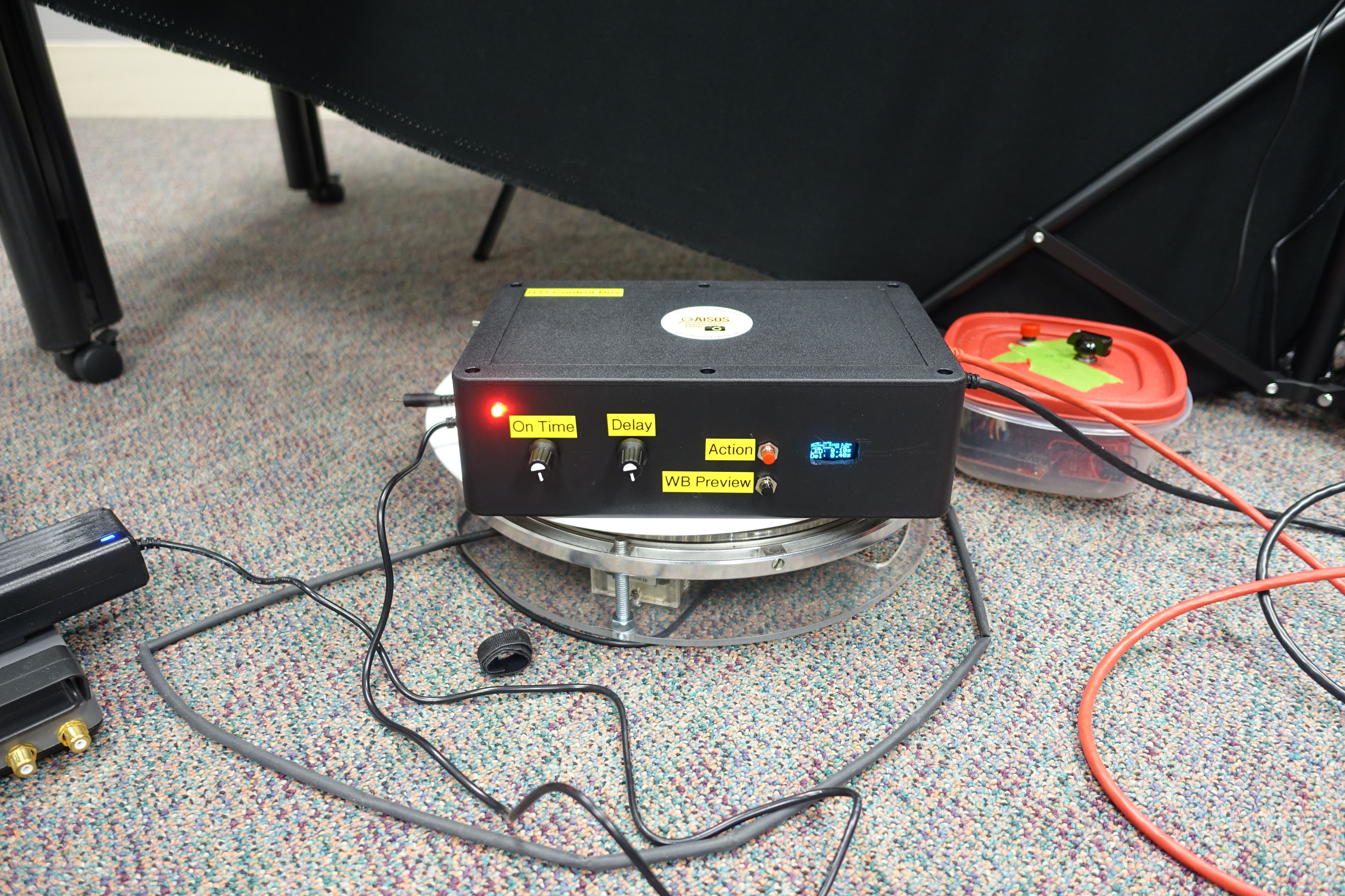
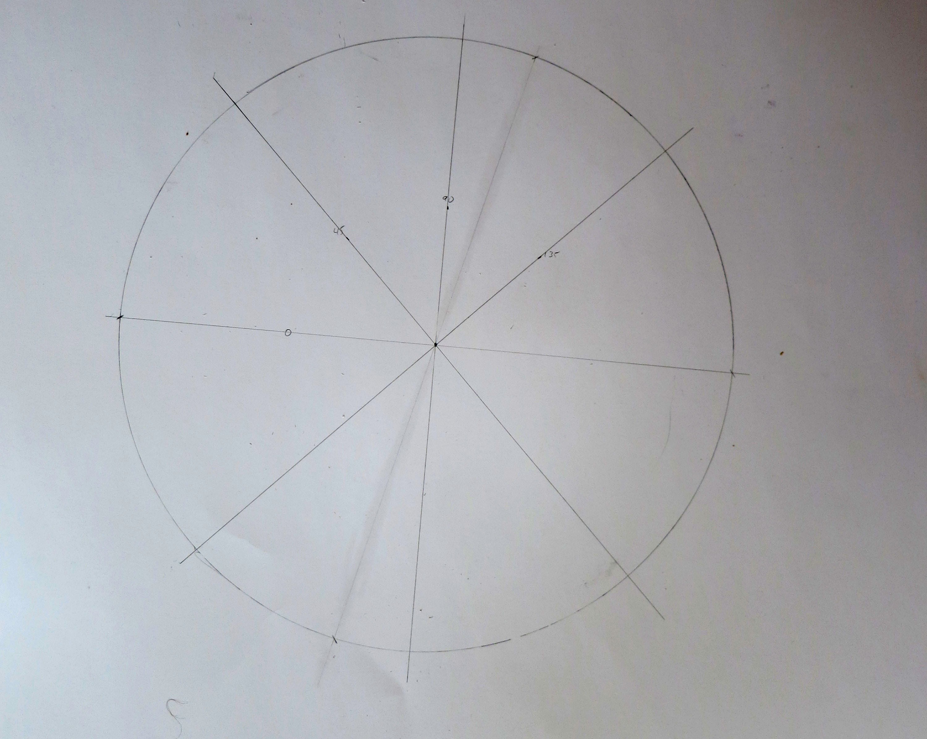
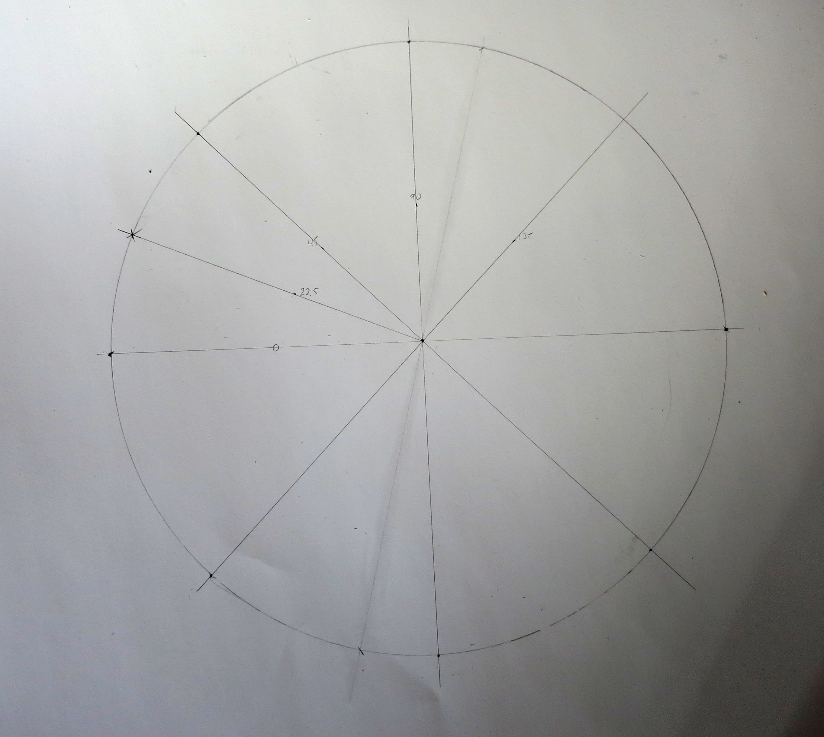
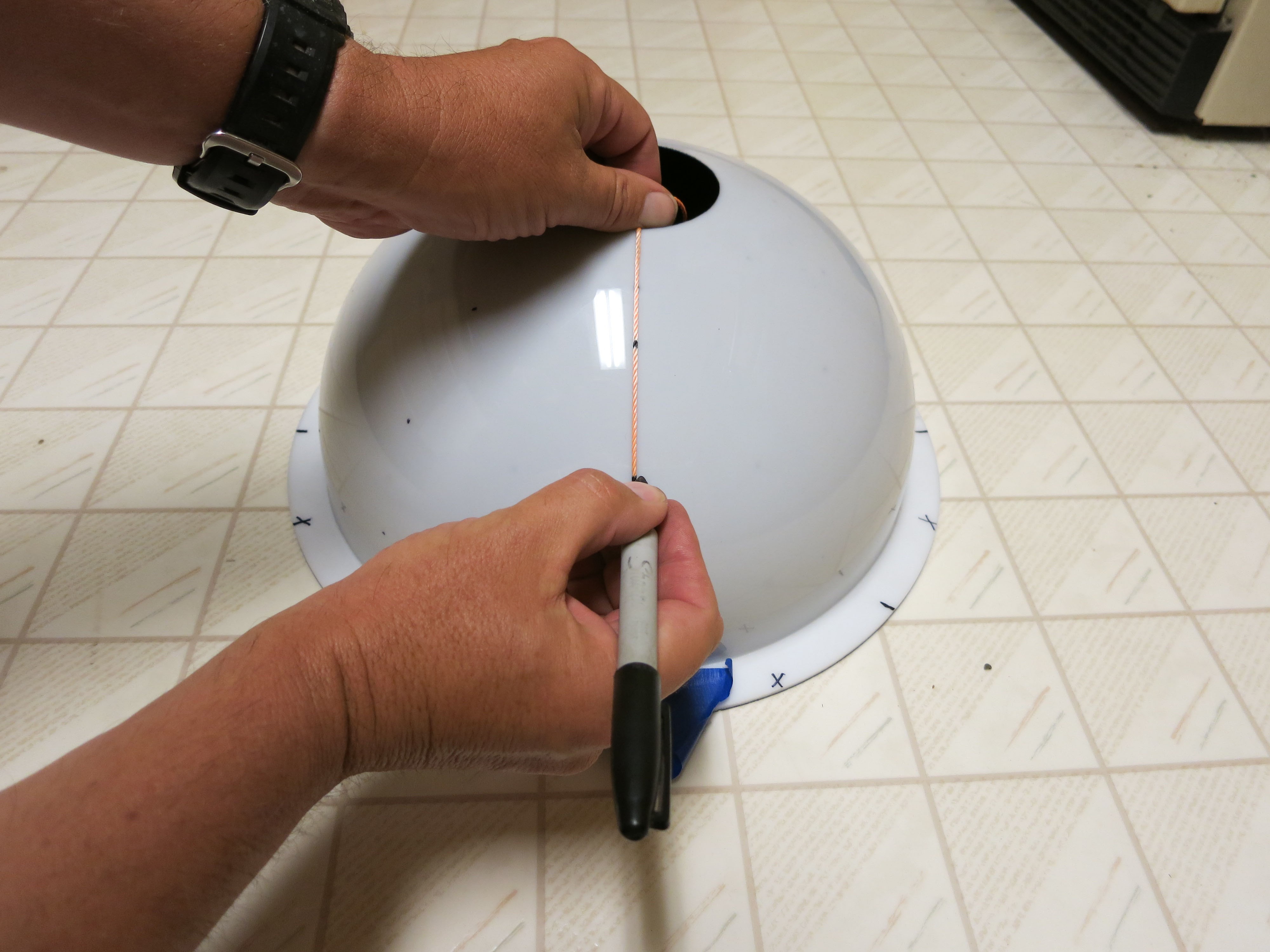
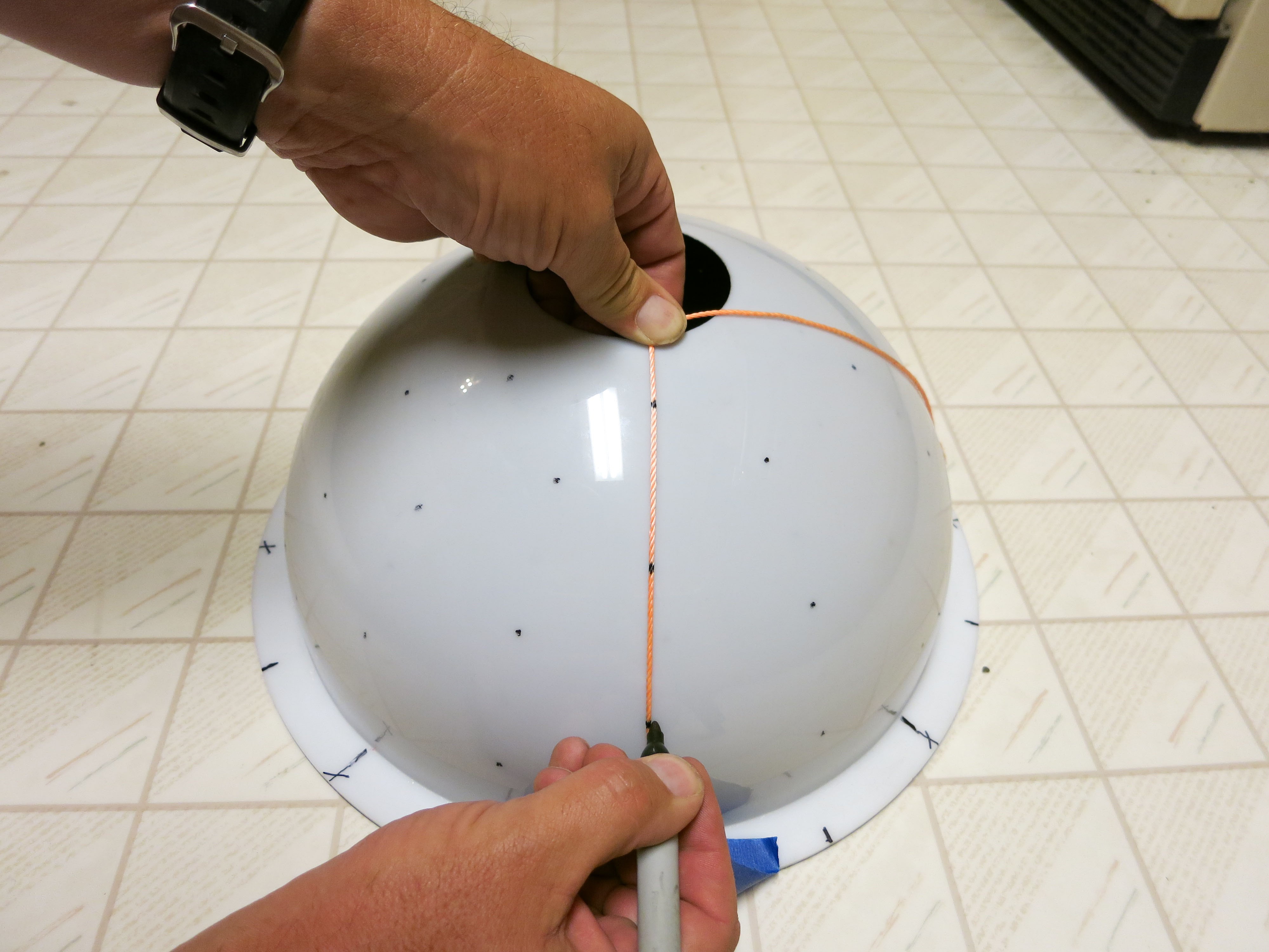
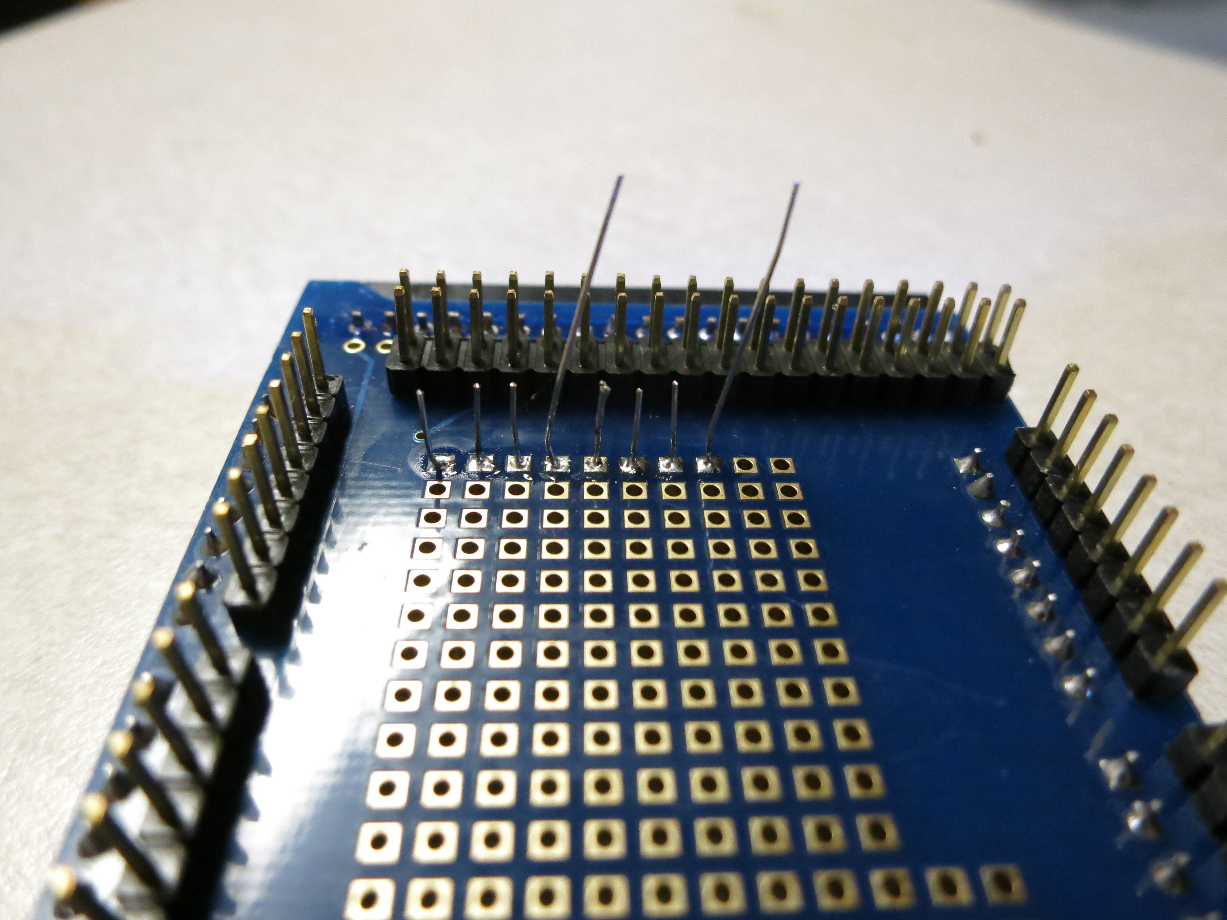
 Center found!

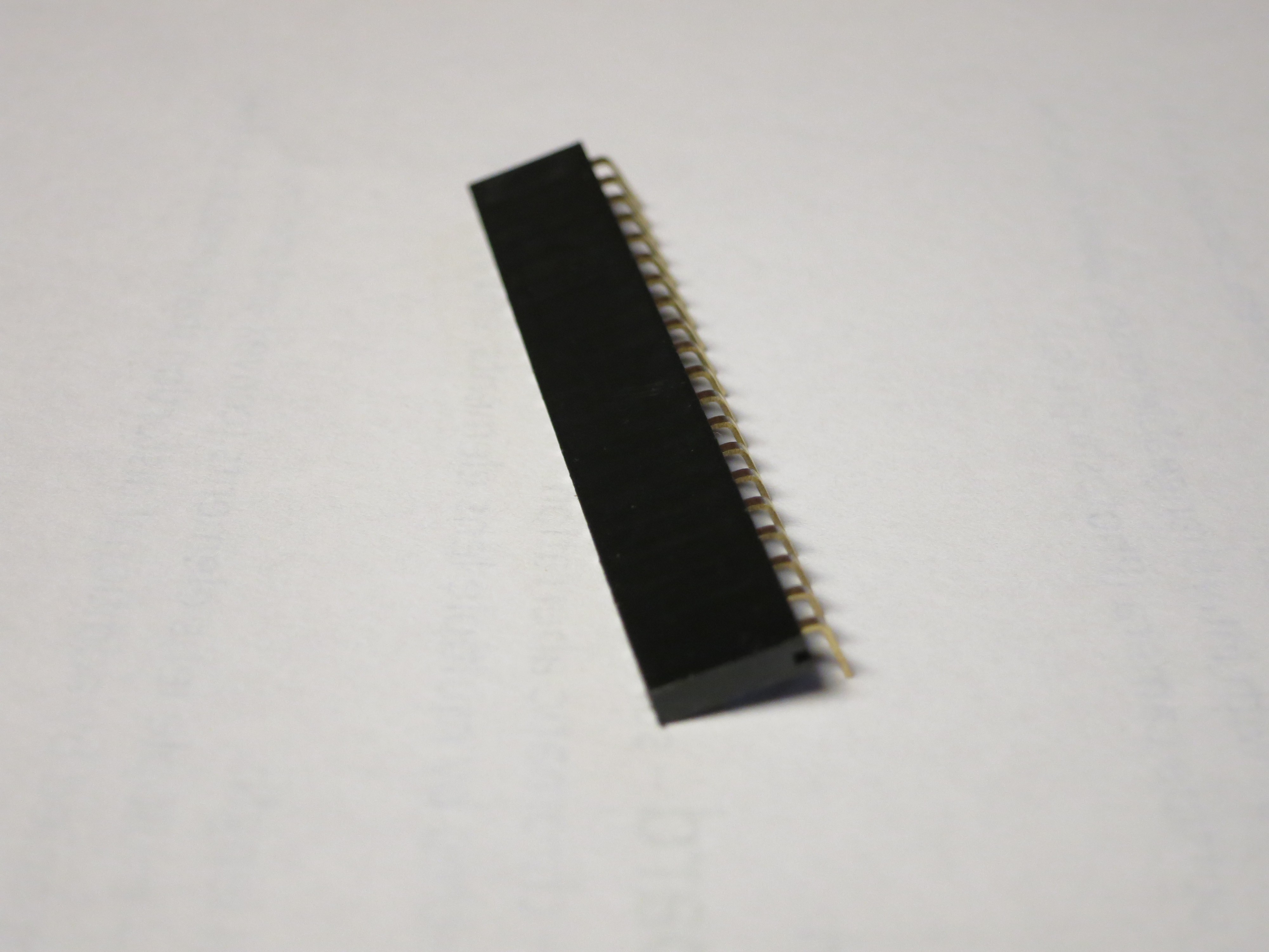

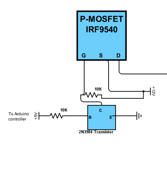
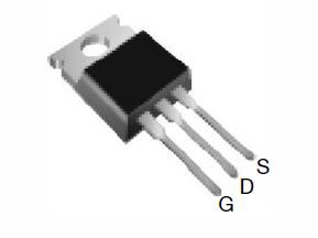 And here's a pic of the npn transistor:
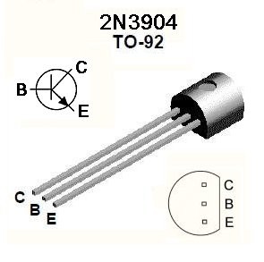


 Ted Yapo
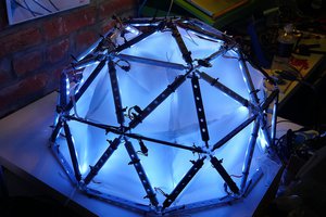
 Benjamin Blundell
 swimmingthestyx
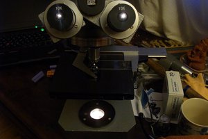
 andyhull
This is a really useful and cool ass project! I hope one day soon, to develop my own reflectance spectrometer for microscopy, impressive how much topography detail you are getting here.