Close
0%
0%

Arduino Pi: an Arduino computer for developers.

The Arduino Pi is a single board computer based on Arduino platform.

Similar projects worth following
The Arduino Pi is a single board computer based on Arduino. The Arduino Pi has a six button keyboard known as GKOS, which is an chorded keyboard, and has an LED matrix based display. Right now, the LED matrix is a 5x5 LED matrix that scrolls. This was designed small but will later expand to maybe an 8x8 LED matrix and then 16x32 LED display. It has 4 digital pins for development using the Arduino platform. The scripting language is called Bitlash. I used Bitlash because it was easier to implement in the Arduino sketch than other programming languages. This project is an ongoing project.

As part of the 2015 Hackaday Prize, the challenge is to solve a world problem. I believe this solves an important problem for developers but not sure whether it counts. I believe that it solves the problem of implementing an Raspberry Pi - like computing system with the Atmel developing system (Arduino).

GKOS Keypad

With the 6 GKOS keys, directly connected to Arduino I/O pins, it is possible to type any text and enter most functions found on the PC keyboard (Alt, Ctrl, Tab...).

GKOS Hardware

The GKOS hardware is very simple, requiring only six pushbuttons to be connected to Arduino pins and to ground. In the Arduino Pi project, the analog pins are used taking up all the analog pins (if Arduino Uno is used).

LED Matrix

The LED matrix is controlled using row-column scanning. 

LED matrices are often arranged in rows of common anodes and columns of common cathodes, or the reverse. Here's a typical example of an 8x8 matrix, and its schematic:
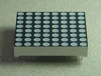
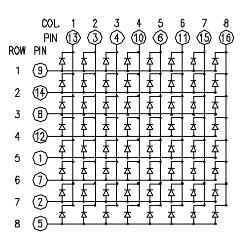
These can be very useful displays. To control a matrix, you connect both its rows and columns to your micro-controller. The columns are connected to the LEDs cathodes (see Figure 1), so a column needs to be high for any of the LEDs in that column to turn on. The rows are connected to the LEDs anodes, so the row needs to be low for an individual LED to turn on. 

To control an individual LED, you set its column high and its row low. To control multiple LEDs in a row, you set the rows high, then take the column high, then set the lows row or high as appropriate; a low row will turn the corresponding LED on, and a high row will turn it off.

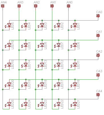
Similar schematic is used for a 5x5 LED matrix. I used the code from the below link :

http://www.instructables.com/id/5X5-dot-matrix-on-Arduino-gets-text-from-pc-2/

This link also includes the pixel maps for the 5x5 LED matrix.

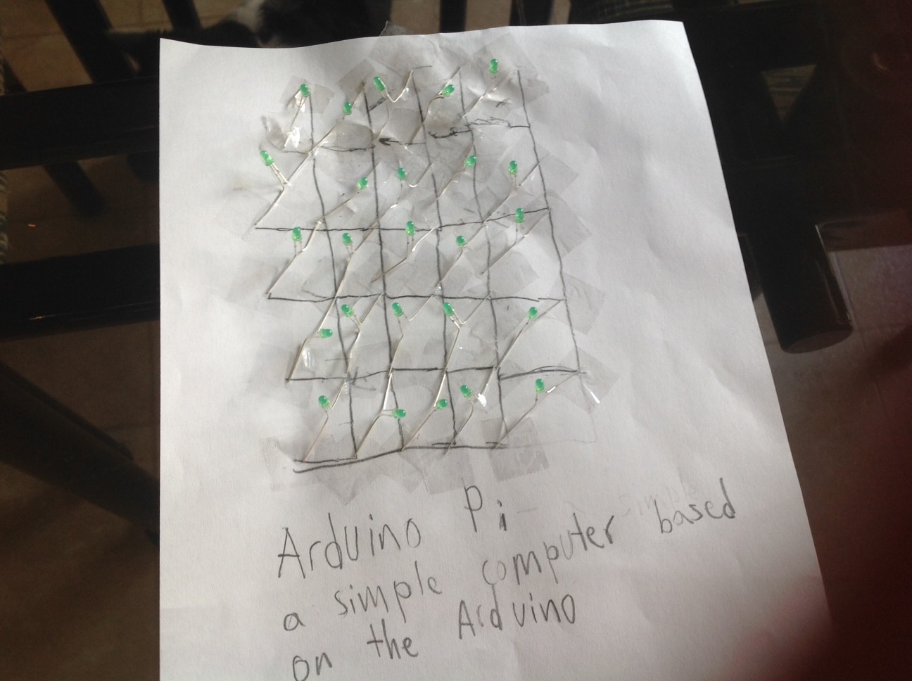
For the LED Matrix, I will construct the circuits on a piece of paper in which the graphite is the wire as graphite is conductive.

Bitlash

Bitlash is an open source interpreted language shell and embedded programming environment for Arduino. The Bitlash shell runs entirely on the Arduino and supports many of the familiar Arduino functions. Bitlash interprets commands you type on the serial port or send from your favorite PC-side programming environment. I have integrated Bitlash with the GKOS keypad so instead of using a serial port to enter commands, the GKOS keypad is used instead.

Bitlash Architecture

Bitlash website:

https://www.bitlash.net

Hardware schematics and pictures

Schematic:
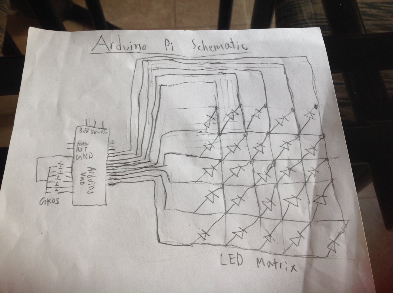
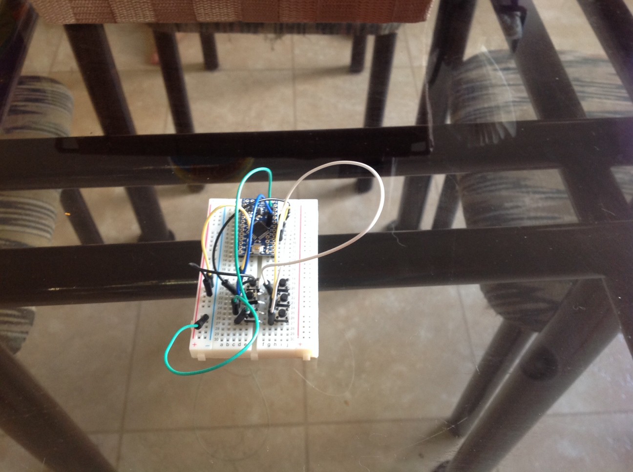
Breadboard:
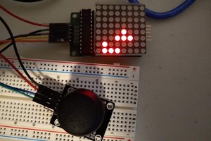
LED Matrix:
More Information

For more information, visit the official website at:

http://iscienceluvr.github.io/arduinopi

Stages and Goals

Stages of development and production (will be updated with when each stage was finished):

  • Stage 1 - Design (finished on June 3, 2014)
  • Stage 2 - Code Verification (finished on June 10, 2014)
  • Stage 3 - Part Ordering (finished on June 23, 2014)
  • Stage 4 - Hardware Verification
  • Stage 5 - PCB Testing and Production

Goals:

  • To create a cheaper DIY computer
  • To combine the best of Arduino and Raspberry Pi
  • To create a simpler electronics development board
  • 6 × Push button Any regular push button
  • 1 × Arduino Uno It's possible to use an atmega, decreasing the total price to about $7
  • 25 × LEDs Electronic Components / Misc. Electronic Components

  • LoL matrix

    bijtaj04/08/2015 at 04:03 0 comments

    Hello all,

    I got the LoL matrix board to help me organize the LEDs and simplify code. I will have to update many parts of this project, although most of it would probably work fine if someone can make a 5x5 matrix as I had described.

    bijtaj

  • Hackaday 2015 Prize

    bijtaj03/22/2015 at 18:01 0 comments

    Hello all,

    I will submit my project for the Hackaday 2015 Prize as well. However, I will need more components since my LED matrix doesn't work. Therefore, I need an 8x8 matrix and edit the code so it is compatible with the 8x8 LED matrix.

    bijtaj

  • Pictures for Arduino Pi

    bijtaj08/20/2014 at 17:27 0 comments

    Hello all,

    I just added some pics of the hardware and also of the schematic. You can see them in the details section.

    I am done with all the Hackaday Prize requirements! Please help me by sharing my project with others on Facebook, Twitter, Google+, etc. 

    Thanks,

    bijtaj

  • Video is up!

    bijtaj08/12/2014 at 02:46 0 comments

    Hello all!

    The video is up! Now the project is ready for the Hackaday Prize! You can see it in the Links section or in the Details.

    Thanks,

    bijtaj

  • LED Matrix done!

    bijtaj08/10/2014 at 01:22 0 comments

    Hello all!

    Finally, I'm almost done! The LED Matrix is done and I already finished the button and Arduino circuits on the breadboard. I just have to connect the two up and program it. The LED Matrix was complicated and the connections aren't perfect (using paper, pencil, and tape!). I would be surprised if the LED matrix works perfectly on its first try!

    I plan to post a video as soon as possible.

    Thanks,

    bijtaj

  • Slow Progress

    bijtaj07/26/2014 at 02:22 0 comments

    Hello all,

    I got the parts but I have been busy so I couldn't work on the project... I will post a video soon...

    bijtaj

  • Parts soon

    bijtaj06/24/2014 at 23:36 0 comments

    Parts will come tomorrow... I am exicted!! I will also work on an operating system soon by using the library that I designed.

    bijtaj

  • Library and possible larger LED display

    bijtaj06/13/2014 at 00:53 0 comments

    Hi all,

    For some time, I have been thinking of creating a bigger display. After all, a 5x5 LED matrix is too small. So I have decided to start working on a 20x10 LED display. The code will be similar, but a few additions will be needed. I will post schematic (although it will be very similar) and code.

    I have also just finished a library for the Arduino Pi. It is in the github repository under ArduinoPi folder. This can be used to control the ArduinoPi better. Also, I want to design and create an operating system so this library will simplify the creation of such an operating system.

    bijtaj

  • Code fixed!

    bijtaj06/10/2014 at 23:45 0 comments

    Hi all,

    The code has been debugged & fixed and it is in the github repository. My new code may seem a lot different from the original version but that's due to the difficulty with using the http://blog.duklabs.com/ code. Therefore, I used the code from the "5x5 LED matrix (gets text from pc)" instructables code. However, I will keep the link for people who wants to use LED matrices in different ways.

    Now moving on to next stages, part ordering and hardware verification!

    bijtaj

  • Coding help

    bijtaj06/09/2014 at 22:01 0 comments

    Hi all,

    I have to admit, although I like programming and I think that I'm good at it, I am not that great and so I am having problems fixing and debugging the code. One major error is due to the fact that gkos uses char* type and bitlash uses char type. So I always get an invalid conversion error.  So, it might take some time to finish code verification.

    If anyone wants to help, post your solutions in the comments for this project. It will be greatly appreciated. I will also acknowledge those who helped in my project.

    bijtaj

    P.S. I am going to order the components and parts soon. I am also thinking about creating a 16x8 LED matrix version. Hopefully, after I finsih code verification, I can write code for such a version soon.

View all 20 project logs

  • 1
    Step 1

    Get an Arduino, 6 pushbuttons, and 25 LEDs. Connect the pushbuttons to ground and to each of the analog pins.

  • 2
    Step 2

    Connect all the anodes together in each row and the cathodes together in each column like in the below schematic.

  • 3
    Step 3

    The anode rows should connect to digital pins 0-4 and the cathode columns should connect to digital pins 5-9. Based on the diagram in the previous steps, connect AN0 - AN4 to pins 0-4 and CA0- CA4 pins 5-9.

View all 5 instructions

Enjoy this project?

Share

Discussions

mohaned sonier wrote 08/15/2016 at 09:26 point

very good one to share, its very nice.

this connection are very organized,and that is good.

http://bramjak.com/2016/07/فتح-المواقع-المحجوبة/

  Are you sure? yes | no

Don wrote 08/06/2014 at 16:25 point
The project is interesting, but your project name and the image you use seem to be using Arduino and Raspberry Pi logos inappropriately.

  Are you sure? yes | no

bijtaj wrote 08/08/2014 at 03:22 point
What do you mean? I paid careful attention to abide with their rules for using their logos!

  Are you sure? yes | no

Don wrote 08/08/2014 at 17:38 point
I don't mean for any of this to detract from your very cool project and this is the last time I'll say anything about trademarks here, because, really the hacks are the important part!

From the Raspberry Pi website:

"3. When can’t I use the Raspberry Pi Marks?
You may not:
(i) use the Raspberry Pi Marks as part of your company name, company logo or product name;
..."

From the Arduino website:
"Arduino" is a trademark of Arduino team and should not be used for unofficial variants."

The Arduino Community logo seems like it would be okay if you didn't have the RaspBerry Pi logo embedded in the user-specific area, maybe with the word Pi in it's place.

Maybe I'm misinterpreting, since I'm not a lawyer.

  Are you sure? yes | no

dwHacks wrote 07/04/2014 at 19:56 point
I believe by "connectedness" they mean to a network of sorts, ie. the internet.

Great project though!

  Are you sure? yes | no

bijtaj wrote 07/09/2014 at 22:15 point
Yes, i'm working on internet connection as well!

  Are you sure? yes | no

Adam Fabio wrote 06/17/2014 at 03:15 point
Great Project bijtaj! Thanks for submitting it to The Hackaday Prize. Can't wait to see where you go with the Arduino Pi. Don't forget about the "connectedness" portion of the competition, it's not a requirement, but will definitely help you on the road to Space!

  Are you sure? yes | no

bijtaj wrote 06/27/2014 at 16:51 point
Thanks for the encouraging words! I didn't understand about the "connectedness" part... can you explain it to me?

  Are you sure? yes | no

Similar Projects

Does this project spark your interest?

Become a member to follow this project and never miss any updates