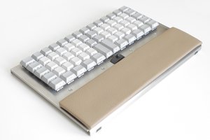
The keyboard is heavy. And it was clear from the orientation of the main QWERTY portion that it is intended to be mounted at an angle. Each key has a long travel and feels very solid as they are depressed. They don't have the "click" of an IBM M keyboard but feel very satisfying none-the-less. The PCB is 2-layer and obviously hand-drawn with curved traces and a very interesting array of vertical and horizontal wavy traces at the top where a large number of jumpers in vias between the top and bottom had been added manually to create a specific set of key to XY mappings.
There is one IC, a couple of filter capacitors and a set of pull-up or pull-down resistors on a parallel bus. Signals from the IC are wired to one side of a PCB connector. Signals from the keys themselves are wired to the other side of the connector and another connector at the other side of the PCB. It is (or seemed) obvious which connector pins supply power to the IC. A 15 uF electrolytic capacitor with a 35 VDC rating was no help deciding what voltage the IC ran at. There are 15 signals from the IC that go to the connector. Two connected to the large power traces and the rest to the keyboard array. It was easy to guess that the IC output keyboard data in some sort of parallel fashion.
I could not make out the part number on the IC but I could tell it was manufactured by AMI. I did a bunch of online research and found out that AMI made a series of keyboard encoders in the 1970s but no datasheets for these parts exist today. I could find nothing that resembled the part on my keyboard.
I decided to apply some power to see what would happen. My keyboard had a 1974 date-code and I figured that keyboards of that era would have been powered by +5 volts with a parallel output of some kind (although I was a little confused by the fact that my keyboard had 15 apparent data signals going to the edge connector - my research indicated that they usually had 7 data signals plus a strobe and maybe parity). The electrolytic capacitor indicated the polarity and a quick DMM measurement indicated no short so I applied +5 volts with a 100 mA limit. The PSU immediately went into current limiting mode. hmm.... I looked and looked and didn't see any apparent shorts. Then I noticed that every key had 4 IOs and two of the IOs were connected to power! What?!?! More research and I learned about hall-effect key switches. Apparently these are sort-of the Cadillac of key switches. Each key has a hall-effect sensor (IC) and a magnet. They are incredibly reliable because all the key has to do is move the magnet over the sensor. No contacts to corrode or break down. Each key takes power and has one or two outputs that pulse when the magnet moves past the sensor. Typically each key has two open-drain outputs that go low simultaneously when the key is pressed. The two outputs are used in a XY array for an external encoder chip. One of the really cool attributes of hall-effect keys, I read, was that they don't need to be debounced. The sensor IC has hysteresis and generates a clean signal upon each keypress. Another cool attribute is that the keyboard has inherent N-key rollover.
I upped my PSU current limit to an amp and powered up again. This time it maintained 5 volts and was supplying just over 400 mA. Nothing got hot and the current remained steady. I figured that was a good sign; all the keys on the keyboard required quite a bit of current. But then I thought about the machine(s) this keyboard might have been part of in 1974 and realized that 400 mA for the keyboard was probably nothing compared to the power-budget of the entire machine.
Next up was to see if I could see anything on the signals coming from the keyboard. I started with an oscilloscope and looked at each signal while pressing various keys. Nothing. Some signals appeared to be logic high and some signals appeared to be logic low but nothing changed, no matter what I did to the keyboard. I then probed the two outputs of each button....
Almost pre-historic computer keyboard lives again
The story of resurrecting a very old, but wonderfully tactile, keyboard found in a barn.
 Dan Julio



 deʃhipu
 Arya
Arya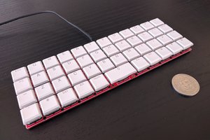
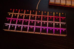
dude, nice honeywell keeb... i have some honeywell hall effect switches,... going to try to make a keyboard out of it...plank layout
did you find that you needed to power the switches all the time or just when strobed?...I think i want to do it with a teensy but haven't tested if the switch can work just like a regular switch yet