Close
0%
0%

PURE modules

Simplifying development of low power wireless IoT hardware and software sensor prototypes with a modular sensor architecture

Similar projects worth following
By standardizing the interconnect method to a low cost standard, everyone can make low cost compatible modules that are quick and easy to assemble.

PUREmodules.com attempt to simplify developing (low power wireless) sensor prototyping.

Featured on Hackaday Blog Here: http://hackaday.com/2016/12/25/pure-modules-aim-to-make-prototyping-easier/

What is this?

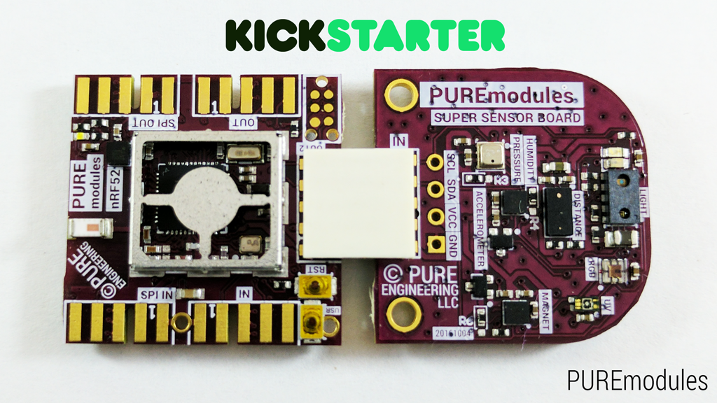
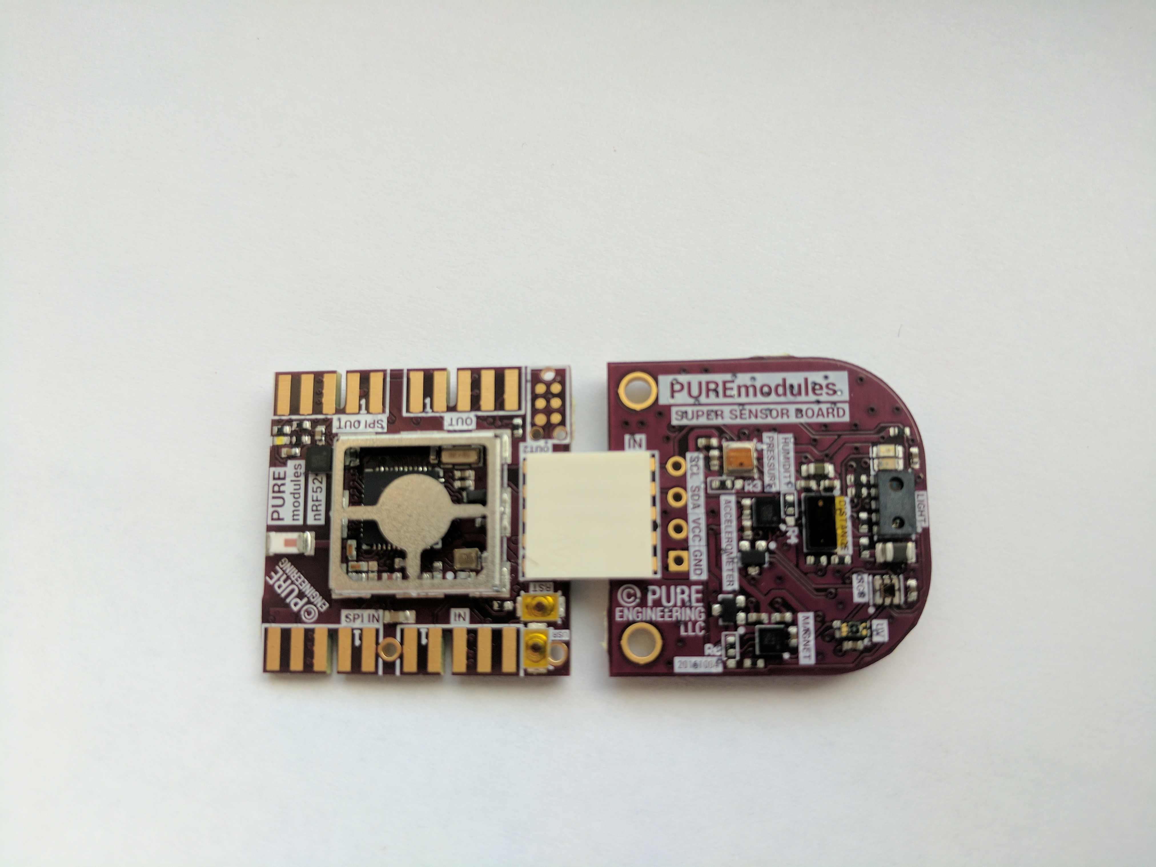
The goal is to make easy to plug together sensors to make something new and interesting quickly. Typically one uses a breadboard, but this is not very field-able and wires easily pull out. Also having something small is much nicer to use than something bulky. Also making PCB's is getting easier these days. So when you make a new sensor why not add a simple edge mount PCB pattern that enables your to connect to an ecosystem of other sensors.

Common Hardware Interconnect

To allow for prototypes to be small and low cost we have chosen a 62mil PCB edge connector as the hardware interface. This interface has 0 components to be added to a PCB to allow it to connect to the system by a low cost connector. By using a PCB edge the costs remain low for the sensor and can be added to nearly any development board with no additional cost.

The 009159010061916 AVX Open Ended Card Edge: BTB was chosen as the default interface to connect two PCB's together. The connection is very robust and allows for many insertions and can carry higher currents if needed. The density is high and doesn't use very much PCB real estate.

We have chosen I2C to be the primary interface to adding new sensors to the system. I2C was chosen for its simple two wire interface and multi drop architecture. The protocol is typically used for low power hardware sensors, so for most common sensors there is no interconnect logic.

The common pin-out is as follows

  1. VCC system, 2-3.3V range. typically could be directly tied to a lithium coin cell or two AA's in series
  2. RAW battery, 3.3V-15V range. cound be a li-ion battery, wall wart, solar cells, etc. this raw battery is typically regulated down to 3V-3.3V
  3. GND, Common ground reference point
  4. SDA.
  5. SCK
  6. GPIO (typically would be the uart TX from the micro-controller)
  7. GPIO (typically would be the uart RX to the micro-controller)
  8. GPIO
  9. GPIO
  10. GPIO (typically this connects to an interrupt open collector bus to the micro-controller

Common Firmware platform

We have chosen contiki as the the foundation for the system. Contiki has been used for many years now and is very stable and well supported. It was designed around low power, low resource, wireless systems. This is an ideal fit for a Modular Sensor Architecture.

Common Sensor Communication

MQTT was chosen as the data transport layer due to its extremely lightweight overhead. It easily allows scaling from one sensor to millions. It is well used and supported. Both MQTT and MQTT-sn are utilized depending on the RF communication interface. MQTT-sn is typically used over MQTT due to its lower overhead.

Common Data protocol

To describe data moving from A->B Protocol Buffers and more specifically nanoPb is used. By using a compact and common protocol data can be digested by almost anything simply by publishing your .proto file.

Common Micro Controllers

We have chosen two micro controllers to be the primary supported micro-controllers under this sensor architecture.

nrf52 : Nordic's latest SoC had handle almost anything thrown at it and still remain a low power.

cc2650: TI novel three core architecture allows for extremely low power systems.

Analog Sensors

For adding Analog sensors to the system, the preferred route is using an I2C ADC converter chip. we highly recommend the ADS7924 due to its low power standby current and the ability to control the power of the analog sensors to reduce power usage. The Mics 6814 sensor module uses this chip.

Extra GPIO

We highly recommend the Semtech SX1508B GPIO chip. This chip is very versatile and low power. it most likely can do what you need. We recommend using this I2C GPIO over the micro-controller pins mainly to keep your pin count low and flexible. Also this IC provides level shifting if needed and when going to low power sleep states, you won't have to mess with the GPIO states of the micro-controller. Lastly by using I2C instead of pin on the controller we can expand to a complex system very easily.

UART expansion...

Read more »

JPEG Image - 616.05 kB - 09/05/2016 at 15:45

Preview
Download

JPEG Image - 664.94 kB - 09/05/2016 at 15:45

Preview
Download

modules_in_arduino.jpg

Plugged into an Arduino

JPEG Image - 1.44 MB - 09/05/2016 at 15:40

Preview
Download

  • 1 × CC2650
  • 1 × Grid-eye

  • IuT ! IoT

    Pure Engineering03/21/2017 at 21:11 0 comments

    I think this is a good project for the IuT ! IoT submission.

    I'll post up some applications using the modular IoT hardware in the coming weeks.

  • Kickstarter 100 backers

    Pure Engineering01/13/2017 at 22:29 0 comments

    Just crossed the 100 backer mark. A few days left...

  • Made it to Hackaday main page :)

    Pure Engineering12/25/2016 at 22:28 0 comments
  • Made it to Hackaday main page :)

    Pure Engineering12/25/2016 at 22:28 0 comments
  • Kickstarter live session posted

    Pure Engineering12/12/2016 at 16:45 1 comment
  • 7 Advantages of prototyping with modular hardware

    Pure Engineering12/10/2016 at 01:12 0 comments

    1. Reuse tested hardware and software. The first time you do anything it always takes longer than you expected. There is a magnitude of things that can go wrong or were not planned. By starting with known working hardware, you can reduce the number of variables. Firmware for hardware takes time to work out all the bugs to make is reliable under all the operating states. Not only that but if you are writing firmware drivers and you have interment hardware you can literally go crazy troubleshooting your code, when the hardware is at fault. By starting with a known starting point your risk is greatly reduced.
    2. Quick to illiterate and experiment. If a design is modular you can try out new ideas until you figure out something that works well. You can build several versions of the hardware and see which path is the best one. If there are several sensors that do the same thing you can compare them side by side. The power to experiment provides a way to discover new ideas and truly innovate.
    3. Easy to pivot if something goes wrong. Murphy’s Law is always in effect, even the best designs can have unforeseen issues once put into play. With a modular design, you can swap out what doesn’t work and replace it with something else with minimal disruption of the rest of the design.
    4. Make a custom solution to the problem. When prototyping with a typical development board, they typically attempt to include every possible interface on one large circuit board. Often is the case you only need a few of them, and the rest is unneeded. The development board also includes power supplies and other support logic that may not apply or go against your design. This often makes a large bulky solution that can make prototyping difficult in some cases to large or inconvenient to test. With a modular hardware design, you just choose what you need without all the extra bulk, also since each block is chosen for your solution you have exactly what you need and is truly a custom solution.
    5. Minimize time and money designing hardware. Designing custom hardware is expensive and time consuming. The typical design process can take many weeks for a simple design, and unlike compiling code it takes weeks to try out each version to make sure it works. Often the first version of hardware doesn’t work the way you intended and you need to repeat the process several times. If you can just pick and choose from a list of proven designs this is a huge time savings.
    6. Only design what you need. If there exists modular hardware for 99% of your design, then you can greatly reduce the focus of your hardware design to just the 1% that is different. Now 100% of your time can be devoted to making your 1% as best as possible without worrying about everything else.
    7. Lower your risk before you make your final design. Once you have prototyped your entire design, you can write all your software as if was running on production hardware. Because of this you know it will work the way you designed. You can show it to potential investors and customers and get early feedback that is invaluable. The confidence of a proven working prototype that is close to the final design allows smart business decisions to be made rather than gambling and hoping that things go as you planned.

  • PUREmodules on Geeky Gadgets

    Pure Engineering11/30/2016 at 19:25 0 comments
  • PUREmodules Kickstarter on kicktraq

    Pure Engineering11/30/2016 at 17:24 0 comments

    Making progress to the goal. Thanks for everyone backing so far and everyone sharing the project.

    PUREmodules… for dreamers, tinkerers, hackers and designers -- Kicktraq Mini

  • PUREmodules kickstarter

    Pure Engineering11/28/2016 at 17:18 0 comments
  • nRF52 Core module

    Pure Engineering10/30/2016 at 13:57 0 comments

    new arrival. Now we have a core and the super sensor together.

View all 30 project logs

Enjoy this project?

Share

Discussions

Similar Projects

Does this project spark your interest?

Become a member to follow this project and never miss any updates