 Dimitri Synodinos
what you need:
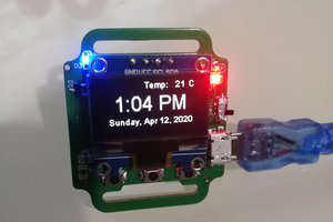
1. arduIoT U1 board from arduIoT.com
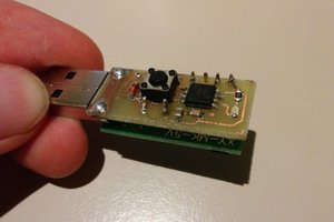
2. a FDTI232 USB to UART programmer or any other programmer
3. USB cable
4. latest verstion of arduino IDE
5. Library for U1. Download the latest library from U1 library. Online manual, more examples and help for all the functions that can be used in the library can be found here.
6. A 24v power supply
7. 4x water values
8. A step down from 24v to 12v, or a 12v power supply
9. 4x relay or to build your own PCB with mosfet. PCB is design with fritzing
How to load sketch:
1. connect FTDI
2. install latest verstion of arduino IDE and the arduIoT library. Info on how to install can be found at arduIoT.com 'softare setup'. Manual for all the functions of the library, more examples, and help can also found.
3. on arduino IDE goto File->Examples->arduIoT->g.Applications->irrigation->Run first EEPROM upload
4. press upload and open the Serial terminal. This sketch uploads all the strings to the EEPROM. ATMEGA328 has a low memory size, and all the strings that are used will take up all the memory.
5. on arduino IDE goto File->Examples->arduIoT->g.Applications->irrigation->Program.
6. press upload to upload the final sketch to the arduIoT U1.
You are done uploading the software. Work with the menu and test the pins D2,D3,D5,D6. Those are the 4 pins used for the 4 valves.
Relay solution (easy):
connect your relays with the arduiot by using the pins D2 D3 D5 D6. Do not forget to connect the ground of the relays with the ground of the arduIoT U1.
On the switch side of the relay connect the valves and the 24v power supply. Google for more info how to connect a device to a relay.
power up the arduIoT U1 with 12V.
you are done controlling your valves.
Build Custom PCB (nicer! but....you have to build a PCB:
On the .ZIP files you will find the fritzing file, and the Copper PDFs
On the power plug you use 24v, and you can use any stepdown power supply to power the ArduIoT U1.
On the other side you connect the 4 water valves.
 Sagar 001
 Pat Hogan