kodera2t
-
Evolution of my struggling with ATmega4809
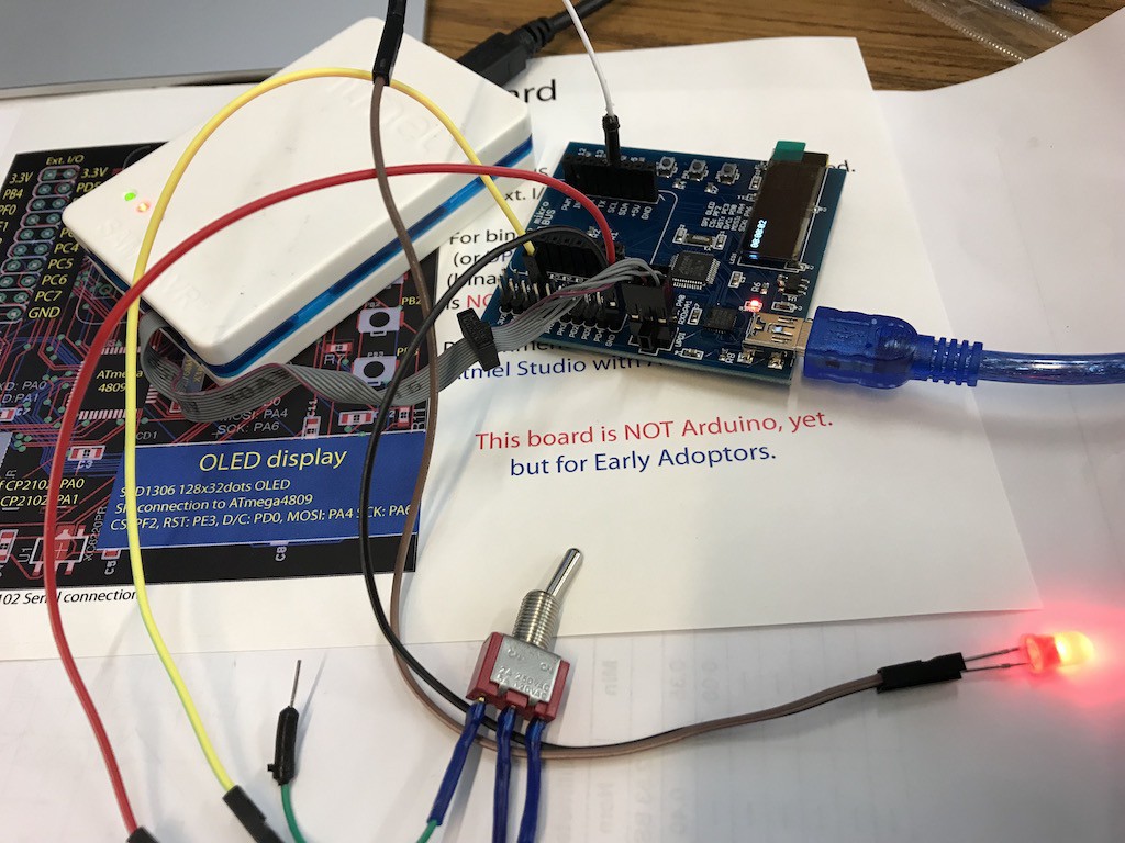
04/14/2018 at 09:39 • 0 comments![]()
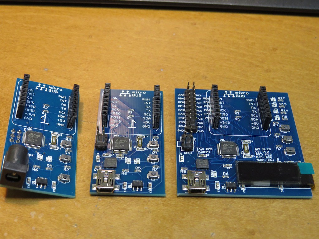
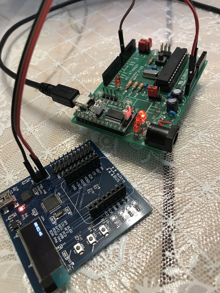
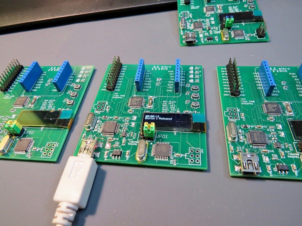
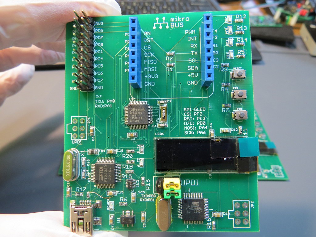
Actually I have already several "not released" prototyping board. The first one (left of the above) is simple board with 3.3V LDO and 3-tact switch and MikroBus interface. The power is applied through "barrel" connector. The binary is uploaded through UPDI, indeed single wire, interface through Atmel ICE. At this stage, I noticed the importance of USB-UART interface and evolved to the next stage (mid of the above picture). It is pleasantly and comfortably working for checking and testing. But I am "OLED lover". Also the sample program on RTOS delivered by Microchip supports OLED display so the board has the evolution for checking it! (the right of the above picture).
The OLED is connected through SPI with ATmega4809 and as same as previous two version, still binary uploading needs the help of Atmel ICE. But I hope (may be not ?) Arduino.cc will make bootloader supporting UART binary uploading and the DTR of CP2102 is connected to RST of ATmega4809 through 0.1uF capacitor, believing AVR traditional.
If you want to make board with ATmega4809, please use my Eagle library of ATmega4809. The file name of it is "microwavemont_ATMega4809.lbr" will be found in the above link.
![]()
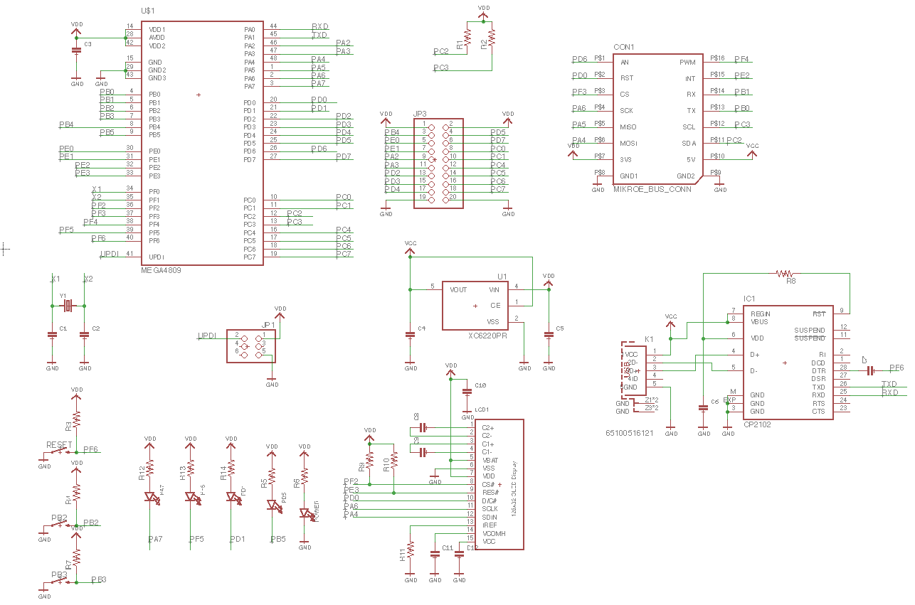
It's no worth to imitate this but the circuit is like above. All of the pin has a pin-out or connected to certain devices. In the circuit you will see UPDI 6-pin interface. YES, it is really single pin connection, even without RESET....
![]()
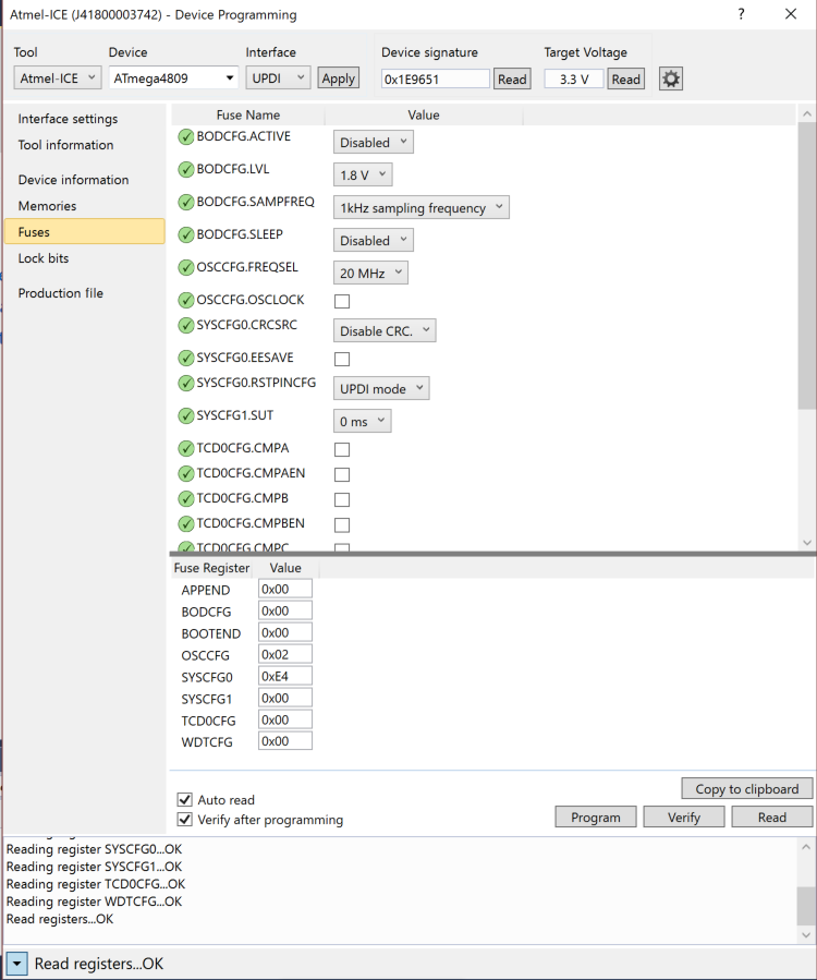
Device recognition is as shown above. As a proof of AVR, it has Fuse bit!, but indeed ATmega4809 is more similar to ATXmega, not general AVR like Mega328 or Tiny series in the programming manner. (You will see if you touch this chip., like DDRB is not accepted by ATMega4809 but PORTB.DIRSET)..
Here is quick comparison between:
Mega,Tiny ATMega4809 Port direction DDRB PORTB.DIRSET Value definition PORTB PORTB.OUTSET Actually I have no experience of Xmega, but enjoying ATmega4809 needs several knowledge of Xmega, not well-known simple AVR..
-
Introduction movie is on youtube
04/14/2018 at 12:29 • 0 commentsHere we can see the operation of the board. Every three version requires Atmel ICE for UPDI binary uploading. But by googling by the word "UPDI", I've found several implementation by various ways (one of them are on Arduino sketch, Mega328P is working as a converter from serial to UPDI !, great). I thought, the forthcoming next Arduino will be implemented by the same way as conventional Mega328P (like DTR-RST connection through capacitor), but I can add one prediction, 32U4 or something with USB and it may talk with 4809 via UPDI...
By the way, I have a naive question
![]()
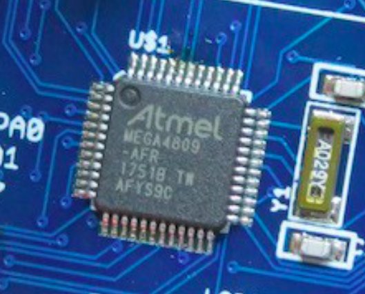
Why Microchip still release new chip by "Atmel" logo? Atmel logo will remain?
-
How to start project on your 4809 Explorer board
04/16/2018 at 04:52 • 0 comments![]()
I made several experimental board (may be delivered on my tindie store) and here I would like to explain how to start project with this board on Atmel Studio with Atmel ICE.
![]()
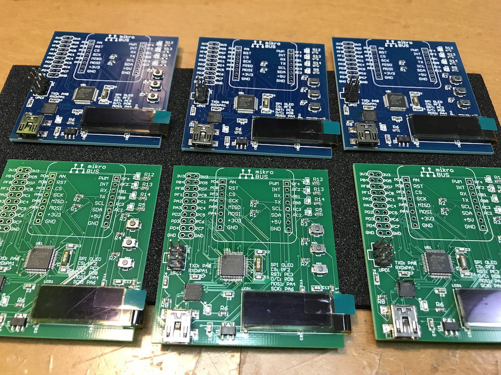
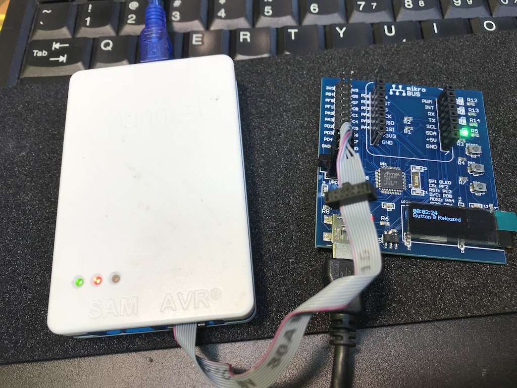
First of all, we need to install Atmel Studio (if not yet) and connect it to the onboard UPDI connector. The board is USB bus power so we need additional USB cable connection from your PC to the board.
![]()
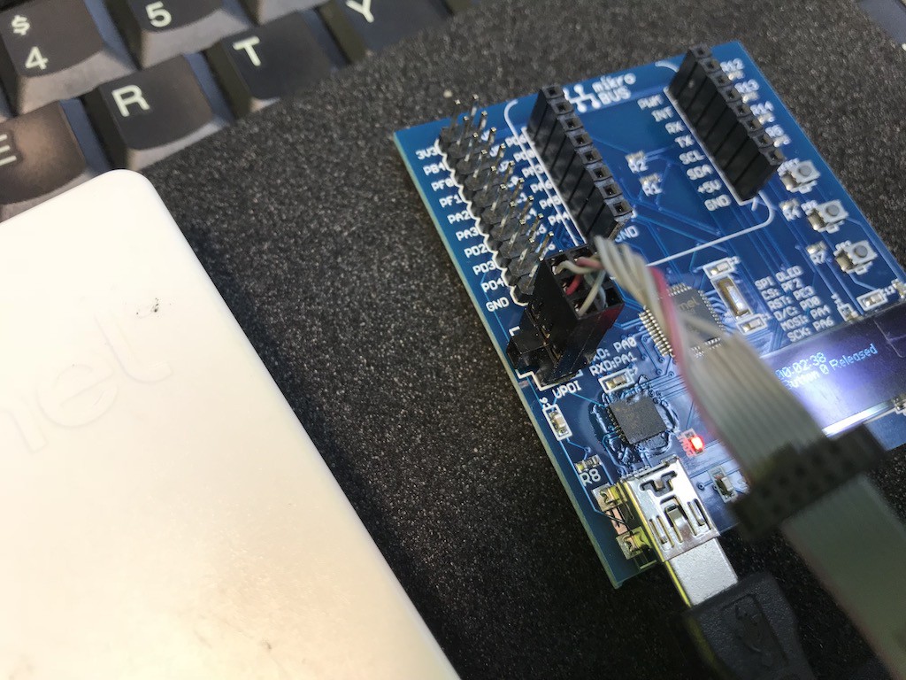
UPDI connector has a right direction so please follow the onboard guideline.
![]()
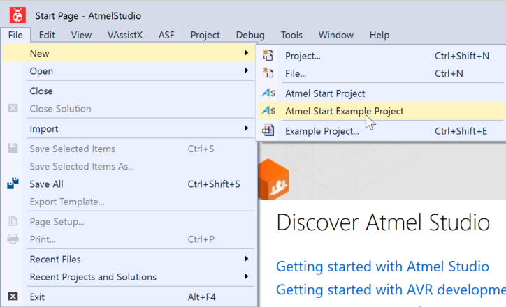
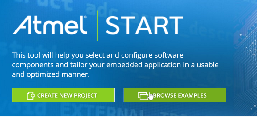
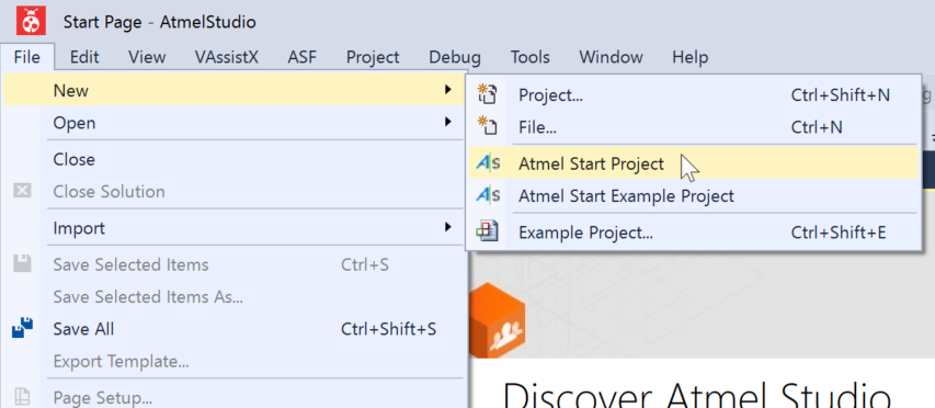
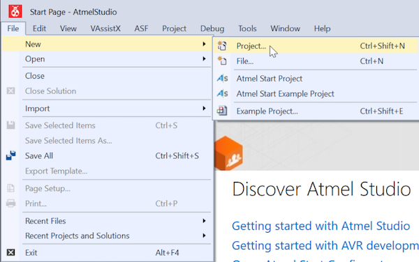
Now let's start Atmel Studio and select "Atmel Start Example Project"
![]()
and click "Browse Examples"
![]()
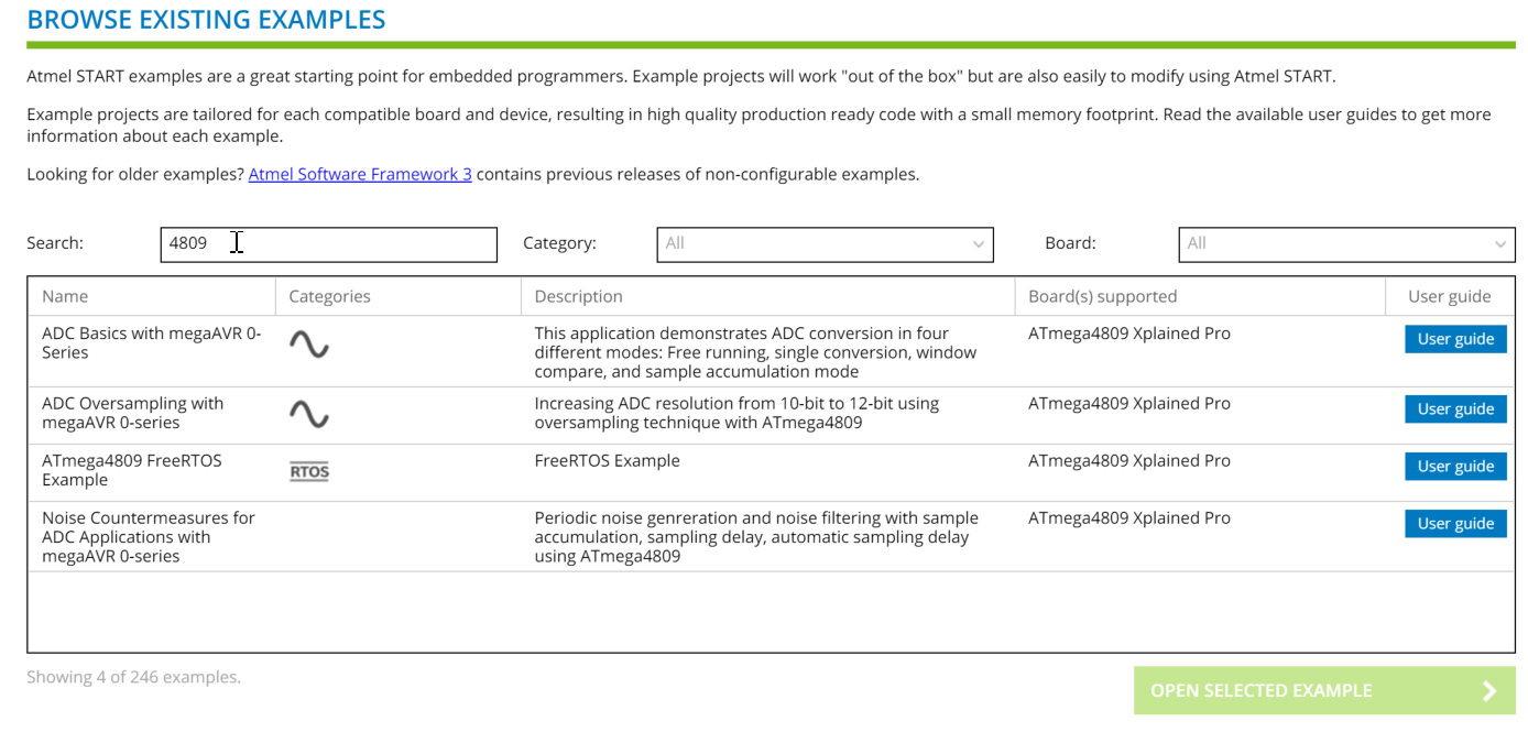
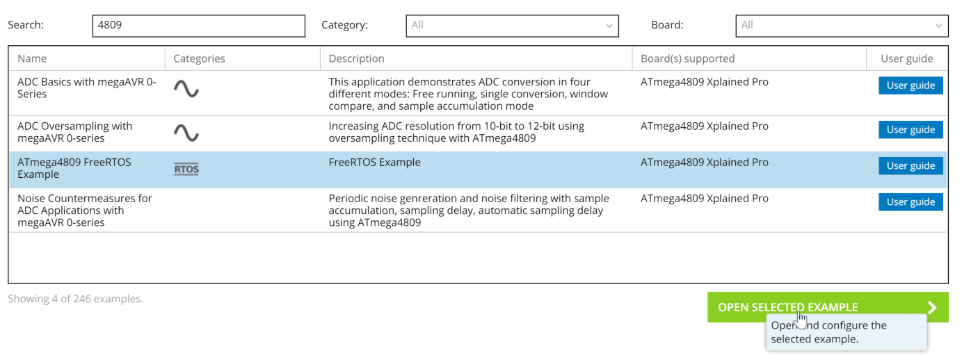
Just entering "4809" as the search word, you will find 4 examples. (still not so much, indeed.)
![]()
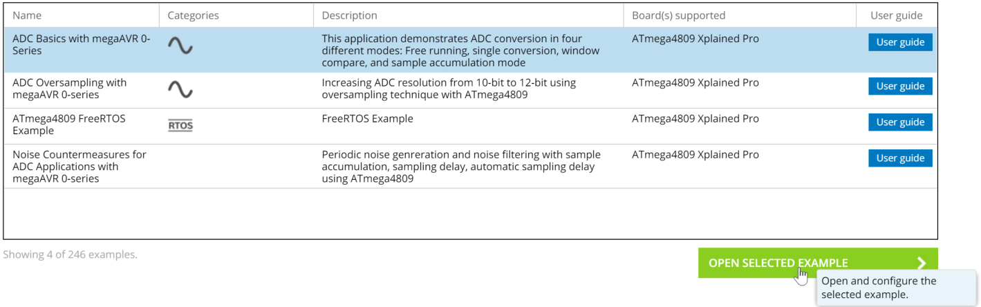
Now let's select the first "ADC Basics with megaAVR 0-Series" and click "Open Selected Example"
![]()
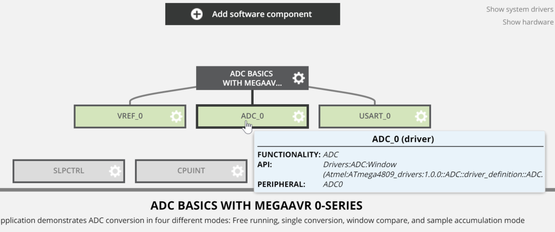
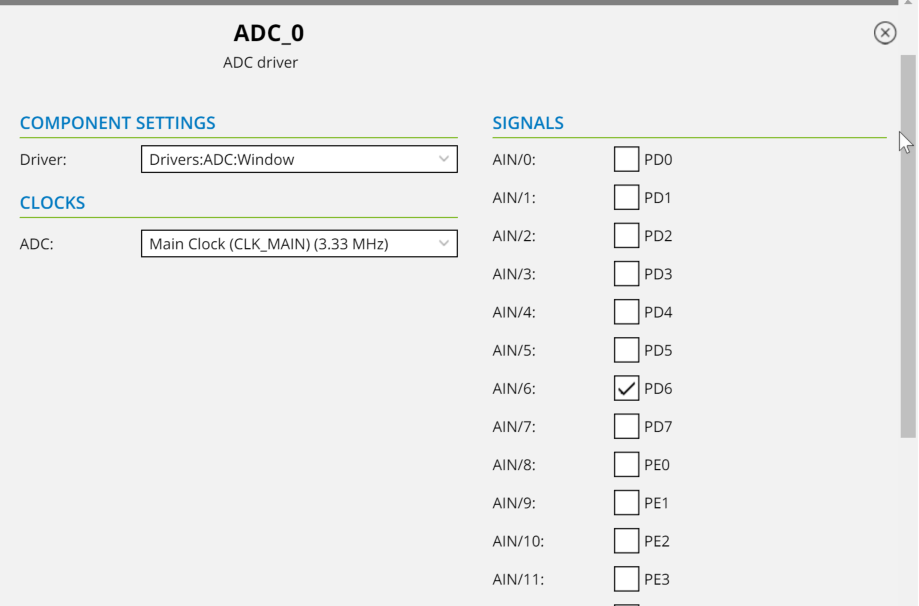
You will see this example uses three blocks, VREF_0, ADC_0, and USART_0. Now let's click "ADC_0" and see which pin is used for.
![]()
In the bottom of window, you will see the current setup for the example program. The PD6 is selected as ADC input. PD6 is "AN" of mikroBUS pinout, and it's ok for the check.
![]()
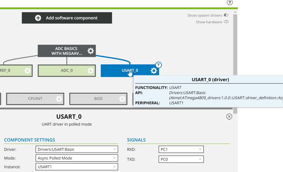
And let's switch to USART_0 setting.
![]()
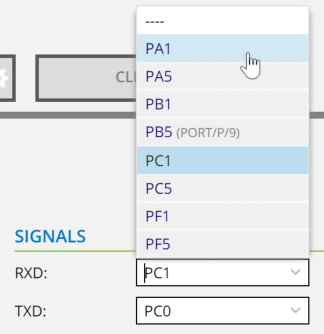
The USB-USART interface (CP2102) of "4809 Explorer board" has a connection with PA0 and PA1 so let's switch to..
![]()
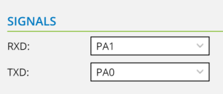
RXD to PA1 and TXD to PA0.
![]()
Now the online preparation is finished. Let's click "Generate Project"!!
![]()
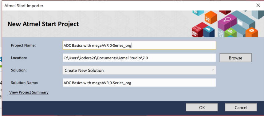
You will see the Atmel start importer windows and please name your new project name as you wish, and after clock "OK" you will see the
![]()
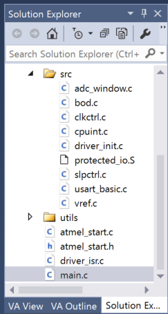
Downloaded files in the solution explorer. The files in src directory are prepared for the definition of above (like USART settings..)
![]()
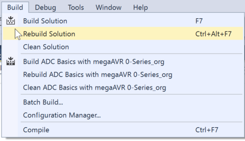
Now the source files are prepared (no need of modification) so let's select "Rebuild Solution"
![]()
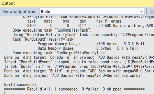
Currently the files are "as is" so it will not produce any error.
![]()
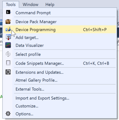
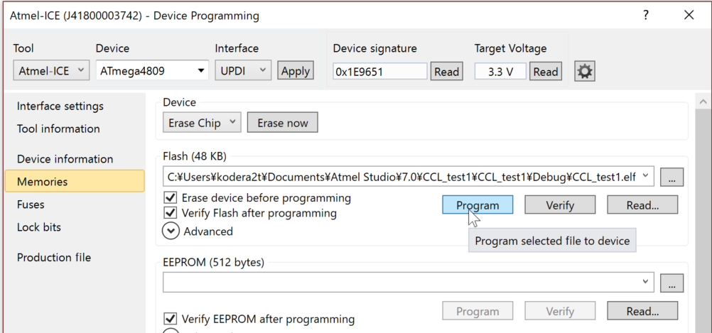
Now let's start binary uploading to the 4809 explorer...
![]()
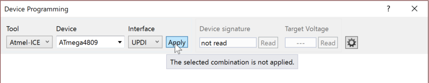
You will see the device programming window, and let's select Tool as "Atmel-ICE" and device "ATmega4809" and select UPDI as interface and click "Apply"
![]()
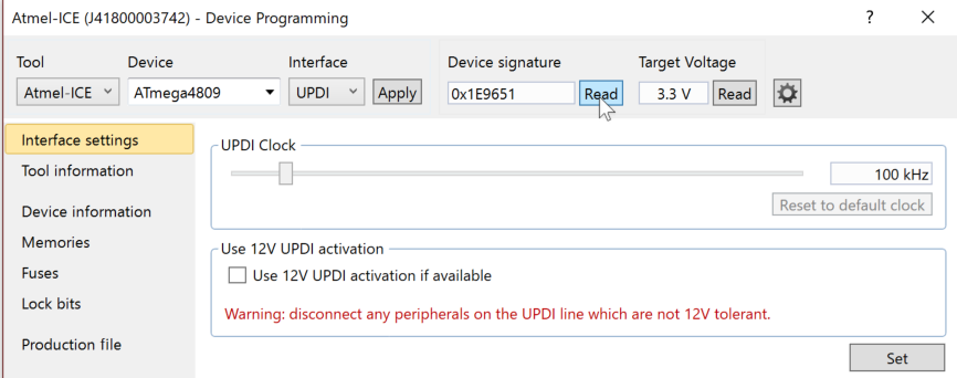
After setting UPDI clock as default 100kHz by click "Set" in the bottom-right button, let's read device signature. If it presents "0x1E9651", then the connection is succeeded.
![]()
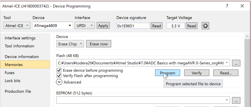
Now the time for uploading. Select "Memories" and just click "Program" will flash your board with the new binary!
![]()
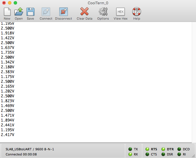
This sample program will read ADC and will output to USART, so just read USART with serial console, you will see the value of PD6(AN) pin voltage of onboard connector.
![]()
In the very the same manner, the sample with OLED display can be made by "ATmega4809 RTOS Example". Let's try!
-
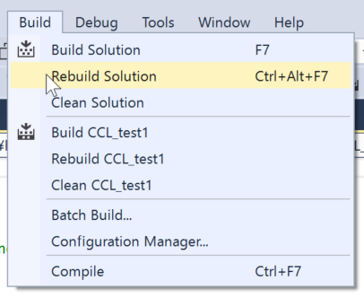
How to start Configurable Custom Logic on ATmega4809
04/19/2018 at 07:24 • 0 commentsNowadays, Atmel is a part of Microchip and some technology is transferred into ATmega chips. (I am not sure which Microchip or Atmel is the original one but..) Configurable Custom Logic (CCL) is one of novelty technique for AVR (PIC's has the name "Configurable Logic Cell", why don't they put same name for same "Microchip"??)
CCL is a kind of tiny programmable logic with look-up-table, same as FPGA or CPLD. Here I would like to show you how to use it through Atmel Studio.
One notice before jumping into the body explanation is,
You don't need to write any code!
Let' get started!!
![]()
Let start on AtmelStudio selecting "Atmel Start Project"
![]()
And click "CREAT NEW PROJECT"
![]()
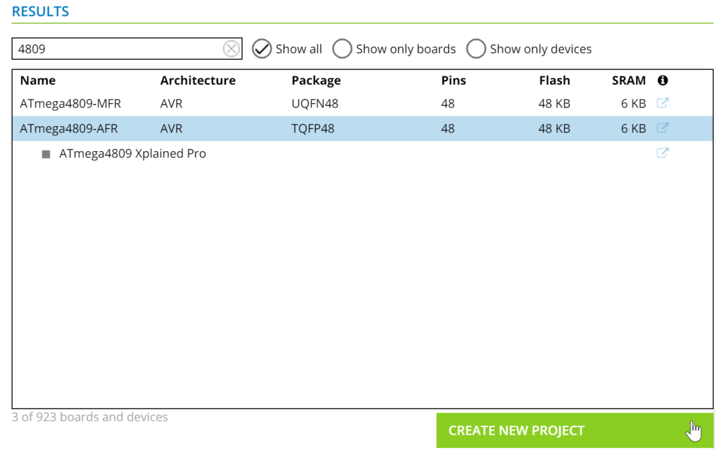
In the window, just put "4809" for search term and select "ATmega4809-AFR" and click "CREATE NEW PROJECT"
![]()
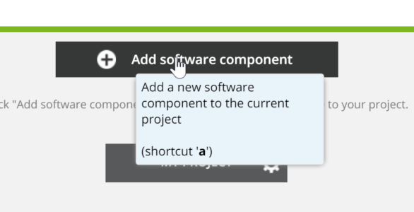
Now the project is fully empty and let click "Add software component"
![]()
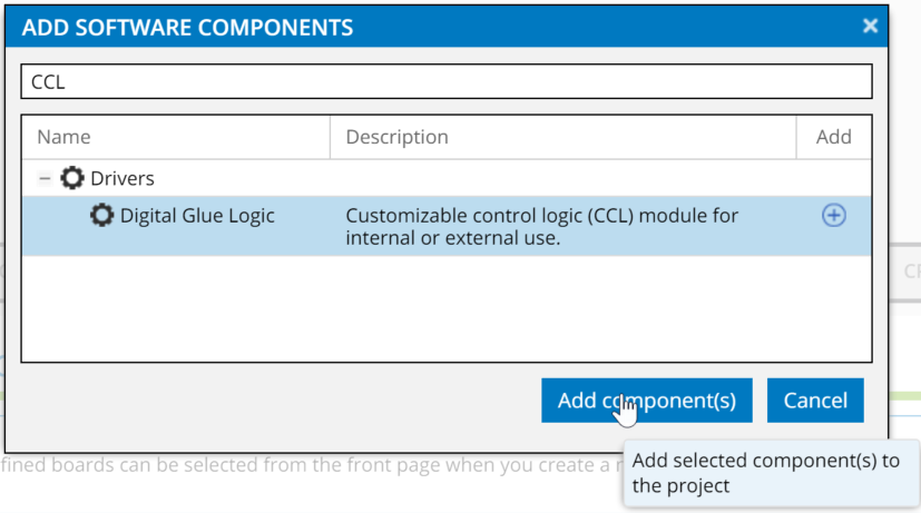
Just input "CCL" for search term and click "Add component(s)"
![]()
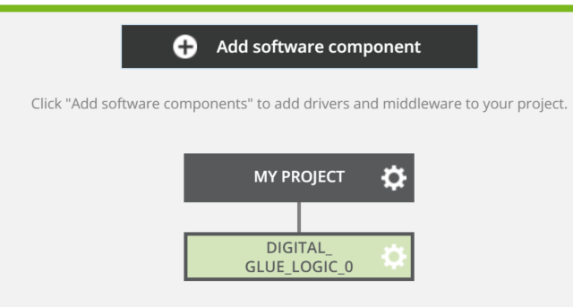
Now your project will grow up with "Digital_Glue_logic_0".
![]()
Let' just click "CCL" on the left side of the window.
![]()
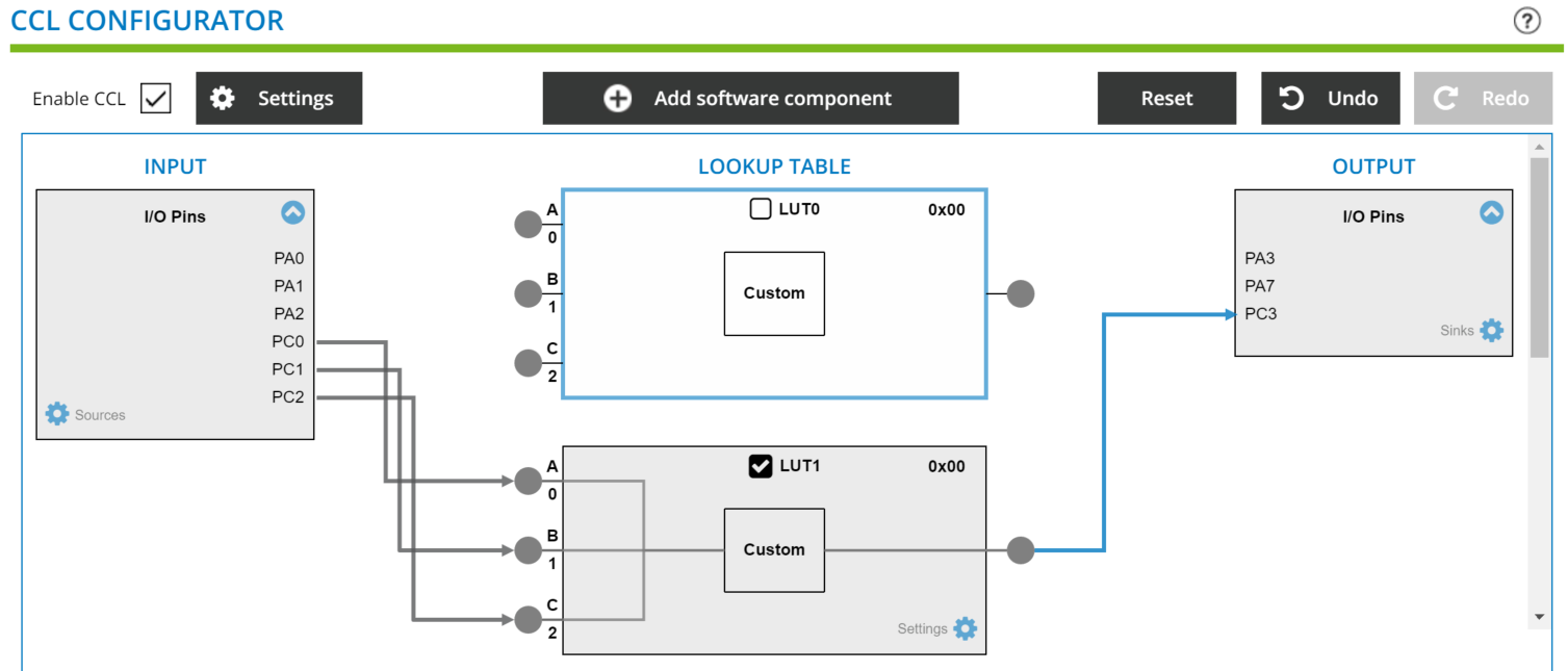
Now the time to connect it. I/O pins of CCL are limited PA0, 1, 2, and PC0, 1, 2. Now the board has accessible pins of PC0, 1, 2 and let make it as input and output as PC3. (You can define as you wish, within the limitation..) Don't forget to activate "LUT1" by check box on.
![]()
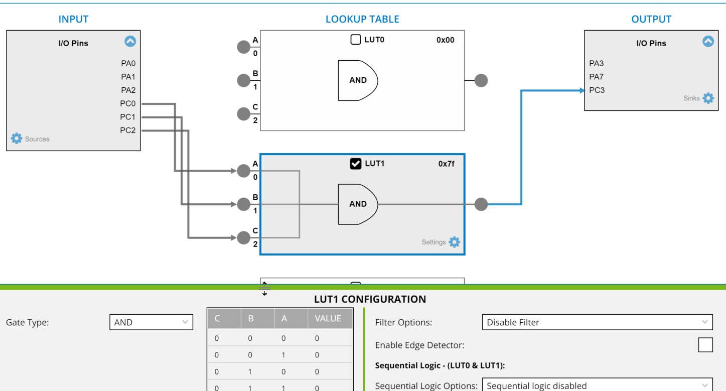
And click and select LUT1 box and make it as simple AND.
![]()
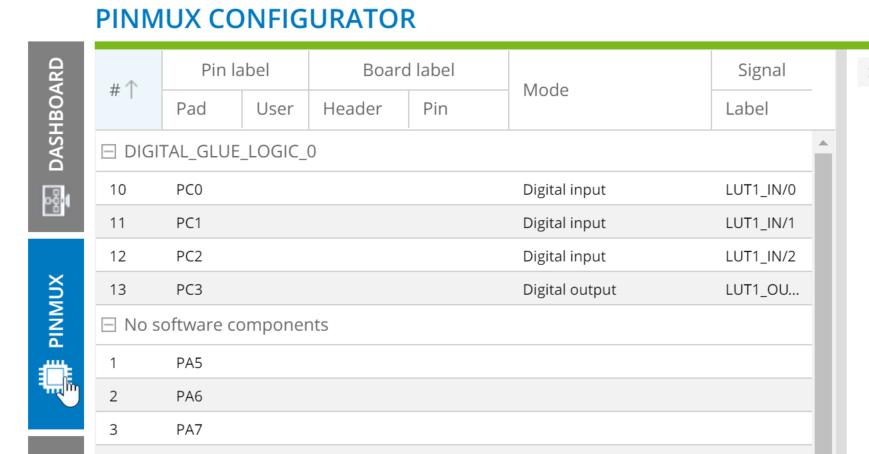
Now let's configure pin status by "PINMUX". Already PC0, 1, 2 are set as input and PC3 as output.
![]()
![]()
Let activate internal pull-up for input and set the initial state of output (PC3) as low.
![]()
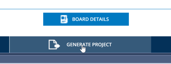
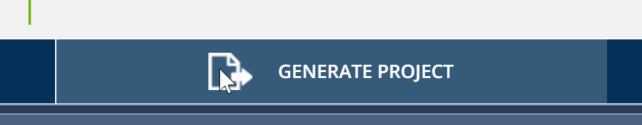
It's done! And let's click "GENERATE PROJECT"
![]()
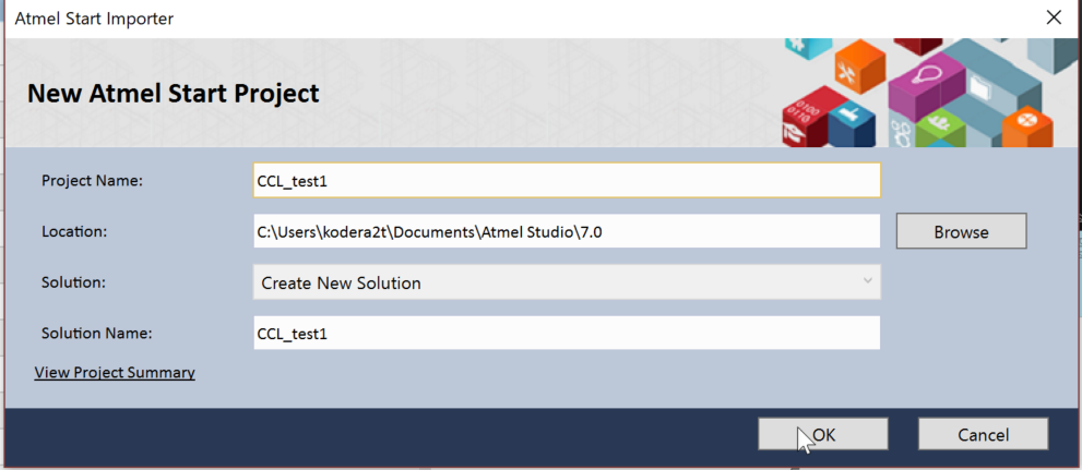
Window will appear and let's name it as you wish.
![]()
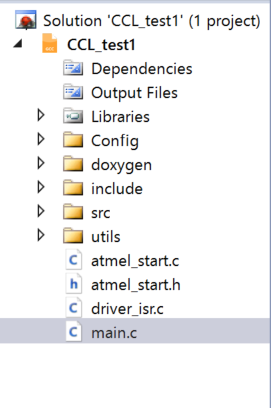
And now all the required source should be set up. Let's check "main.c"
![]()
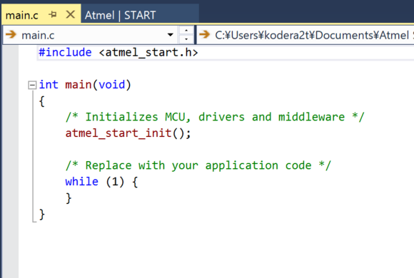
Yes,
It's holy empty!
MCU does nothing for the job. Just initialize MCU, and over.
![]()
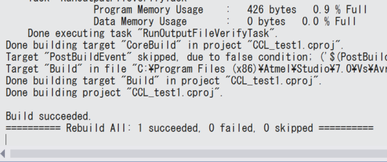
Now, let "rebuild solution"
![]()
Since it is empty, so you sit see "Data Memory Usage" 0bytes!!
![]()
Exactly the same as the general program. Binary can be uploaded through UPDI.
![]()
Now it's done! Switching input level will show the logic level as defined!! ATmega4809 is now working as "single AND"!
-
Short note about "fatal error" on RTOS related project at Atmel Studio
05/05/2018 at 12:04 • 0 commentsSometimes I encountered this type of "fatal error", especially with RTOS project (even if we don't touch this part of code).
![]()
Don't worry, just restarting Atmel Studio and try again, this error will be solved (some bug or I don't know but.).
-
Arduino UNO as UPDI programmer for ATmega4809
05/06/2018 at 02:32 • 1 comment![]()
So I've found, no need of expensive ATmel ICE for programming ATMega4809 UPDI program anymore!!
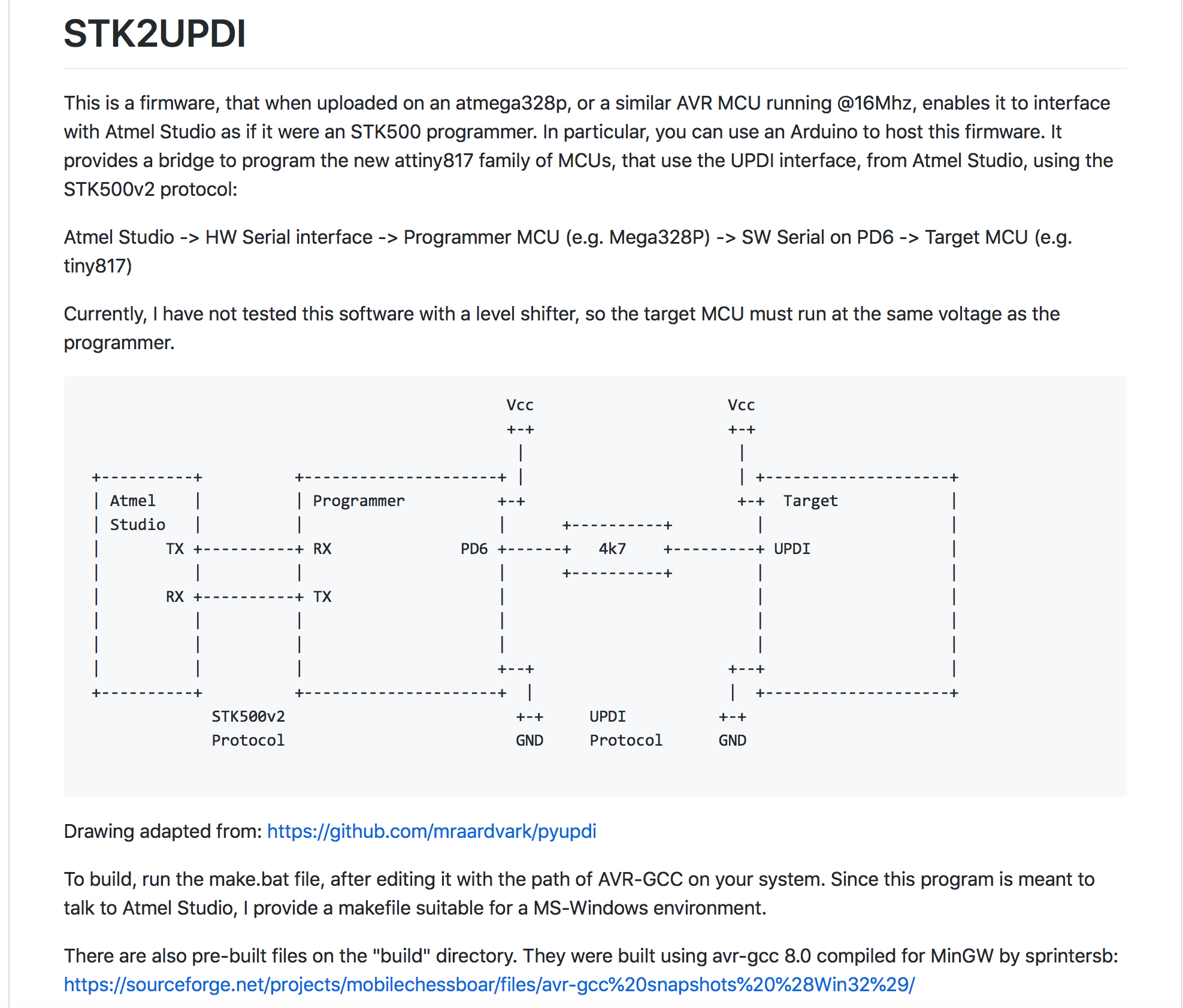
Eltangus already implemented UPDI programmer firmware also compatible with Arduino at GitHub, which indeed makes ATMega328P working as a UPDI speaking STK500!! The procedure to make it is quite easy.
(Step 1) Write UPDI firmware on your Arduino UNO and wiring with ATMega4809 UPDI
![]()
The pre-compiled binary is available at Eltangus's github. You may need Atmel-ICE (or directly from Arduino IDE) and after writing it, your UNO will turns into UPDI programmer. Please don't forget "disable auto RESET" by disabling capacitor connecting from DTR of USB-UART to RST of Mega328P.
![]()
As is written in Eltangus's page, wiring is very simple. Just connecting PD6 (D6 of Arduino pin) and UPDI of ATMega4809 with VCC and GND is enough to complete.
(Step 2) Setting up on ATmel Studio
![]()
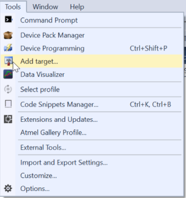
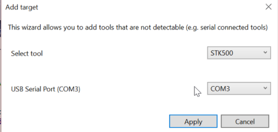
Original state of Atmel Studio will not recognize the existence of "UPDI-STK500 by UNO". Just click "Add target" and
![]()
Select tool as "STK500" and select appropriate serial port on your system. Now almost done!
![]()
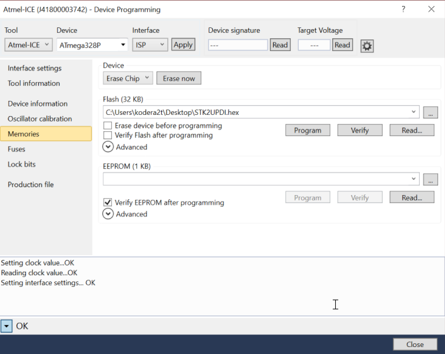
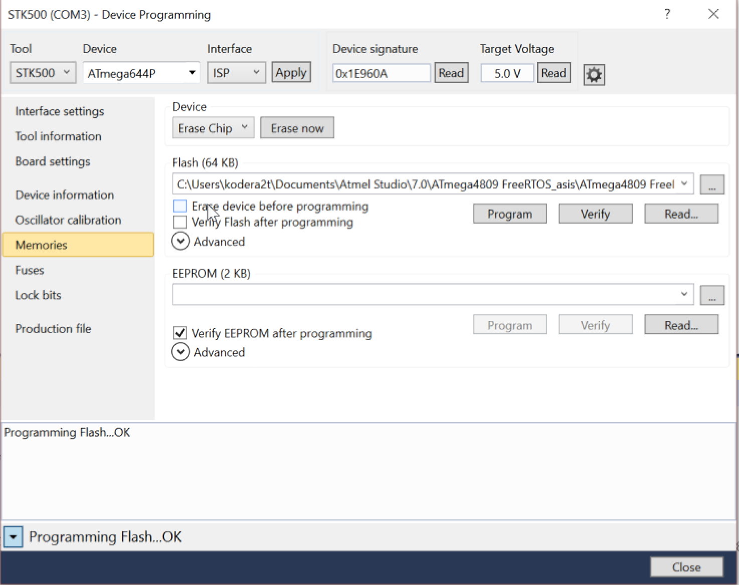
Now the time for programming ATmega4809 through UPDI. STK500 does not know ATmega4809 and just select "ATmega644P" and check off "Erase device before programming" and click "Program".... (Don't need to think too serious, for example interface selection. Just default ISP is enough to complete). As for the implementation, some function is not implemented yet but at least we can write binary through UPDI.
![]()
You will see the binary is uploaded to ATmega4809 !!!
-
Eventually, programmer is embedded, no need Atmel ICE anymore!
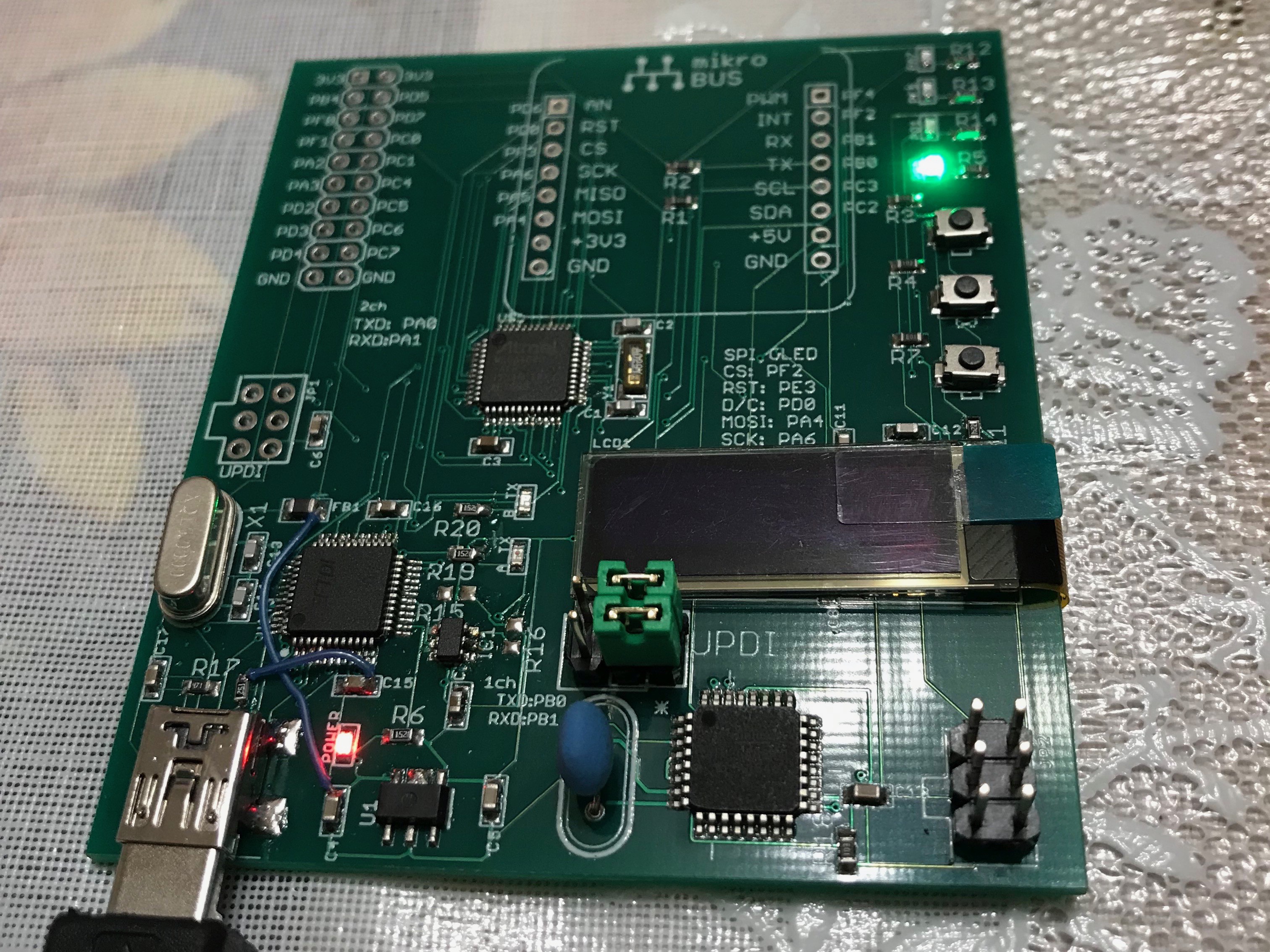
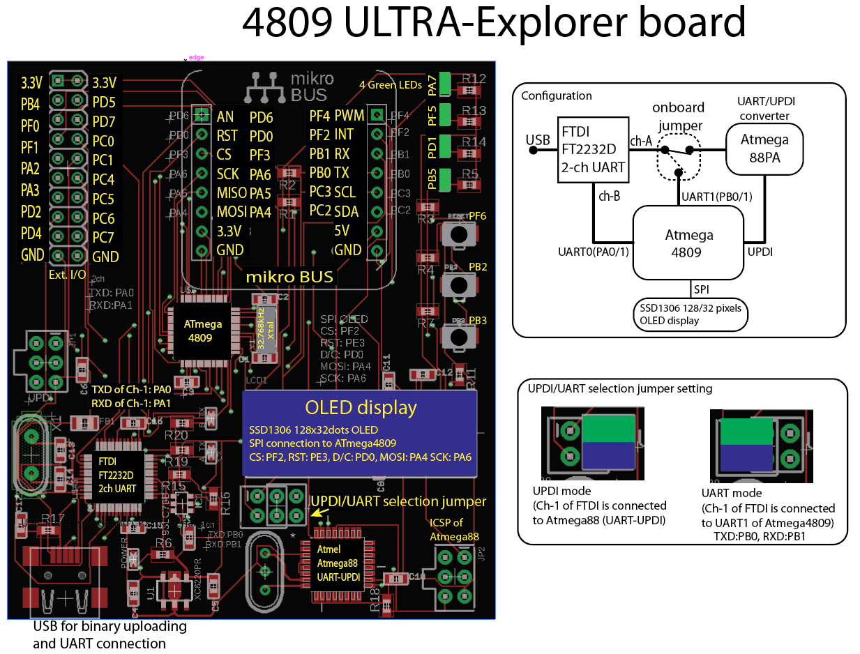
05/12/2018 at 13:03 • 0 commentsEventually, my board becomes a "independent board".
![]()
It consists of
- FTDI FT2232D Dual USB-UART interface.
- Atmega88PA, working as jtag-UPDI interface
- Atmega4809 , the main MCU
- OLED display connected through SPI to Atmega4809
Not always FT2232D-Atmega88PA connection is not necessary, and its connection can be selected ATmega88PA or UART1 of Atmega4809. The other UART of FT2232D is always connected to UART0 of Atmega4809.
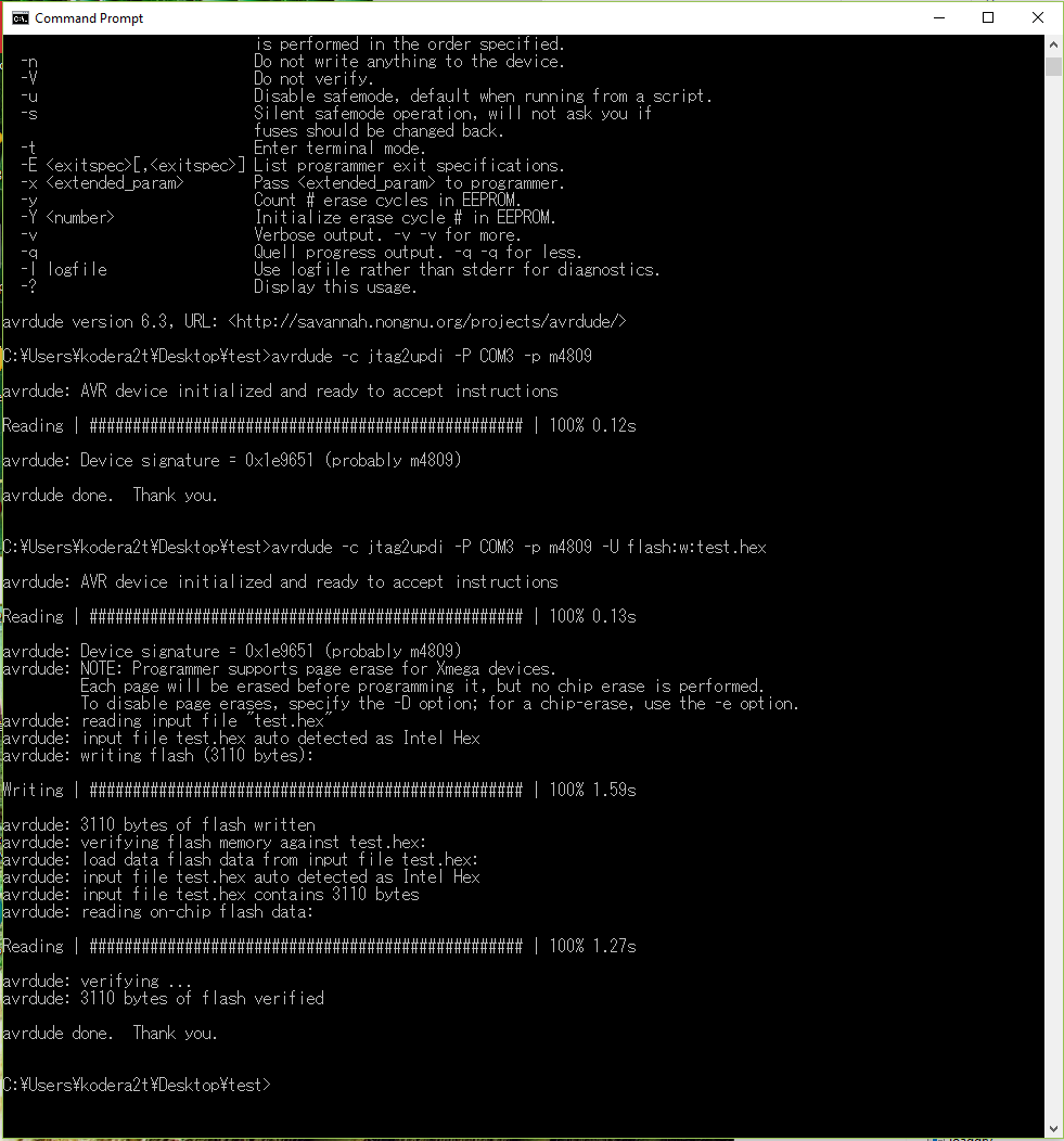
By the proper jumper setting, one of UART of FT2232D is connected to Atmega88PA and direct binary upload is enabled by avrdude as follows:
![]()
This implementation of jtagupdi is made by ElTangas, the same author as STK500 UPDI interface implementation. By the sake of this great implementation, now it's very close to be "Arduino-like" board. Currently binary is made by Atmel ICE and .hex file is uploaded by avrdude. The modified avrdude.conf is also included in the ElTangas's GitHub.
-
Demonstration of binary uploading through avrdude to Atmega4809
05/13/2018 at 03:21 • 0 commentsHere you can see the demonstration movie of binary uploading of my board!
The .hex file uploading command is
avrdude -c jtag2updi -P COM# -p m4809 -U flash:w:name.hex
, where COM# is the port number of your system and name.hex is the name of the binary. It's very handy now!
-
More details about the current board form..
05/13/2018 at 11:59 • 0 comments![]()
Here is a bit more details about the latest board...
-
Blinky test on ULTRA 4809 Explorer
05/22/2018 at 06:09 • 0 comments![]()
As presented, now the ULTRA 4809 Explorer is available at tindie. By the UART-UPDI function with avrdude, LED blinky test is super-easy! Here I would explain how to.
Before starting, you will need to install
- Atmel Studio (latest one)
and
- Arduino IDE
Arduino IDE should be installed in order to get avrdude.
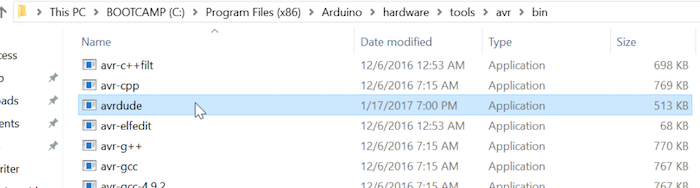
![]()
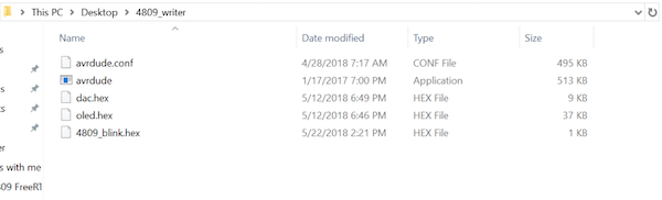
First of all, please find "avrdude" in Arduino IDE and copy it (not move it, otherwise Arduino IDE will not work anymore) to some working directory. (in this case, I made it on desktop named "4809writer".
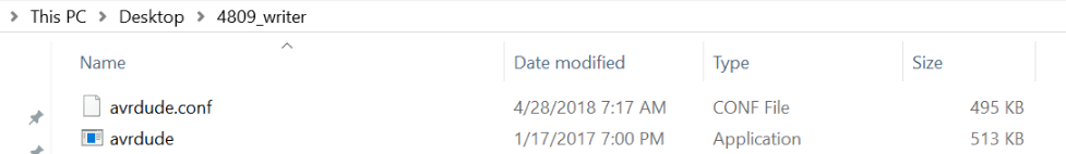
![]()
In the working directory, we also need "avrdude.conf", which is available at ELTangas's jtag2updi repository.
![]()
Now let's start new project at Atmel Studio..!
![]()
And simply select GCC C executable and name it some wonderful name (in this case, simply 4809_blink..)
![]()
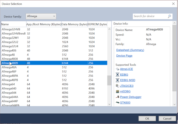
, and select proper device, YES ATmega4809 !! (if not appears, your Atmel Studio is older version. Please update to the latest one.)
![]()
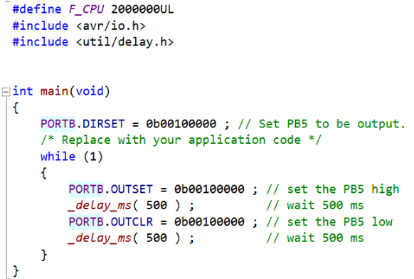
And Let's write short program for PB5 LED blink. The notation is the same as Xmega.
![]()
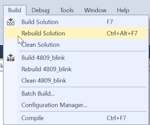
And select "Rebuild Solution"
![]()
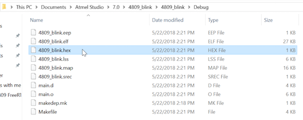
If compile and link are succeeded, .hex file will be produced in the project/Debug directory. Just copy the hex file to your working directory (containing avrdude).
![]()
As you see, please put your hex file init (where dac.hex and oled.hex are different project ones, please ignore it.)
![]()
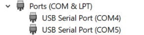
Now please connect USB cable between your ULTRA 4809 Explorer board and computer, then check system recognition at device manager. This special board has 2ch UART and smaller number port (in this case, COM4) is connected to UPDI converter.
![]()
Now the time to binary uploading. Just command it, the LED connected to PB5 will blink as you wish
![]()
ATMega4809 developing board project
Very new chip by Microchip(Atmel) ATmega4809 has a very unique CPLD like logic and also promised to be applied to next Arduino, why not try!