 fadilluquman
The project basically consists of the following components:
1) The brain, RaspberryPi Zero
The brain of the project is a RaspberryPi Zero. With its cost of just $5, it is an amazing processor and perfect for our application. It not only cuts our cost but also helps in avoiding an overkill of processor found in its elder brothers the RaspberryPi 1, 2 or 3.
The Pi Zero is configured to act as a Samba Server. The Samba Server provides the baseline for basic file transfers. This protocol is very convenient to use for our application as the user would be interested in reading a normal pendrive on-the-go or backing up his data from his smartfone on a pen drive, where does not have laptop access, just form the device.
2) The Comms, Wi-Fi/GSM module
Unlike Raspberry Pi 3, the PiZero doesn’t have a Wi-Fi module of it’s own. To equip the device with wireless capabilities, we shall use a normal 802.11 adapter. But instead of using 2 separate devices for wireless communications and a GSM gateway, we can use a normal Wi-Fi equipped unlocked dongle with interchangeable SIM cards. The advantage of having such a single Wi-Fi dongle is that we can relieve from the headache of routing the data packets from the GSM module to Wi-Fi which would be unnecessary overhead on the PiZero. Also, these dongles would have DCHP stacks which dynamically provide IPs, coordinate data packets and route it to Wi-Fi. The dongle is connected to the one of the four downstream ports of the hub internally.
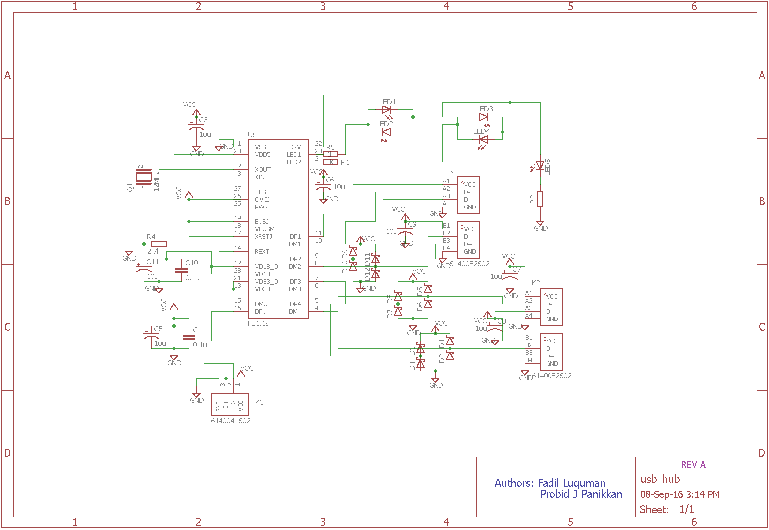
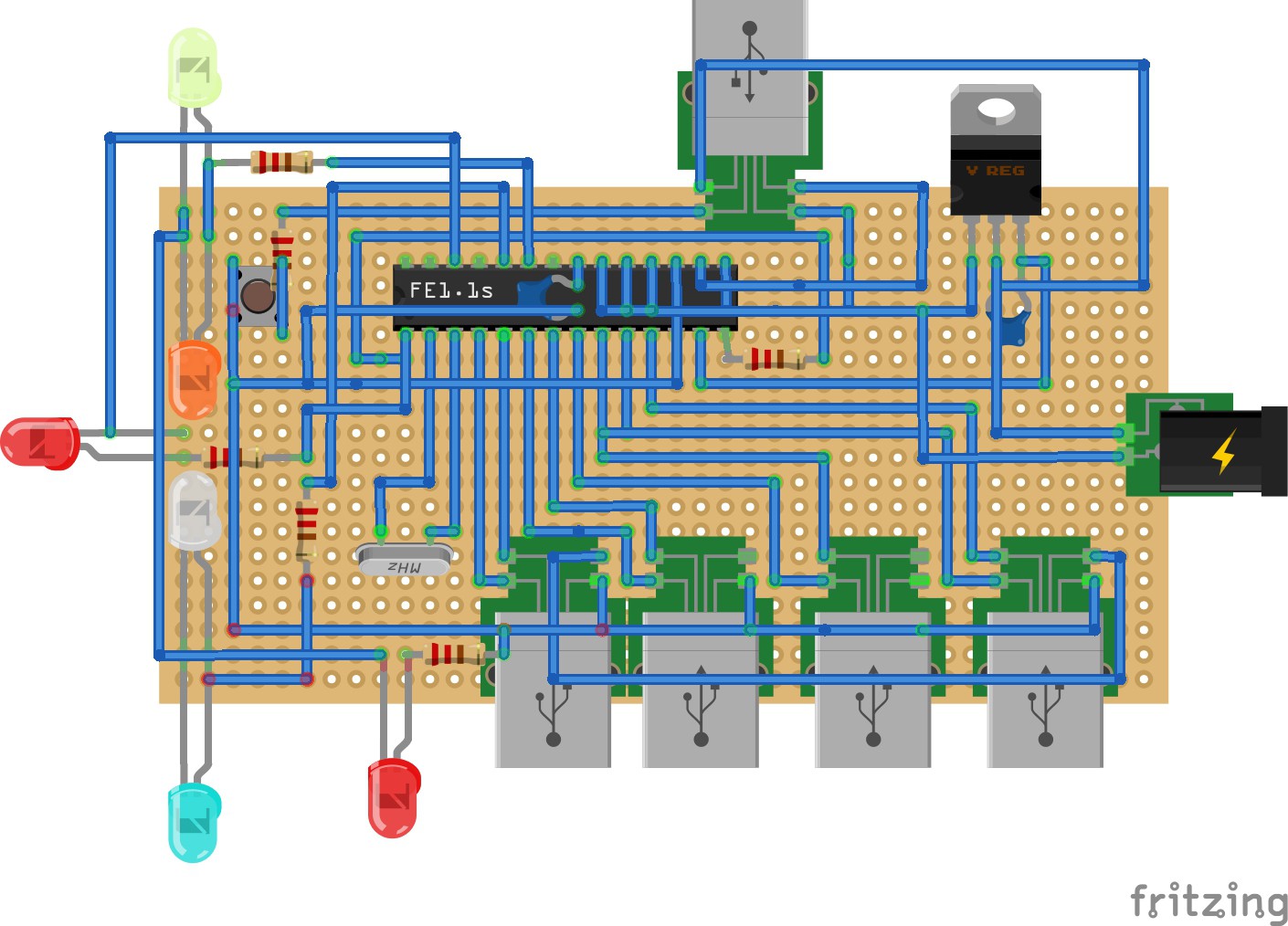
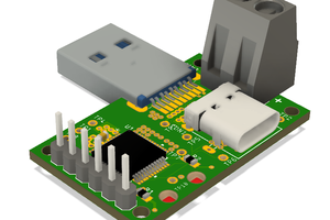
3) The enhancer, USB Hub
The non-availability of more USB ports on the PiZero doesn’t limit its capabilities. Simply attaching a USB 2.0 Hub would easily work around the problem. Such a 4 port USB hub is designed for the device with minor modifications under the courtesy of Pi Angle Zero by Sean Hodgins. The hub’s upstream port is connected to the Upstream port of the PiZero.
4) The memory, Pen Drive
A completely body-stripped pen drive is connected to USB hub internally. Any normal pen drive would suffice but let’s stick to 16GB for time being. Furthermore, for memory back up or instant data access from a normal pen drive, without wireless access from a smartphone, the user can hook it up to the 2 external USB 2.0 ports provided.
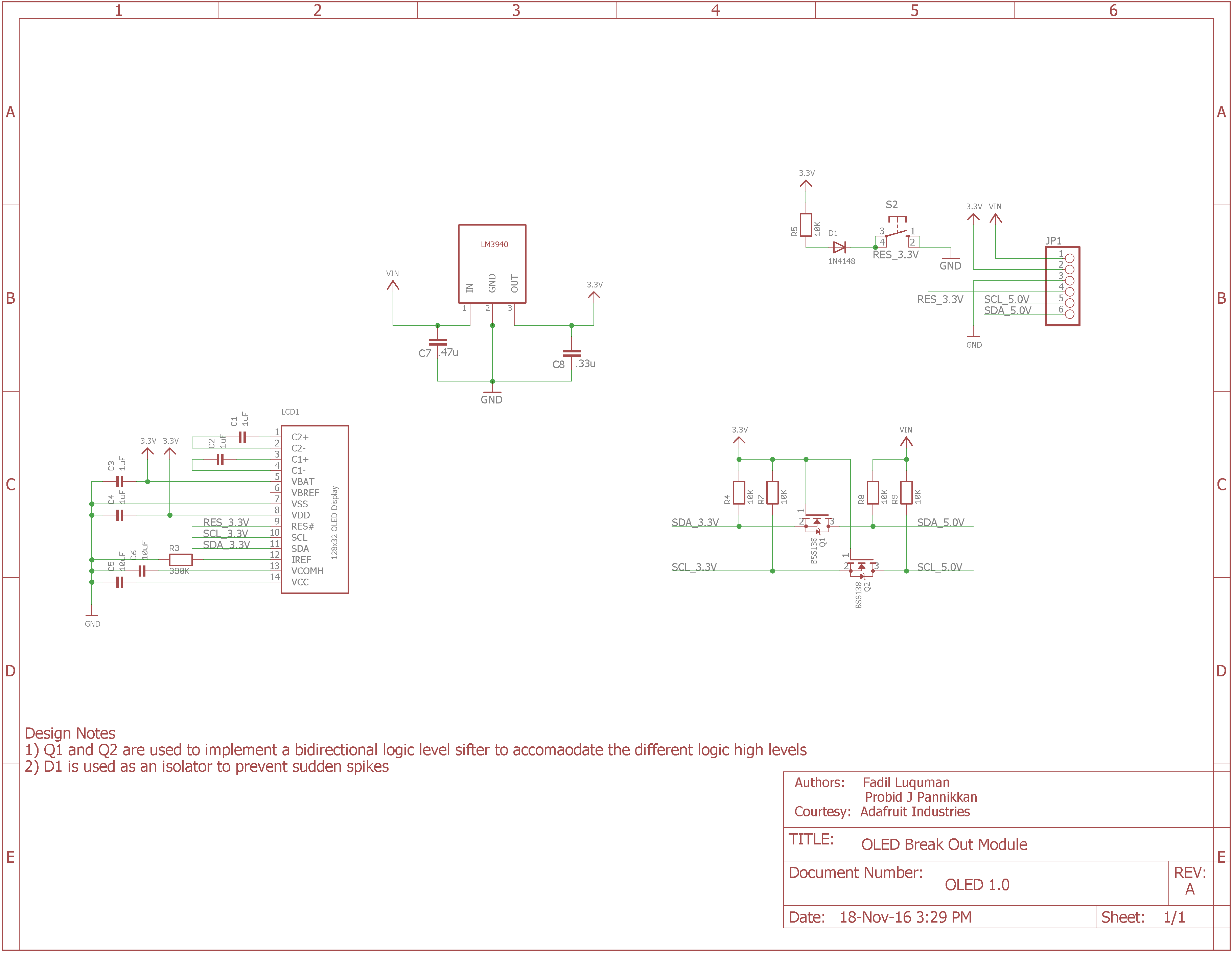
5) The Display, Oled
Oled displays are being common these days due to its extremely low power consumption. These kind of displays are ideal for mobile devices. It displays the basic information such as battery percentage, signal strength, Wi-Fi signal strength etc. These kind of displays are accessed via I2C or SPI such as the 128x32 Oled Display from Adafruit.
 Jakob Faltisek
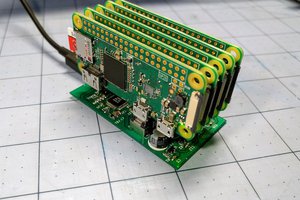
 ajlitt
 ACROBOTIC Industries