-
1Step 1
Step 1: Motherboard Assembly and Programming
![]()
I designed all of the boards to be hand solder friendly, with leadless QFNs all on one side (that can be reflowed). If the other side has components, these are usually larger and easier to hand solder.
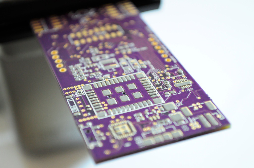
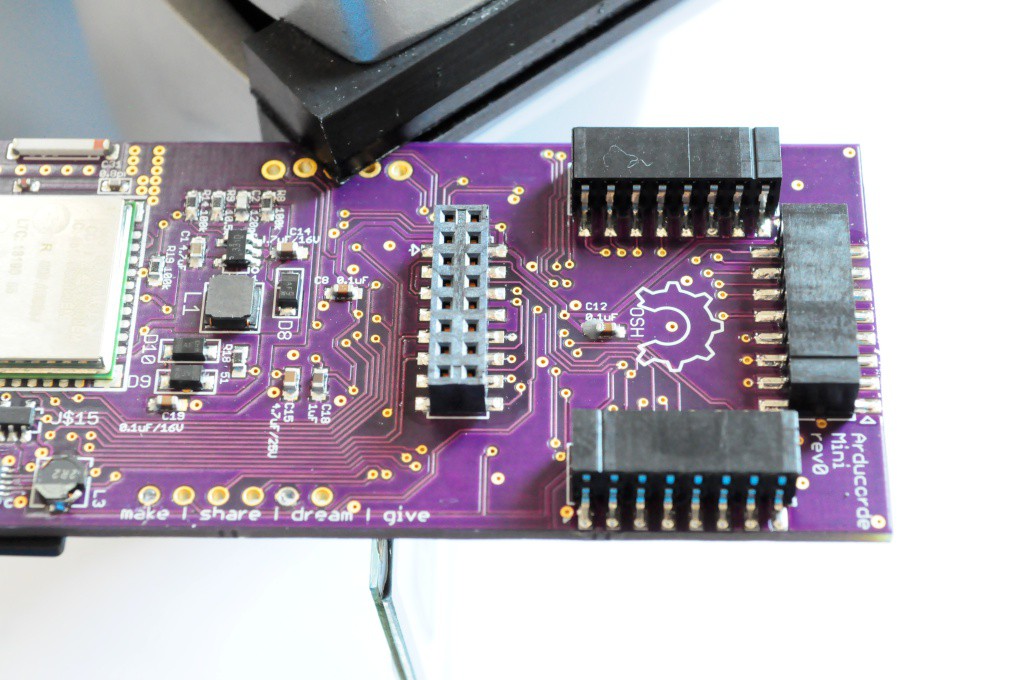
Step 1 is to use your stencil to apply paste to the CC3000 side of the motherboard. Note that we'll occasionally switch between Revision 0 and Revision 1 motherboard pictures, but you should be using revision 1 (or the latest release, if a later revision exists at the time of reading).
![]()
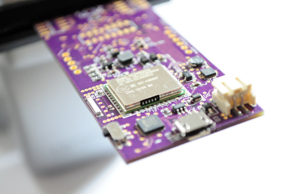
Populate the back components. I recommend leaving off the sensor headers until the end -- it'll make it easier for the board to fit into a holder while you solder the top components later.
![]()
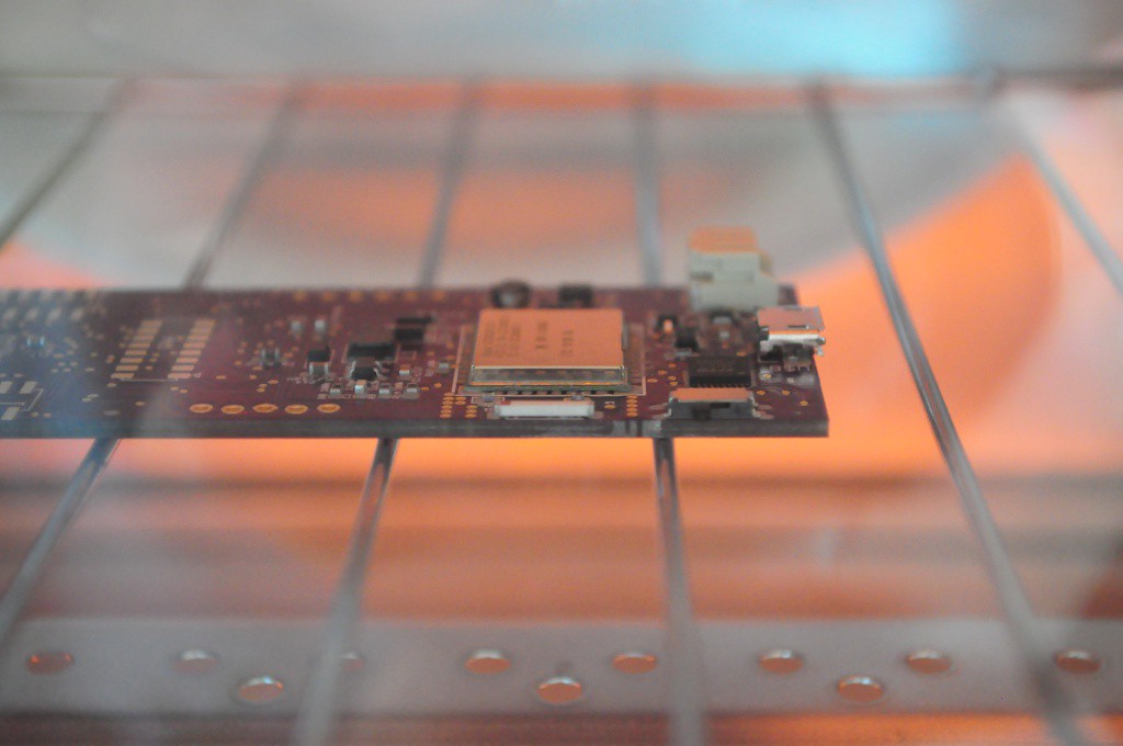
Reflow the bottom side. You may wish to pre-solder at least the mechanical mount points on the USB connector and battery connector to make sure they don't move (and end up angled) during reflow.
![]()
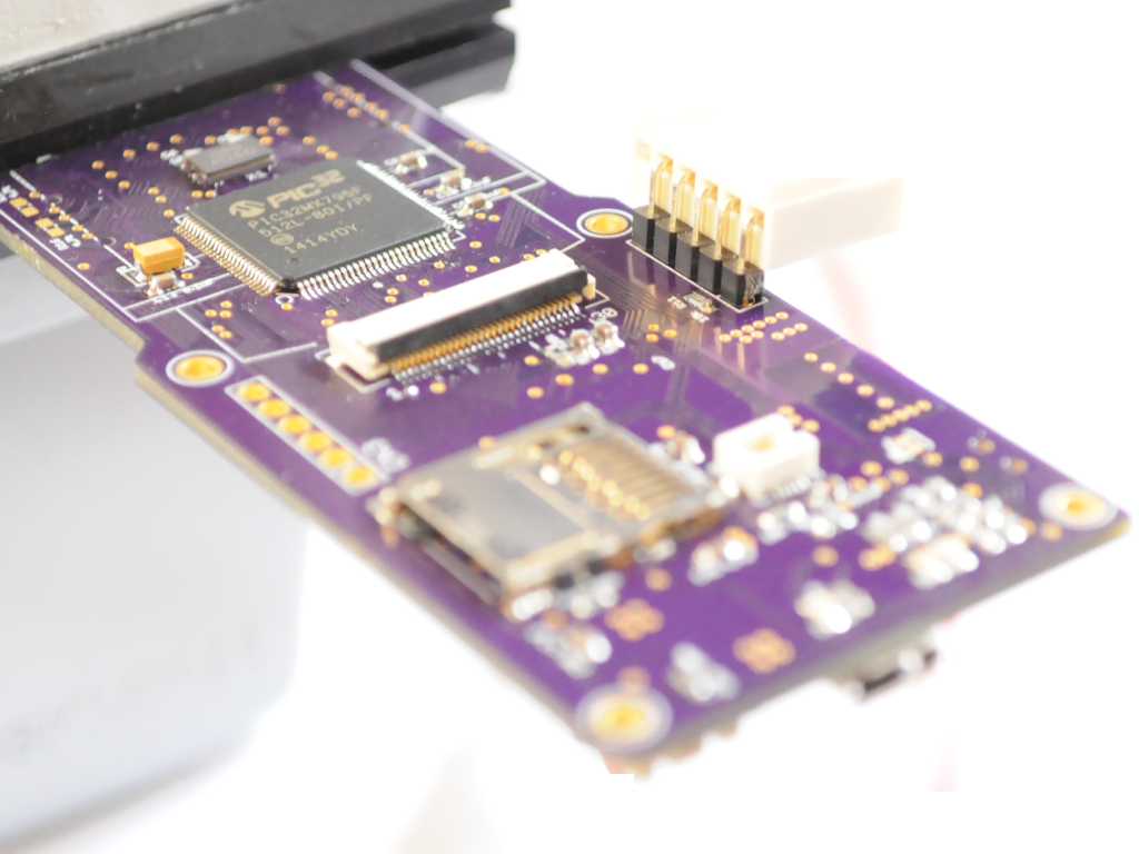
Next, solder the top components. I do this by hand, starting with the PIC32, moving to the OLED connector, and then if everything looks good, stenciling the bottom of the board for the passives. Please take your time, it's not a race -- and if you bridge the connections it will make a mess of the board to clean up. For reference it takes me about an hour to solder all four sides of the PIC32, going slowly with very small amounts of solder paste. The OLED connector is similarly fine pitched, and the capacitive touch wheel connector is VERY fine pitched, so take it slow. The crystal will require a quick reflow with a hot air station to be properly hand soldered.
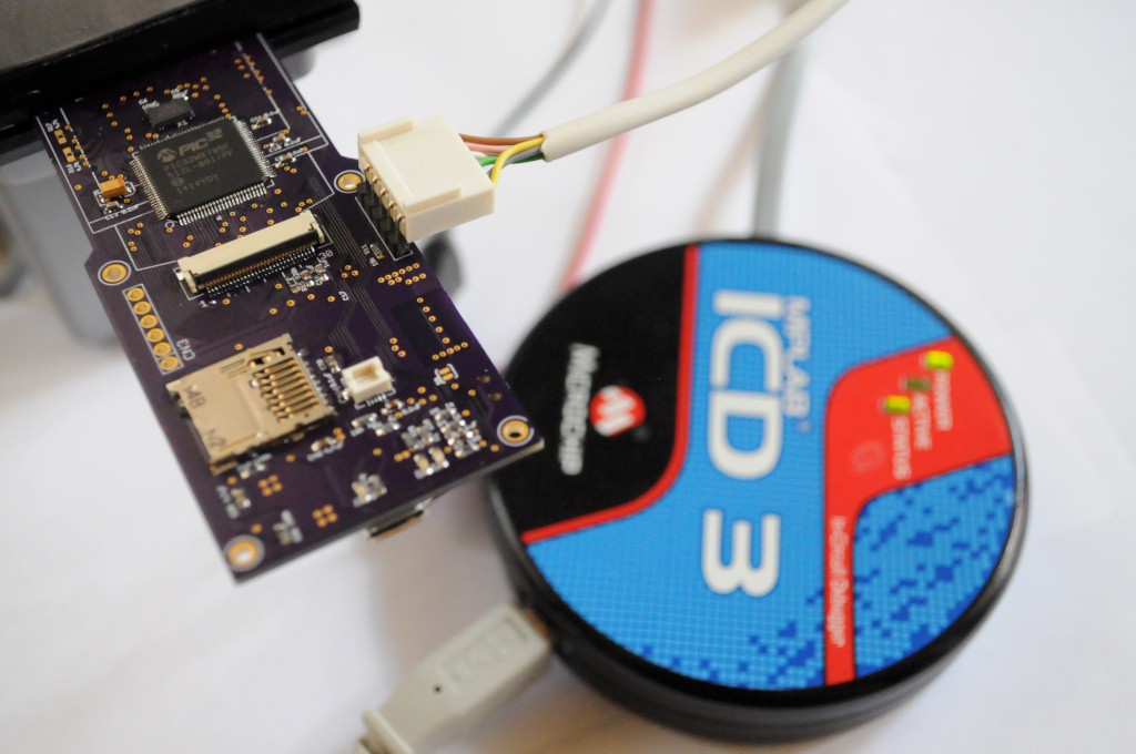
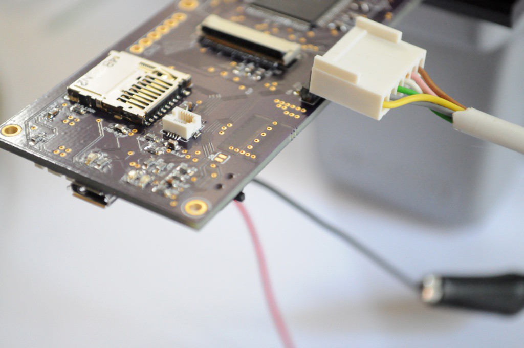
Do not solder on the programming (ICD3) connector -- This is a one-time use connector, so the pins are offset such that the tension will let you quickly program the device, then remove the header so it's not in the way.
![]()
Firmware
Next we'll need to load the Chipkit bootloader onto the Arducorder Mini motherboard using a Microchip PIC programmer, like this ICD3. If you're not a PIC developer and don't need the debugger functionality, Microchip also has a programmer that's about a tenth of the cost, and here we're just using it to upload the bootloader -- afterwards we'll be uploading firmware using the Chipkit IDE over USB.
![]()
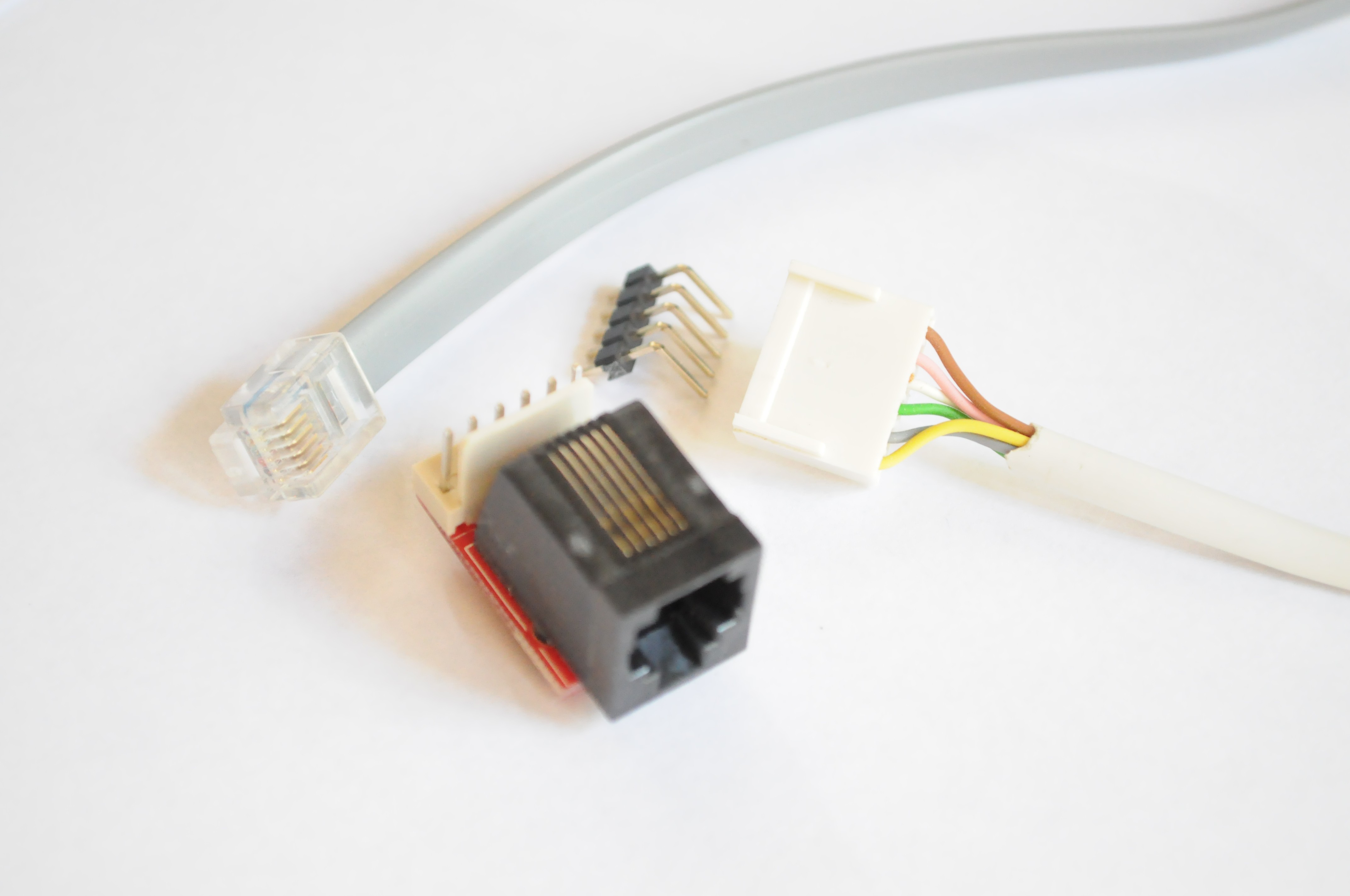
If you're using the ICD3, you'll need a converter to go from the 6-pin phone connector to a regular 0.1" header (Sparkfun sells these). Note that only 5 pins are exposed on the motherboard -- the unused pin (opposite of MCLR) isn't included since space is at a premium.
Don't forget to power the board from an external supply through the battery connector -- 3.3V from a regulated supply should to well. Ensure that you check for bridges before powering the board, and are using a power supply with a fuse and current meter so that it doesn't blow the whole thing to the moon if you've got a solder bridge.
![]()
The Chipkit folks maintain a great set of documents on how to go about this process (which only takes a few minutes), as well as having the bootloader that you'll need to install:
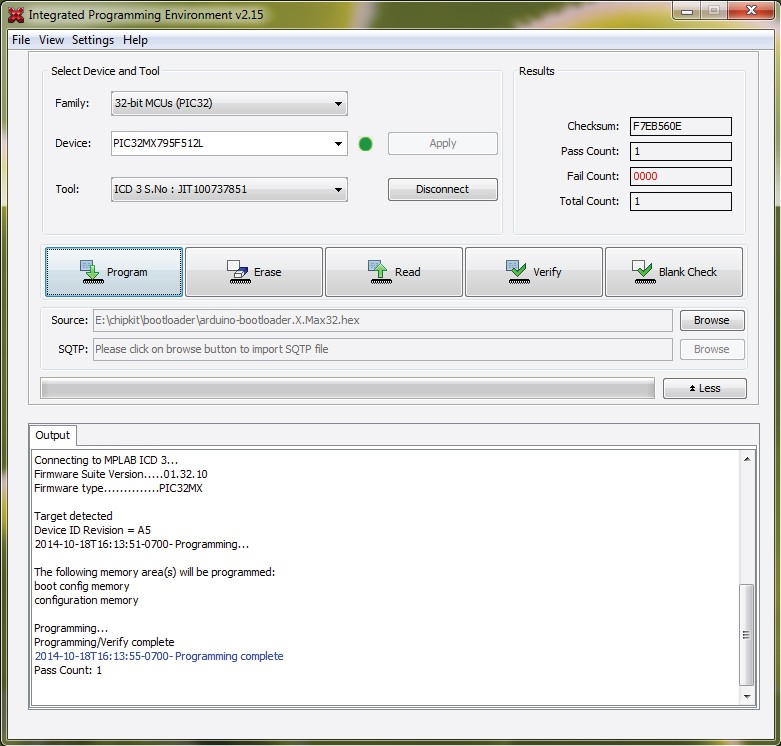
The abridged version is that in the new Microchip IDE this has been made super easy, and takes only a few clicks with their HEX programmer:
![]()
Connect, Select bootloader, Program. If you see something like this output, then congratulations, the programmer can successfully commuicate with the PIC32 and has programmed the bootloader! If you don't see 'Target Detected', ensure that you've powered the board externally, and that the power switch is in the "ON" position. If those are the case, verify your soldering.
CC3000 Firmware Update
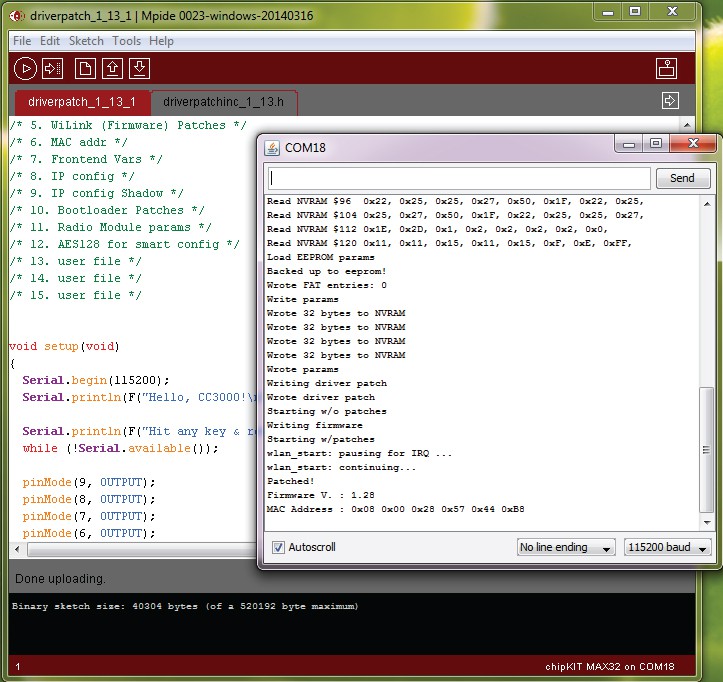
The Adafruit CC3000 library requires that the firmware on the CC3000 is updated in order to connect. This is a quick update and a good first test. Unconnect the programmer and connect a USB cable. Using the Chipkit IDE (Ideally version 0024 or later), load the driver patch sketch and allow it to update the CC3000 module firmware. You shouldn't require the Arducorder-modified Chipkit IDE (which updates a few of the libraries for better Arduino 1.x compatibility) for this operation.
![]()
Finishing up soldering
Now that everything's working, feel free to solder on the sensor board connectors:
![]()
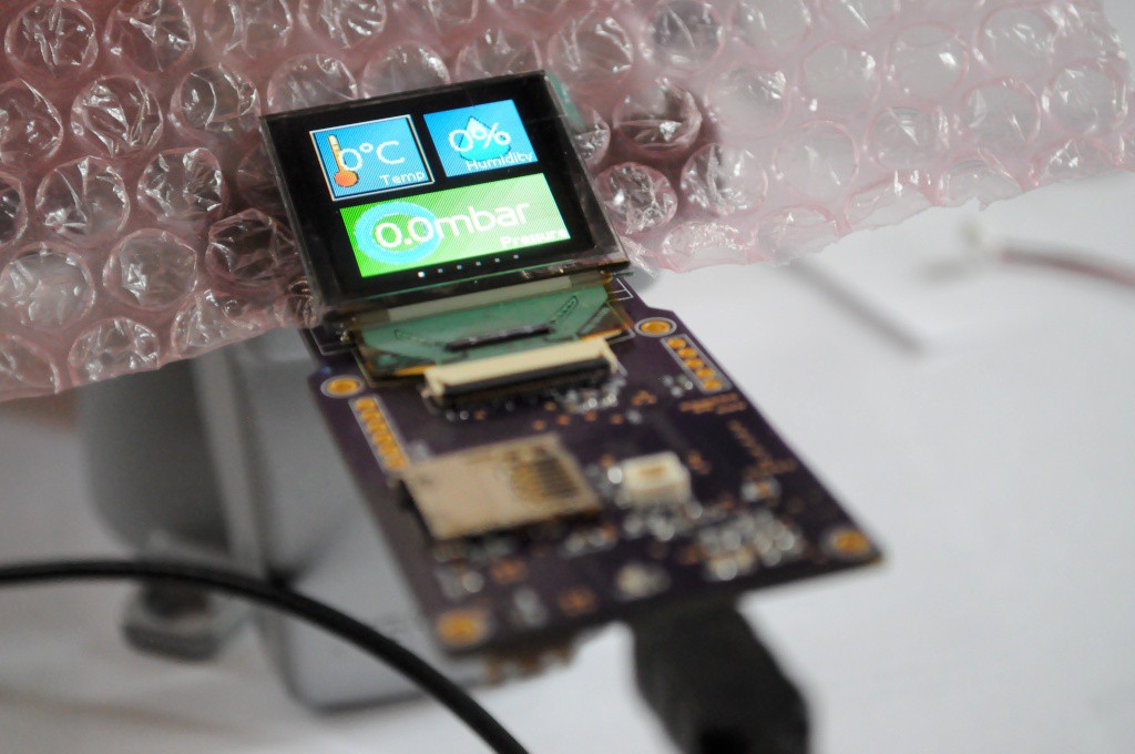
If you're eager to see /something/ on the screen, you can grab the latest Arducorder firmware (currently "test2k") as well as the updated Chipkit IDE (skip ahead to the main firmware step for the link). You will likely see something on the screen before it fails to find the sensor boards or capacitive touch wheel attached, and freezes -- but this will let you know that the screen is healthy and functioning.
![]()
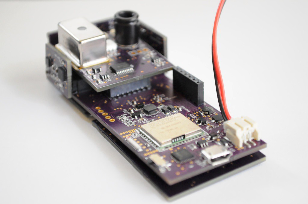
Congratulations! You now have a working Arducorder Mini motherboard! On to building the sensor boards.
-
2Step 2
Step 2: Sensor Boards
![]()
Congratulations -- if you've successfully soldered the motherboard, then you'll likely have little issue putting together the sensor boards. They're very tiny, and about a 2 hour build per board. Because the process is similar for each board, here we'll just highlight any deviations to keep in mind. All of these boards have been designed to be relatively easy for an experienced surface mount solderer to put together -- one side has most of the parts and can be easily reflowed, and then the other side (usually just a connector, and perhaps a few passives) can be quickly hand soldered.
The six sensor boards are: (1) the capacitive touch board, (2) the magnetometer/IMU board, (3) the atmospheric board, (4) the lightning sensor board, (5) the spectrometer/thermal camera board, and (6) the radiation sensor board. Of these, only the spectrometer board and radiation sensor board have special instructions.
Spectrometer Board
![]()
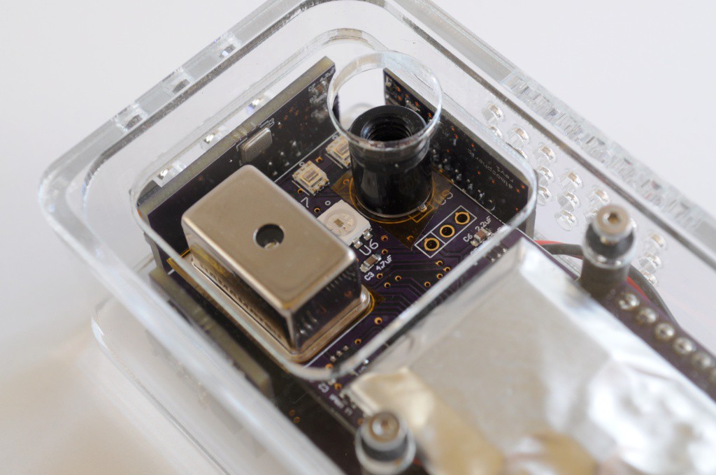
The spectrometer/thermal camera board houses the most high value sensors on the entire device, and individually represents most of the BOM. Ensure that you take care when assembling this board, and verify the voltages (both 3.3V and the 5V boost for the Hamamatsu micro spectrometer) before soldering the thermal camera and spectrometer.
![]()
I very strongly recommend placing squares of kapton tape (or another non-conductive tape) under both the spectrometer and thermal camera before soldering. Their cans are conductive, and this will help avoid any of the other pins accidentally bridging with the case.
Optional light source header: The spectometer board includes an optional 3 pin header for connecting your own light source. This header exposes 3.3v, GND, and an I/O pin. It's recommended that you solder a connector to this header, that you can attach LED boards to. The I/O pin should be used to drive a MOSFET that powers the LED -- the pin itself shouldn't be used to source any current (especially for something like a small incandescent bulb!)
Filters: The two light sensors at the top right of the board have mount holes on either side. These are designed to allow user-configurable narrow band filters (or polarization filters) to attach, for user configurted applications. You'll need to laser cut or 3D print a tiny holder for your filters that affixes to this footprint, with M2 machine screws.
Radiation Sensor Board
![]()
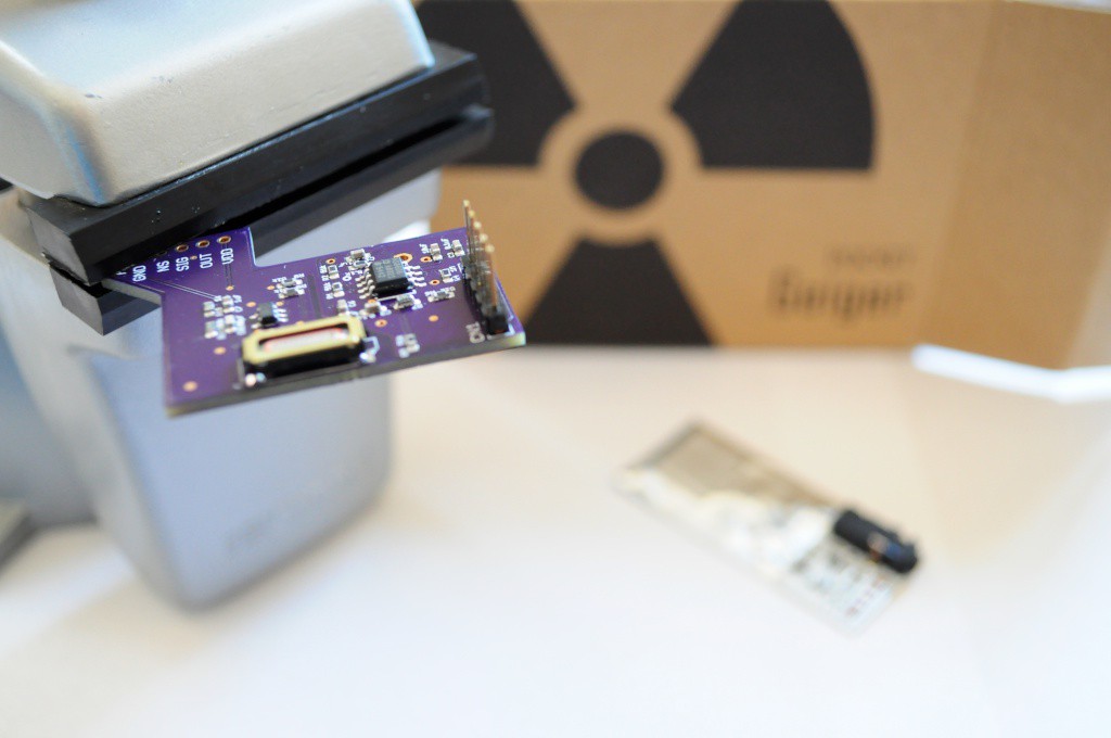
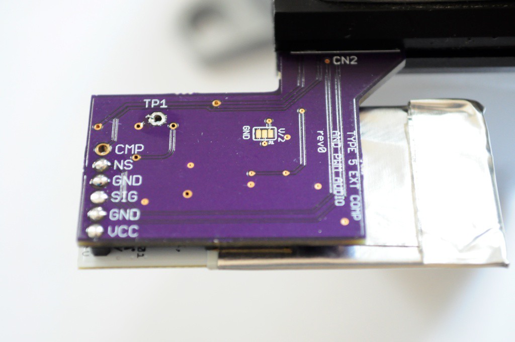
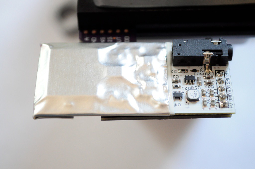
The radiation backpack board allows the Radiation Watch Type 5 connector to the Arducorder Mini. This sensor board also contains an external comparator that allows the radiation sensor to be much more sensitive. You can experiment with different values for the calibration resistor, but a 2.7k 1% seems to have a good balance of signal-to-noise for me.
![]()
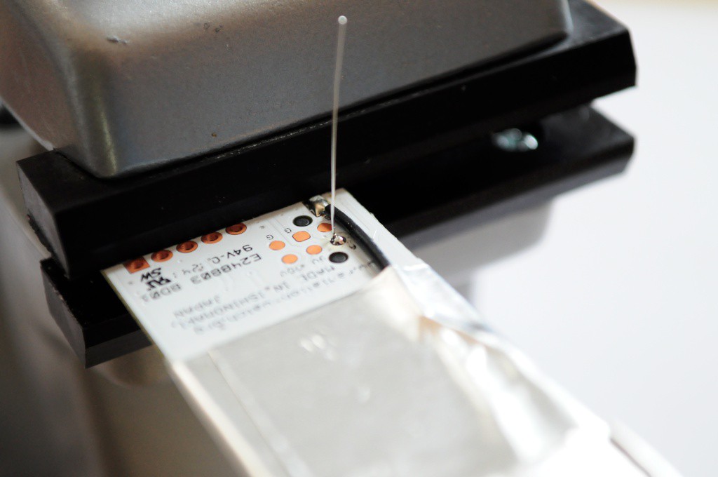
In order to make the Type 5 extra sensitive, you will have to solder a piece of wire wrap to one of the test points. I recommend making a tiny loop at the end (with some tweezers), bending it 90 degrees, then hitting it with some solder paste. This connection has a very low voltage signal running through it, so be sure to do a good job soldering.
![]()
The short piece of wire wrap solders to the backpack at TP1, which should be directly above the appropriate location on the Type 5.
![]()
Congratulations! Feel free to connect this board up to an Arduino/Chipkit to test it out separately with the example firmware before continuing, if you'd like. The folks at Radiation Watch also have some Arduino-compatible Type 5 firmware that should work with this board (and takes the noise pin into account, if you're planning on vibrating the sensor).
Cat in Digikey box interlude
![]()
Magnetometer/IMU Board
![]()
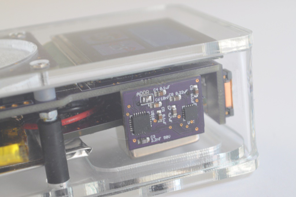
This board includes an I2C address solder junction for the MPU9050. Ensure that it's shorted as above (otherwise it may conflict with the MPR121).
Atmospheric Board
![]()
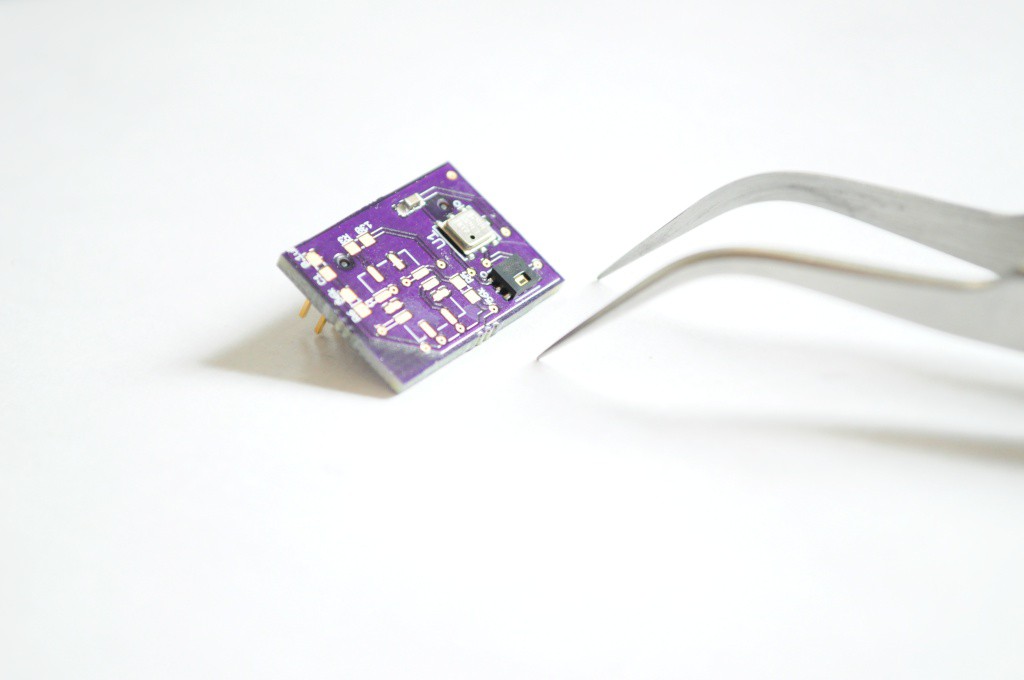
This is the first revision of the Atmospheric board -- you'll want to put together the second revision, with the mosfets for the gas sensor.
Lightning / UV board
![]()
You'll need to use hot-air reflow or reflow the board twice to properly reflow the tiny microphone on the back.
Capacitive Touch Sensor board
The latest revision of this board moves all the components except for two pushbuttons to the bottom side of this board. The whole thing can be easily reflowed without issue. The two LEDs/resistors beside the button are "do not populate" -- they're included incase you want to have a fancy glowing OK button, but are untested.
-
3Step 3
http://www.tricorderproject.org/arducorder/chipkit-mplab-ide-0023-arducorder.ziphttp://www.tricorderproject.org/arducorder/chipkit-mplab-ide-0023-arducorder.zip
Step 3: Constructing the Case
![]()
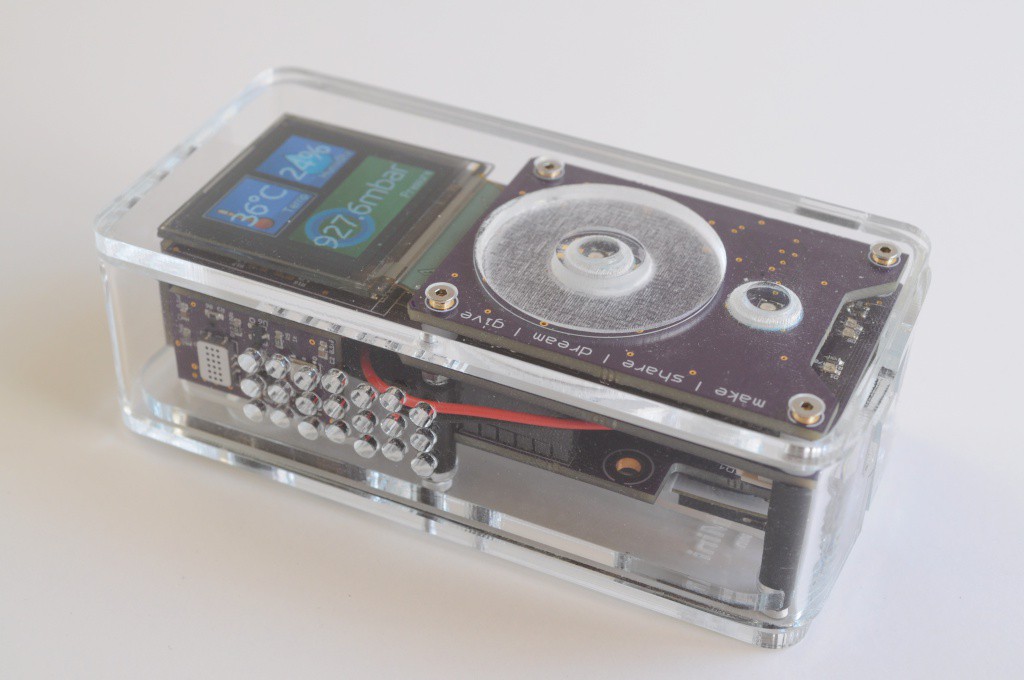
This beautiful case is constructed from laser cut acrylic -- part of which is engraved to make the touch wheel, and buttons. The side is easily manufactured by bending a long strip of acrylic with a normal hot air rework station.
Laser cut the acrylic
The enclosure is constructed from 1/8 inch (~2.9mm nominal) acrylic. The pattern files can be found on the Github repository under "mechanical".
While the back pieces are standard cutting and engraving, the side requires bending, and the top requires essentially using the laser cutter as a mill. The top process is as follows:
- Cut the top plate outline and M2 holes
- Cut an outline around the touch wheel
- Manually remove the plastic shroud on the acrylic, so the next engraving step won't leave any of the protective cover in the touch wheel engraving area
- Engrave the touch wheel (on the top of the acrylic) to ~2mm depth
- Carefully flip the top plate in place, using the acrylic sheet that it was cut from as a placement jig
- Engrave the bottom of the acrylic for the two button lips, and the buttons themselves -- these should also be engraved to ~2mm depth
- Cut the buttons
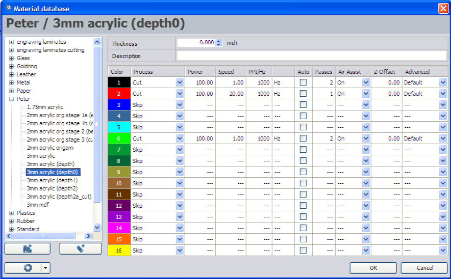
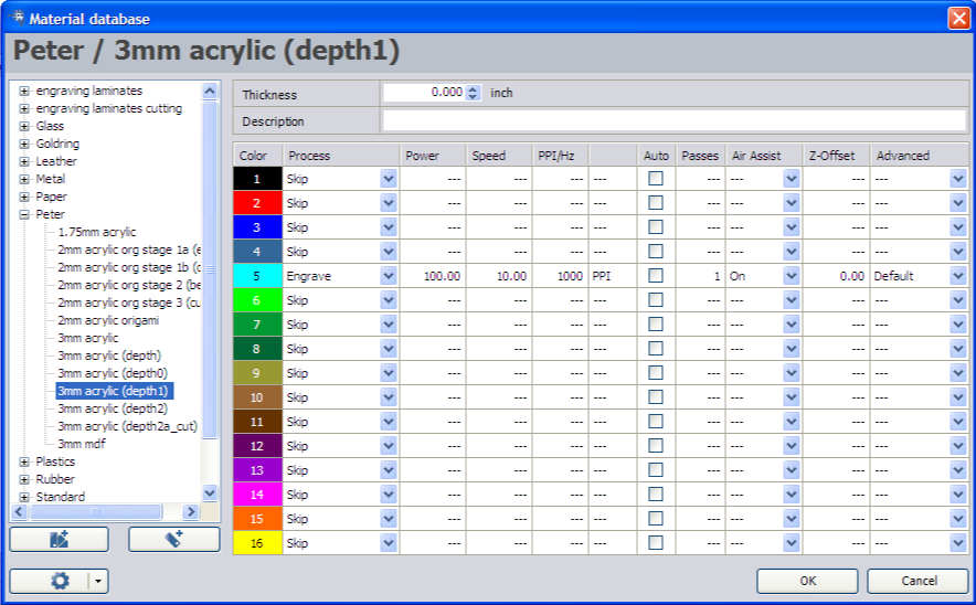
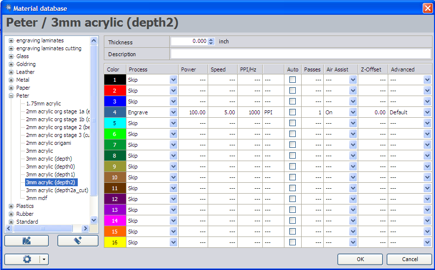
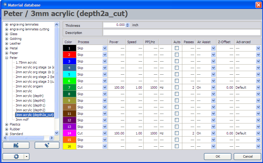
You will need to experiment to find settings on your laser cutter that engrave to the required depth -- this will take a few minutes of experimenting. The settings that I use for our Trotec 60W cutter at Xerocraft are:
Initial Cutting Step
![]()
Touch Wheel Engraving
![]()
Flip piece -- engrave buttons and button holes
![]()
Final step -- cut buttons out
![]()
Side Piece
![]()
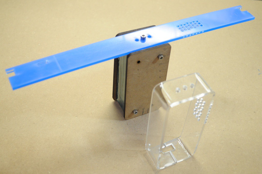
Cut out the bending jig out of 3mm MDF. There will be one extra middle piece that isn't required. The holes should snugly fit some number 6 screws, and hold the jig together. Don't forget to include a nut in the captive slot, so that you can securely hold the large side piece in place while you bend it.
This step takes a bit of practice, so I recommend cutting out a view side pieces to practice on. Using your hot air rework station set to around 250C, heat the bends one at a time until they very slowly bend into beautiful curves. For the two long pieces, I attached a counter weight on either end for leverage (Just taping a small screwdriver to the ends). This helps gravity along a bit. Try not to force the pieces -- let gravity do the work, and it'll look better.
It takes about 5 minutes per bend, or about 20 minutes total. If you have an actual acrylic oven meant for this, then you're job is a little easier -- although be careful not to bend the straight pieces, or it may end up looking more like a Picasso.
Assemble
![]()
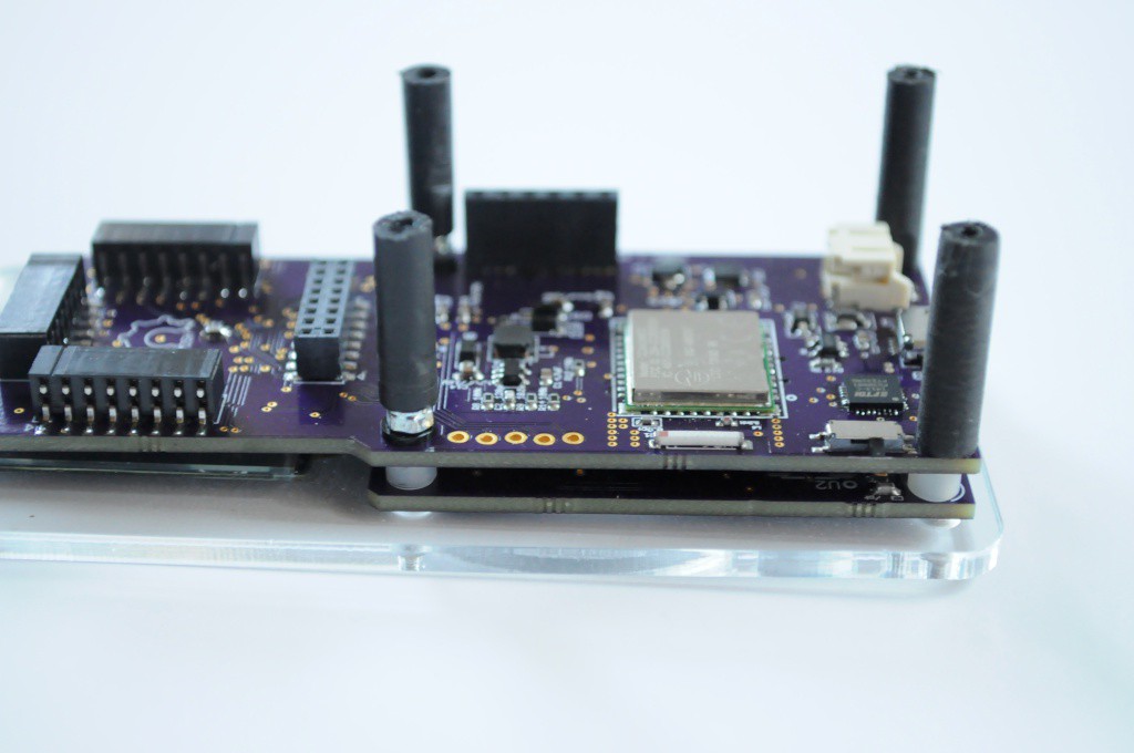
Countersink the four holes on the top plate. Using four M2x16mm countersunk machine screws, bolt the capacitive touch wheel board to the motherboard. Place four 3mm high M2 spacers between the boards. The two middle bolts should have M2 nylon washers, and M2 locknuts.
Attach four M2-tapped 5mm diameter delrin standoffs. You'll likely need to quickly machine these yourself, or purchase some nylon standoffs and tap them yourself. These act as the main fastener for the bottom two holes.
![]()
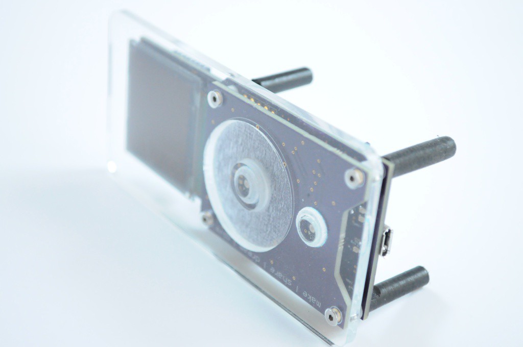
Ensure these are snug, but not too snug. It's critical that the acrylic faceplace makes very good contact with the capacitive touch wheel for normal operation.
![]()
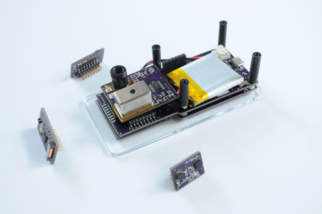
Attach the battery, with the cable snaked over the top of the spectrometer board connector to take care of any slack. Attach the spectrometer board next, then the three side-mounted sensor boards.
![]()
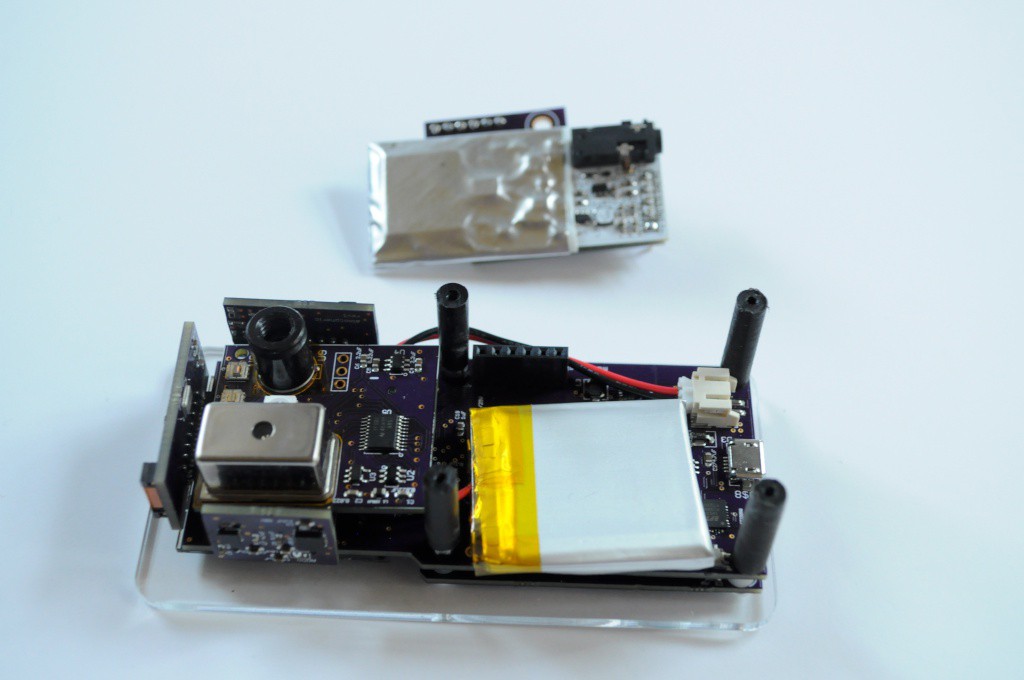
Next up, attach the radiation sensor board. This should snugly fit between the standoffs, keeping everything in place.
![]()
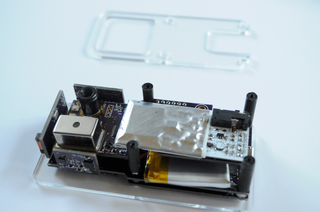
Next we'll attach the first bottom plate -- this one snugly fits onto the four 5mm standoffs, and provides a lip for the side piece to rest on.
![]()
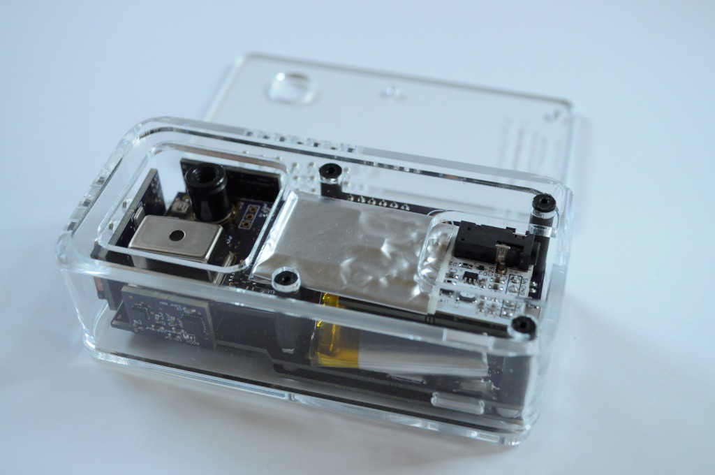
Next we'll place the side piece on -- this should snugly fit around the top bottom plate
![]()
Last, we'll install the bottom plate with the engraving. The four M2 holes here should also be countersunk. This acts as a retainer plate, very snugly keeping the sides together without any adhesive, so that you can take it apart to tinker without issue.
![]()
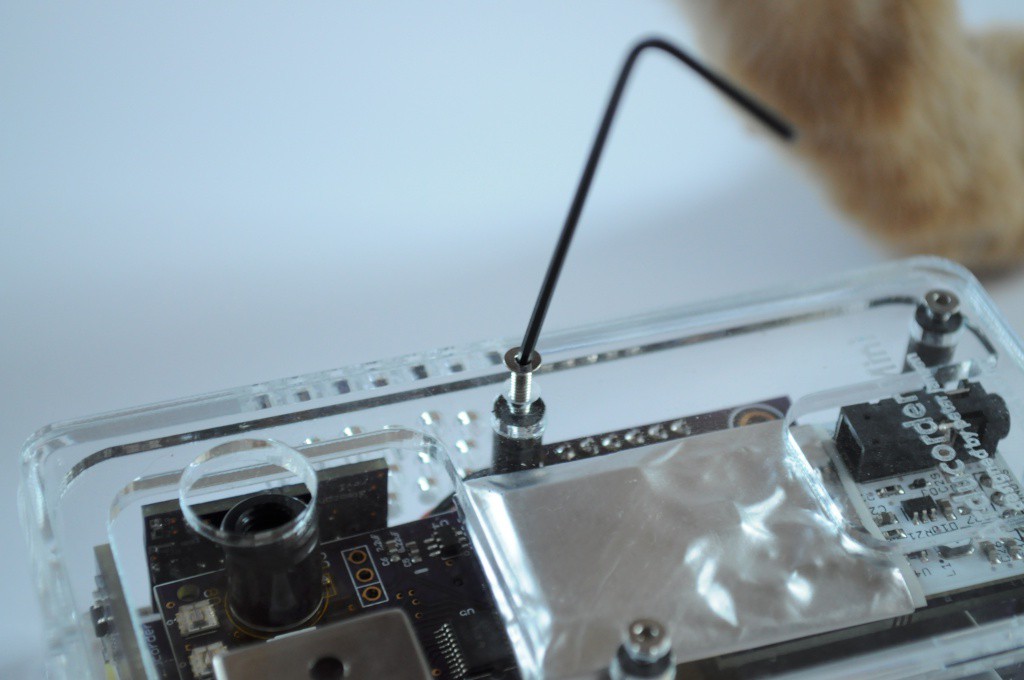
Fasten with four M2x12mm countersunk machine screws.
![]()
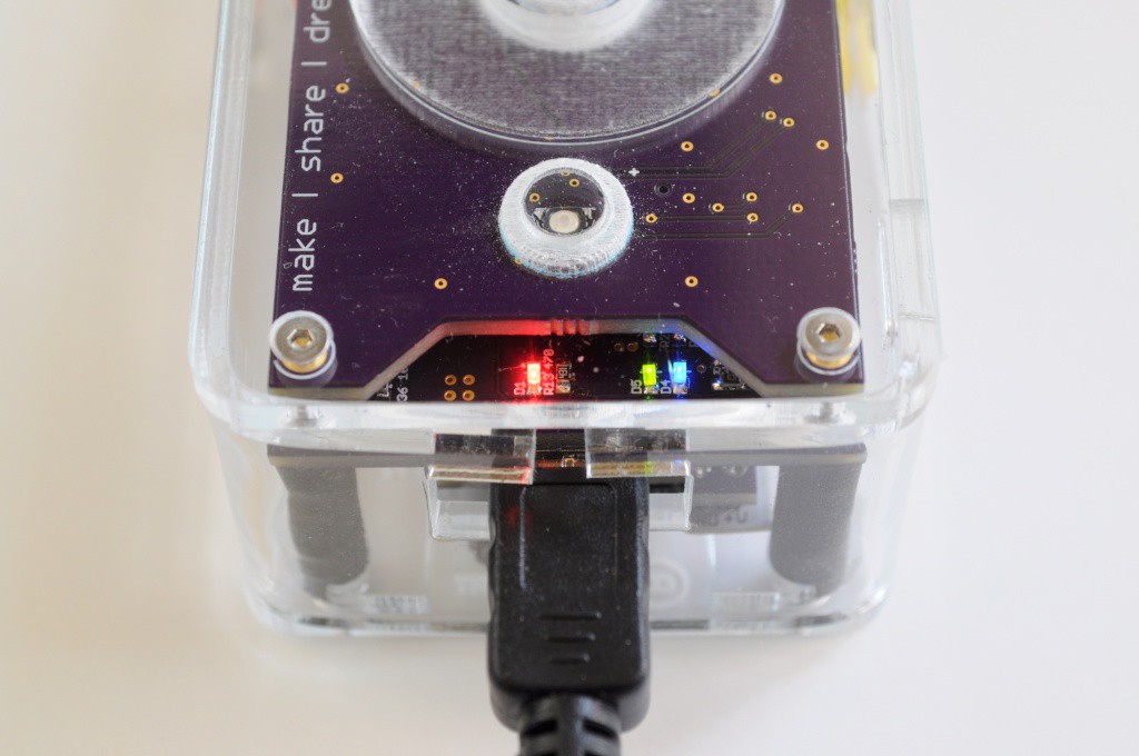
Plug in the USB cable, and view the beautiful LEDs telling you how great a job you did. Red means the battery is charging, green and blue mean serial communication over USB for firmware programming. If you haven't already, download the Arducorder-modified ChipKit IDE, which updates some of the Arduino libraries towards 1.X compatibility. Grab the latest firmware from the Github Repository (currently test2k) and program the device. The firmware is very large, and will take a few minutes to upload and verify.
![]()
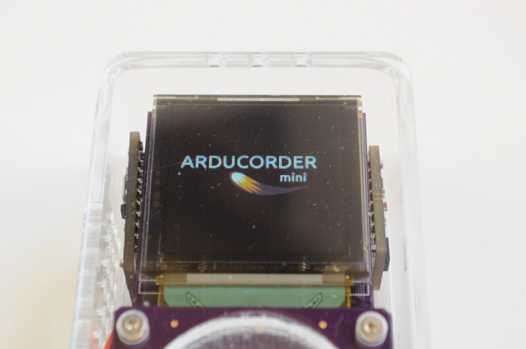
The firmware will display this splash screen during boot up. It should be on the screen for a few seconds while all the sensors are initialized.
![]()
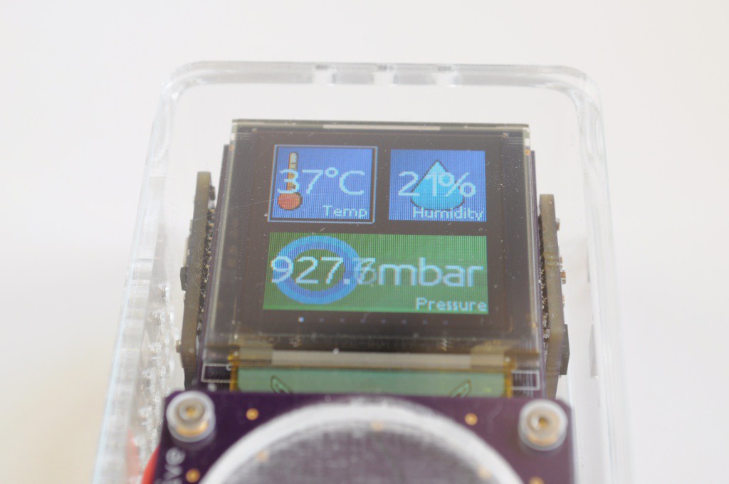
After booting, your Arducorder Mini should begin to display the tile interface. Go explore the world, and share your discoveries with your friends!
Open Source Science Tricorder
Science in your hand. A pocket-sized instrument capable of visualizing and exploring the world around you.
 peter jansen



Discussions
Become a Hackaday.io Member
Create an account to leave a comment. Already have an account? Log In.