 peter jansen
Finals Video
Semifinals Prototype Video
Concept Video
Hardware and System Design
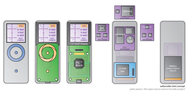
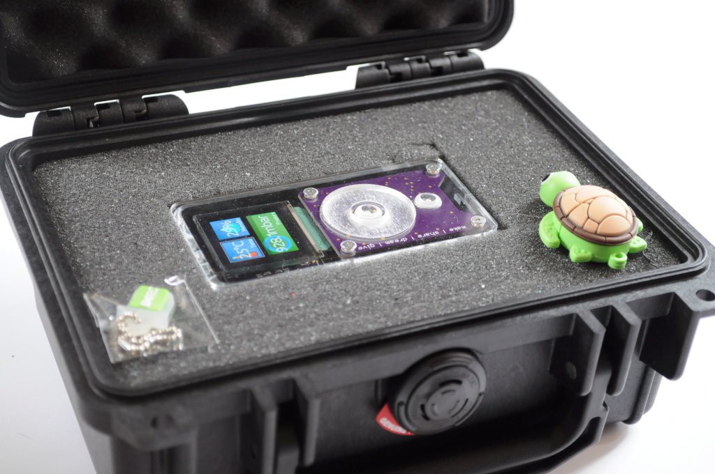
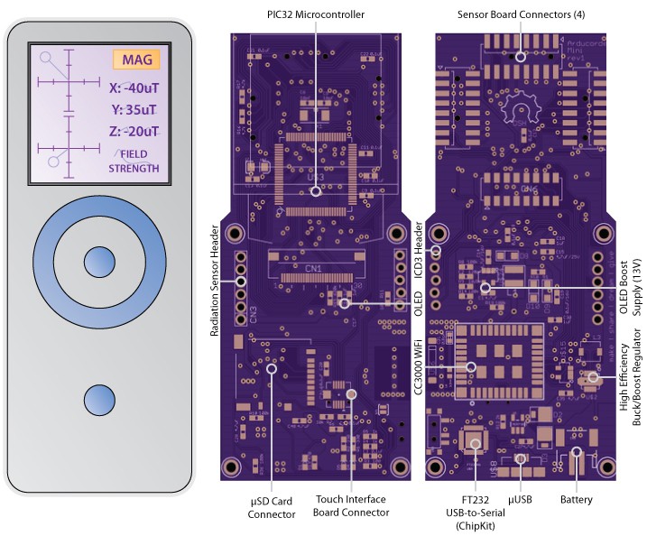
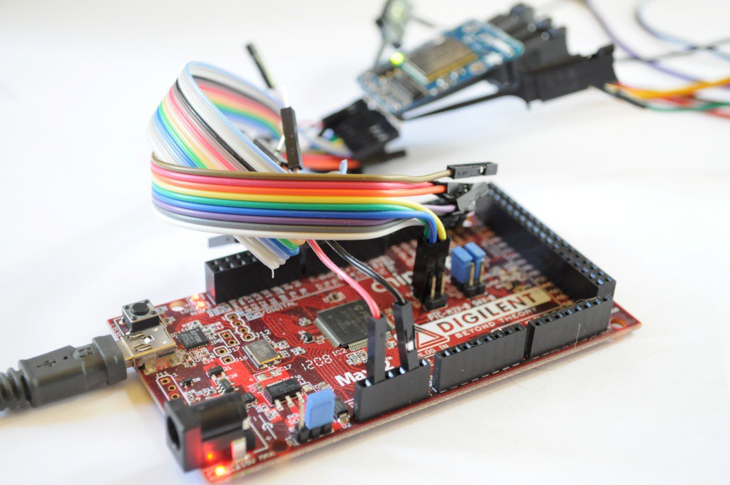
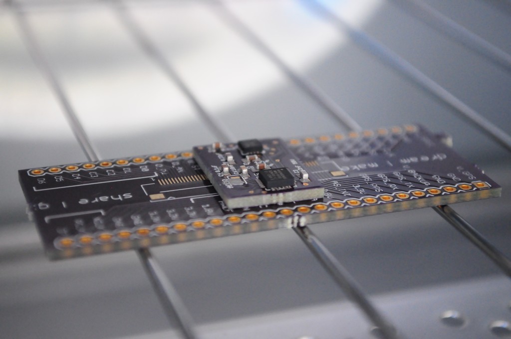
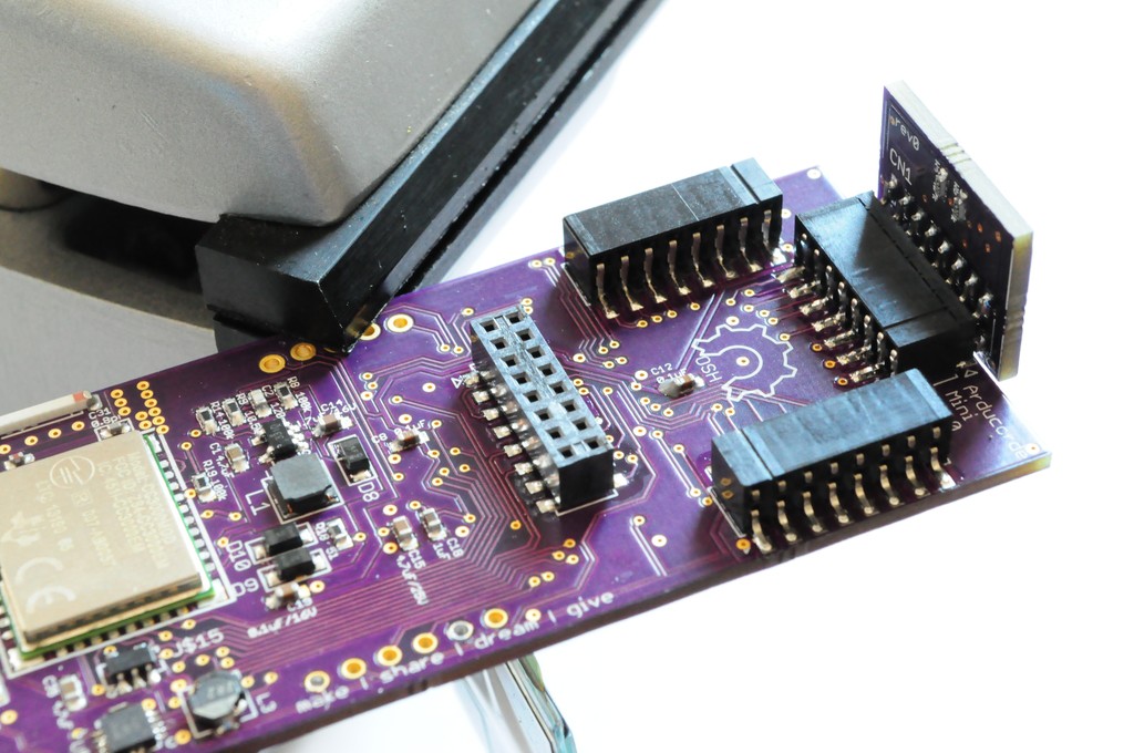
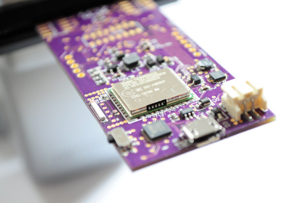
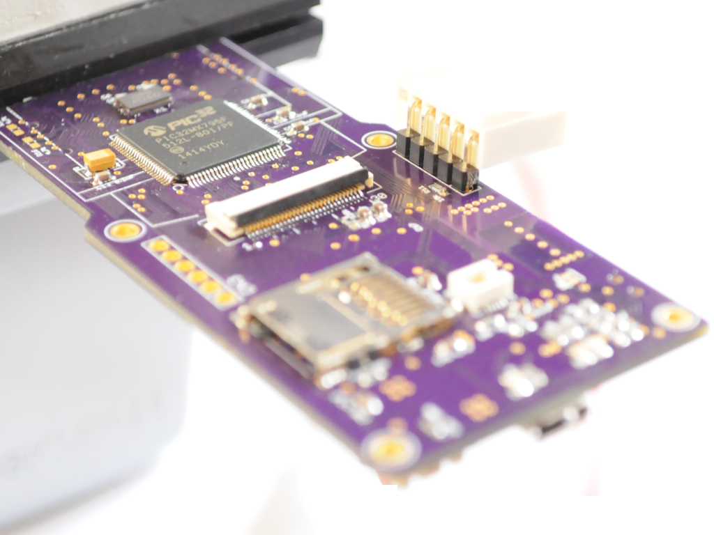
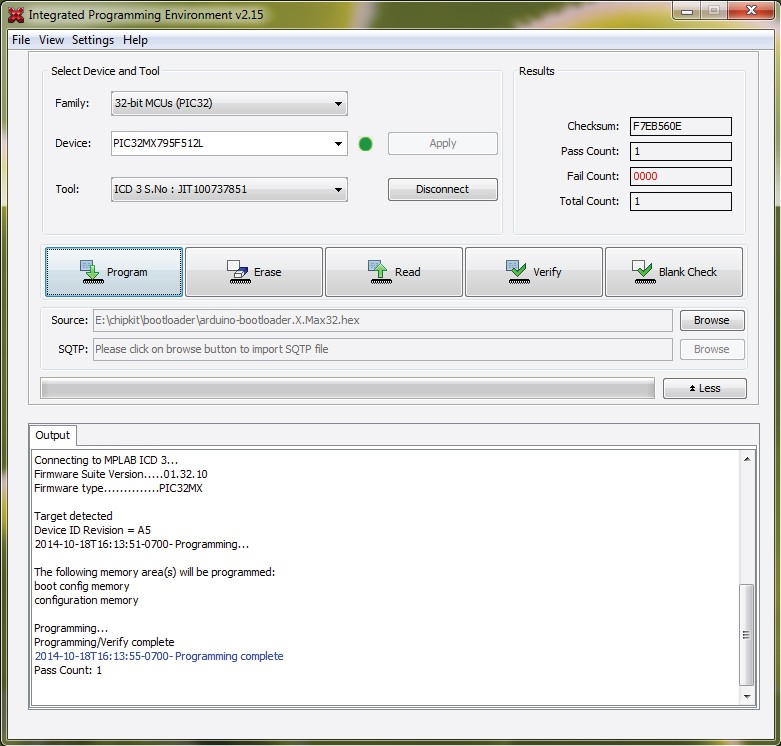
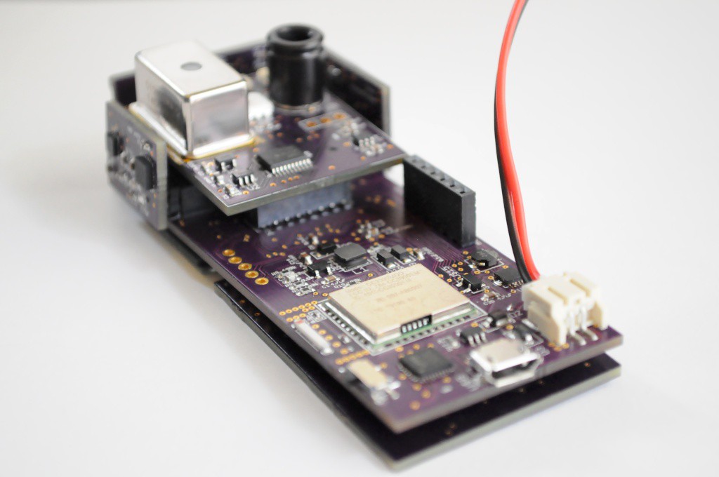
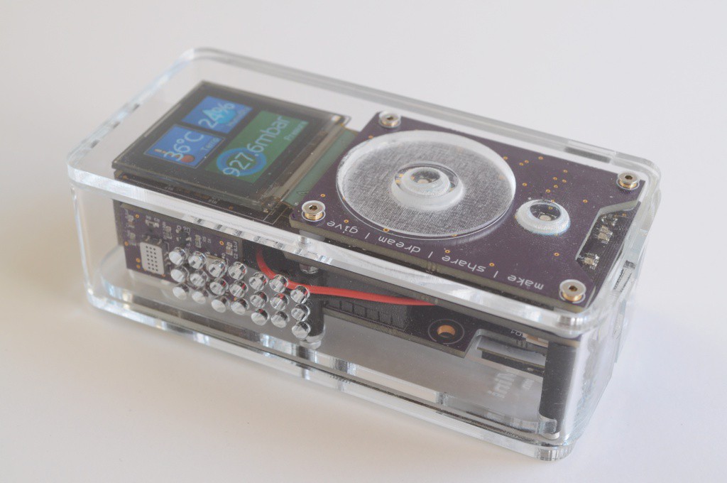
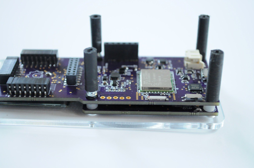
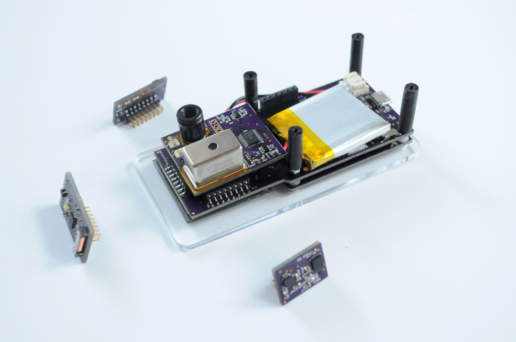
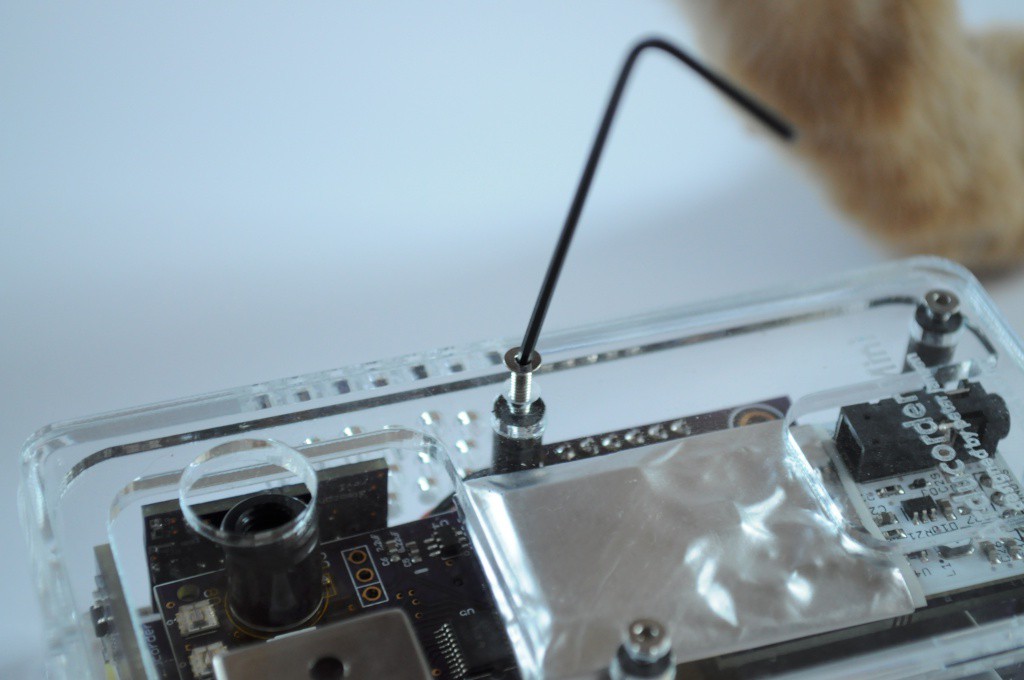
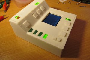
The Arducorder Mini is an Arduino-compatible handheld sensing device, and the next iteration of my open source science tricorder-like device project that's designed to be easy to use, have a large array of sensors, and easy to share sensing discoveries. The Arducorder Mini is designed to foster a community of open source users and development, and is ChipKit MAX32 compatible, which is a port of the Arduino platform to the much more powerful PIC32 family, and makes use of a PIC32MX795F512L with 128k of RAM, 512k of flash, a zippy 80Mhz processing speed, and a fantastic set of peripherals for interfacing to sensors.
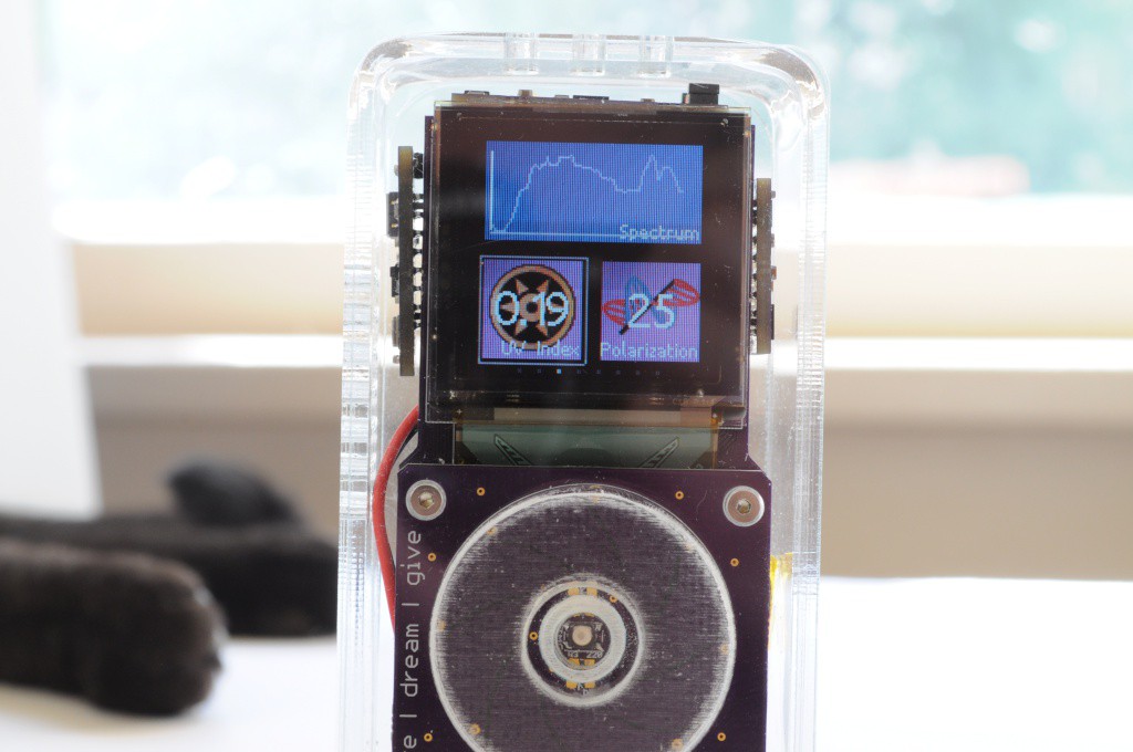
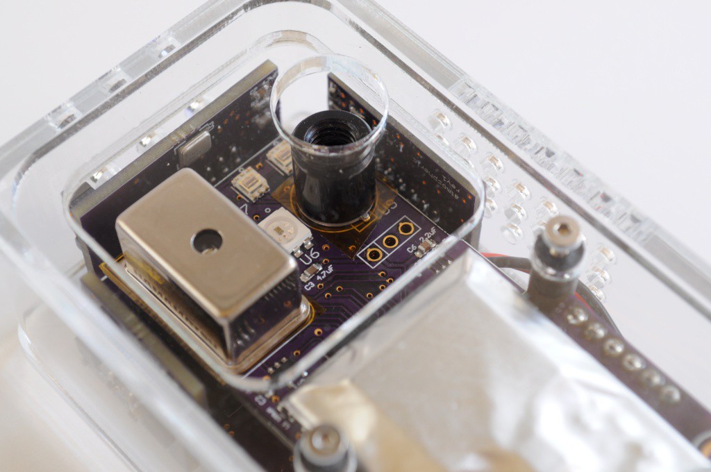
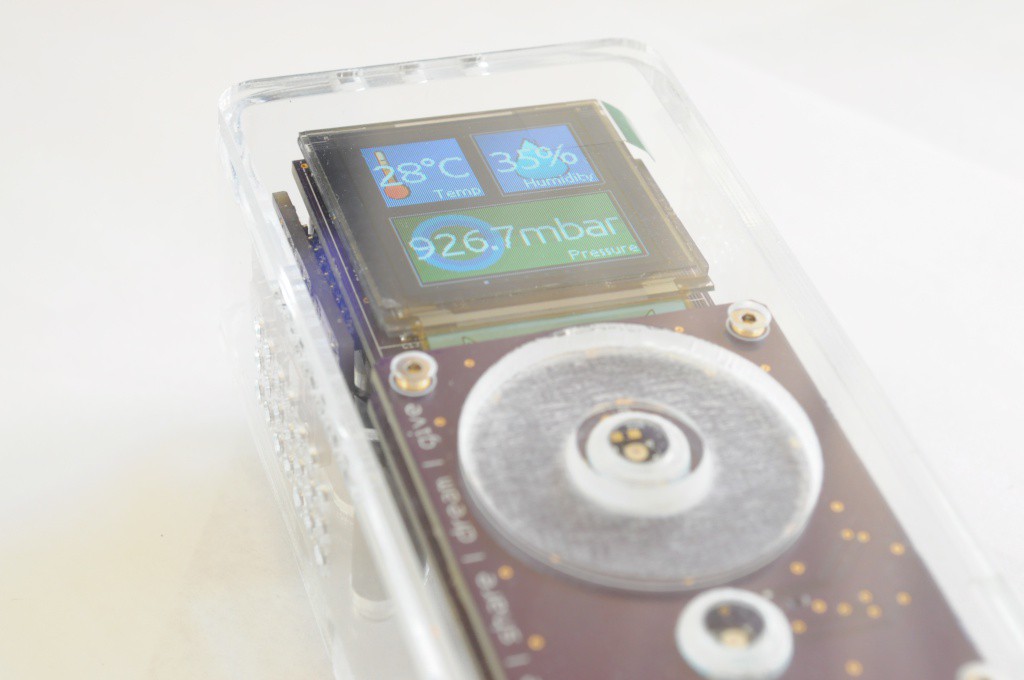
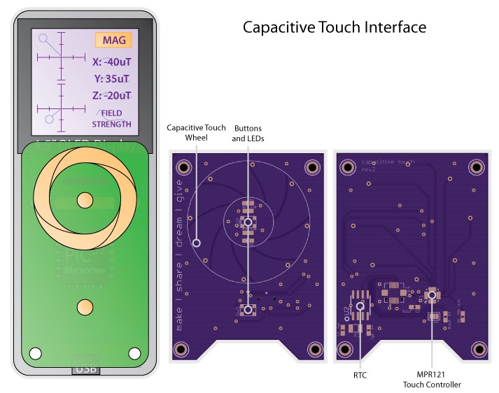
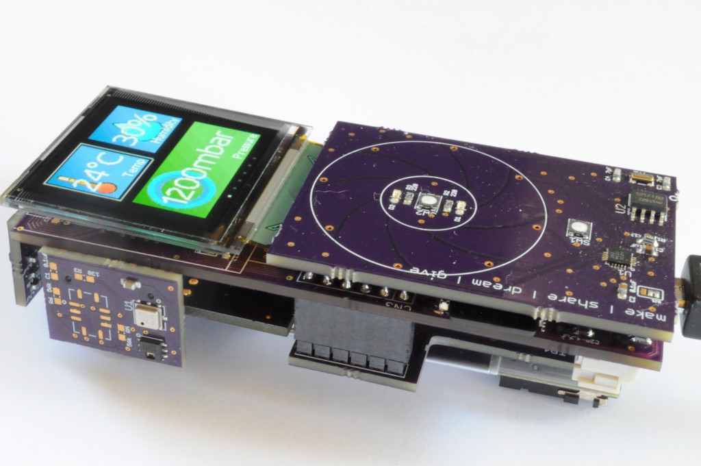
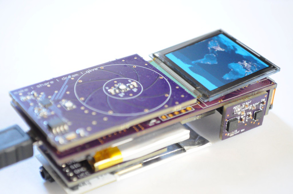
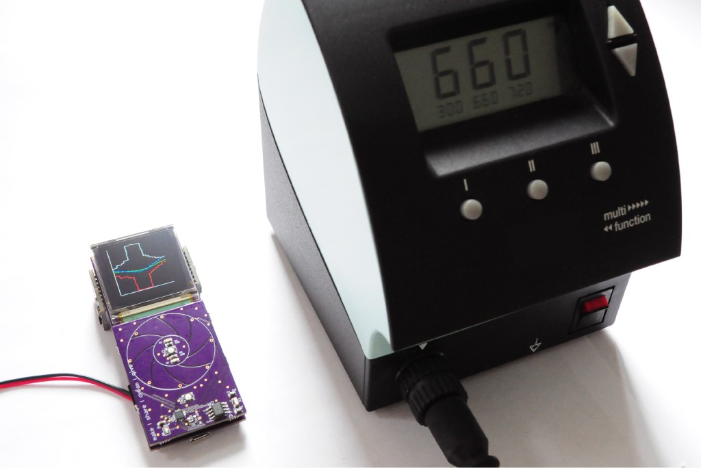
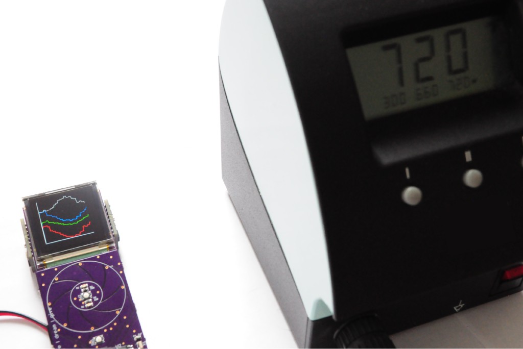
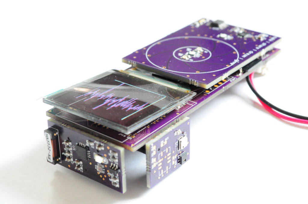
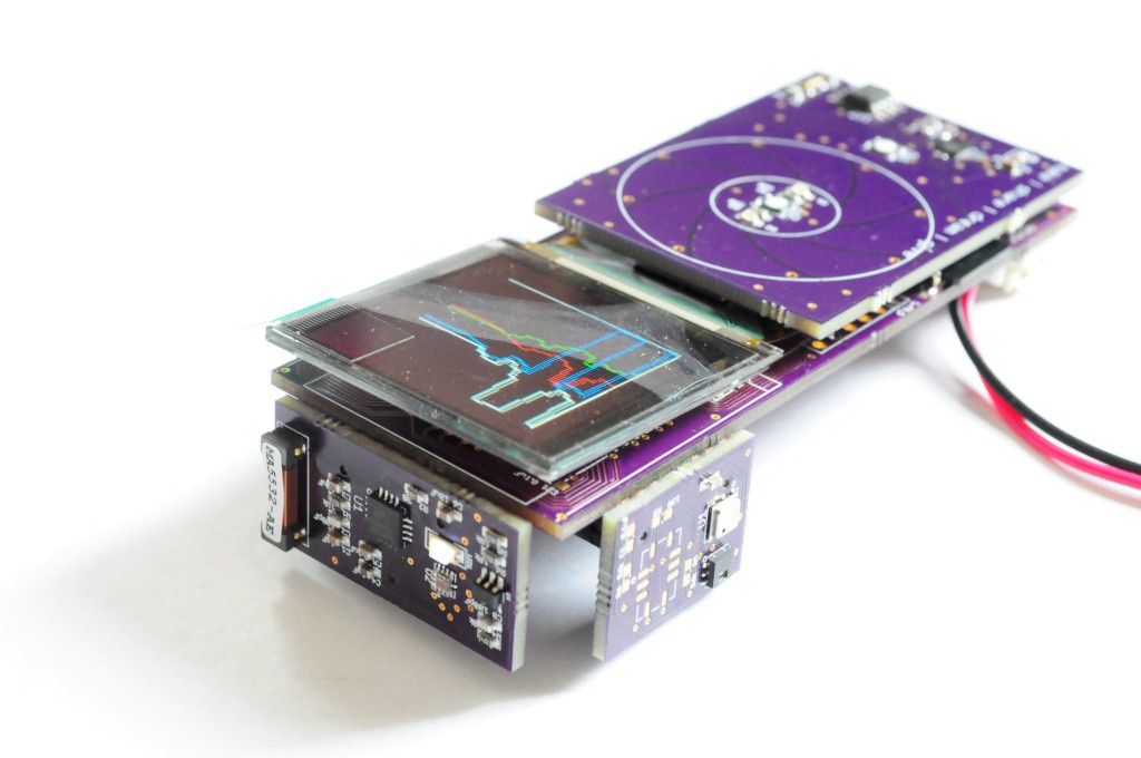
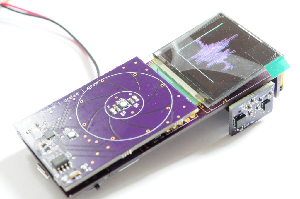
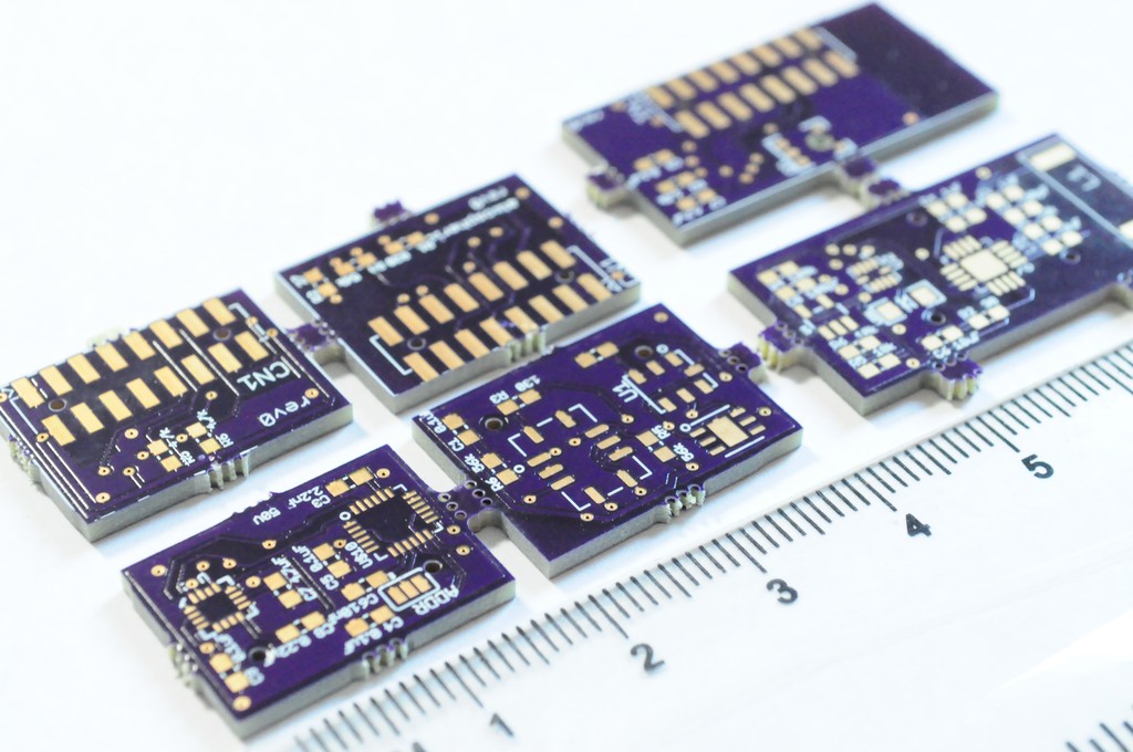
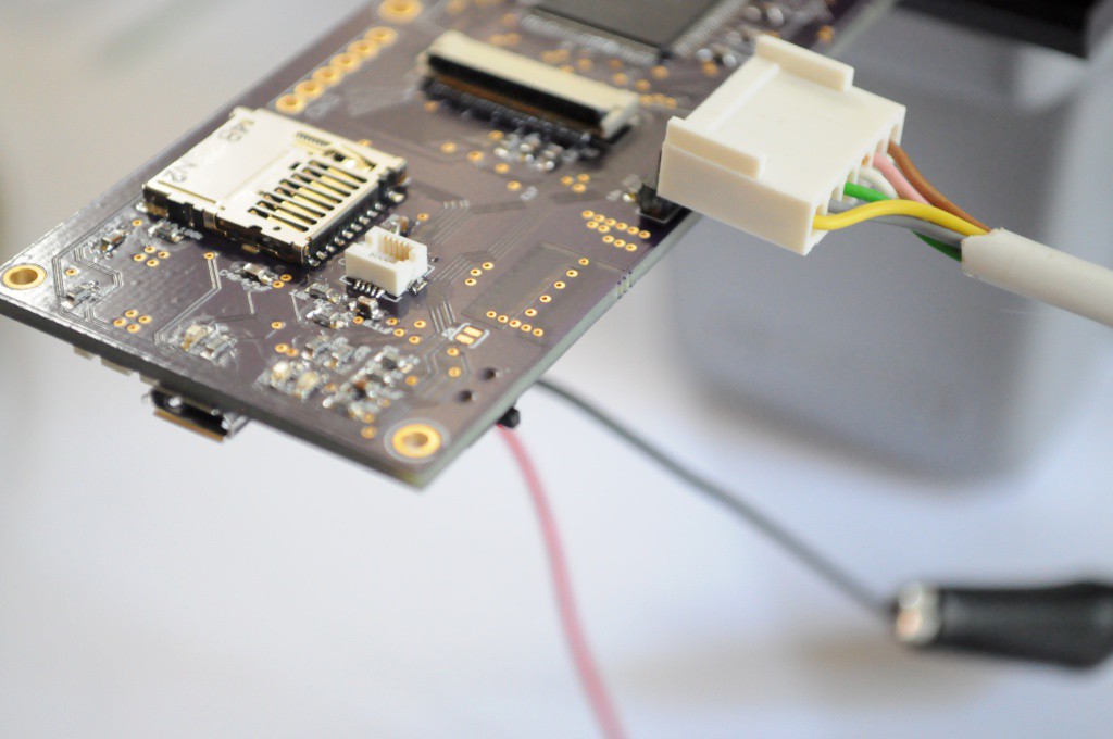
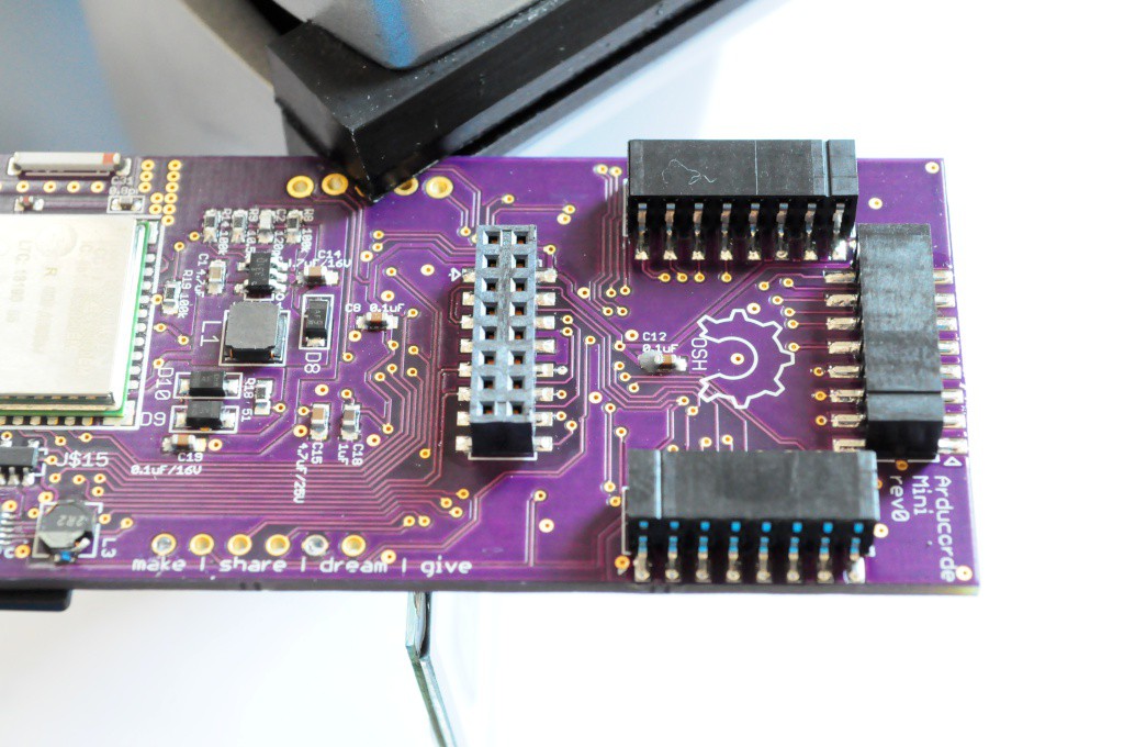
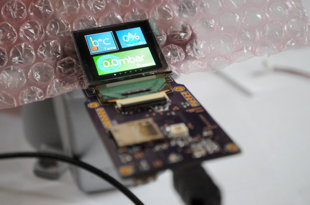
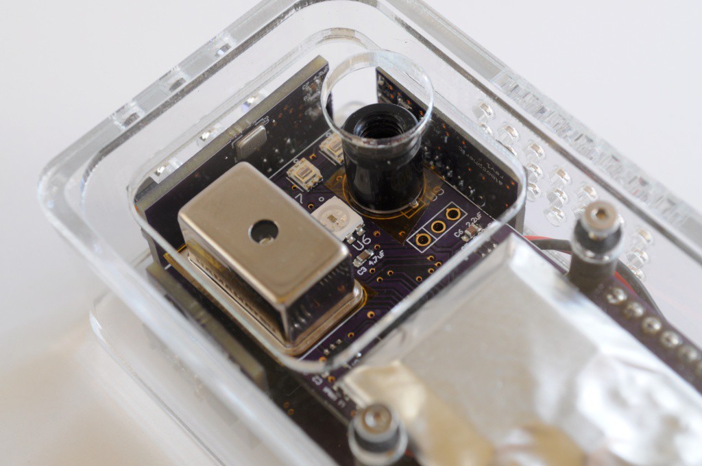
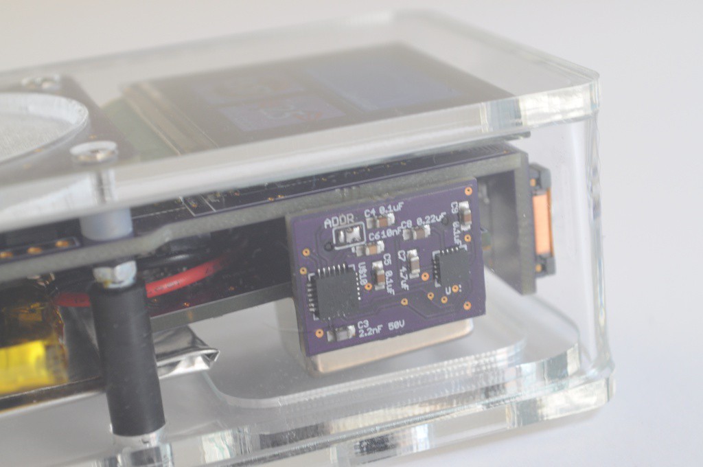
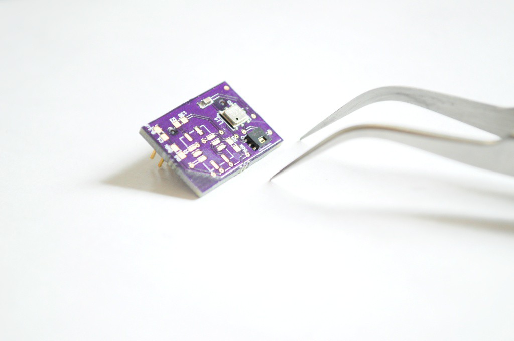
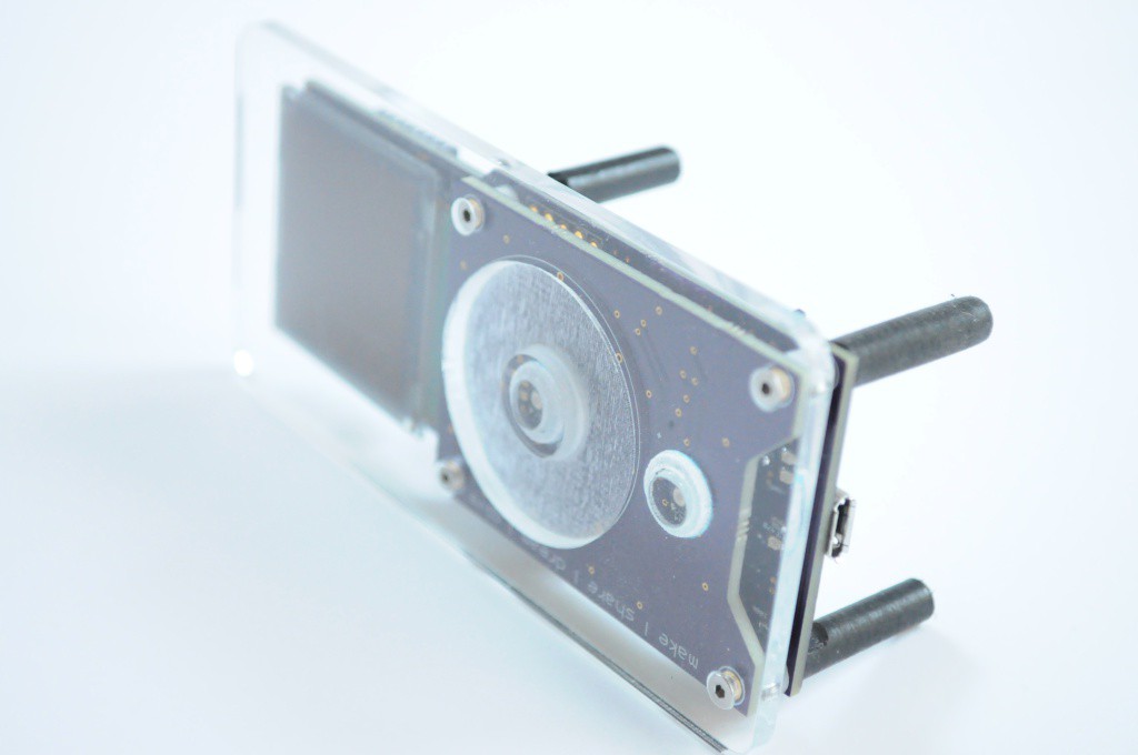
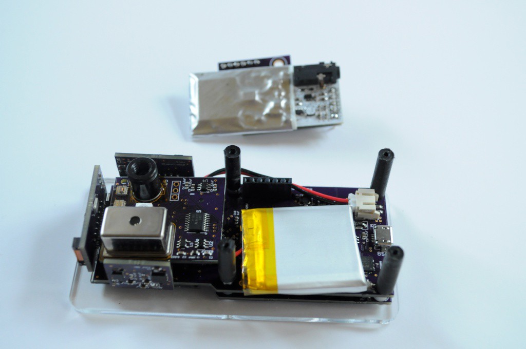
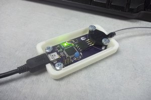
The current prototype is designed to use a 1.5" OLED with 128x128 pixels and 16-bit colour, a touch interface, and connectors for 5 modular sensor boards that each contain several sensors. The sensor boards are designed to be interchangeable and upgradable, so that a large number of configurations are possible with different sensing capabilities and price points.
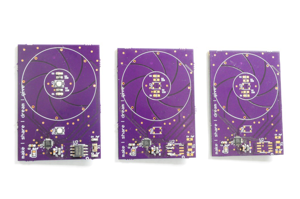
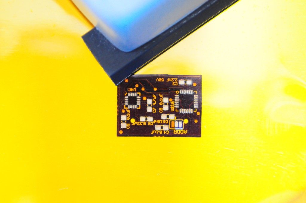
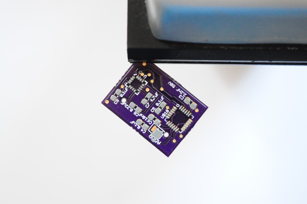
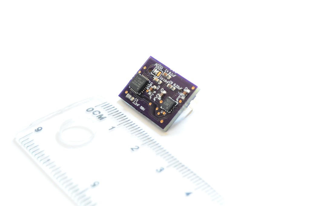
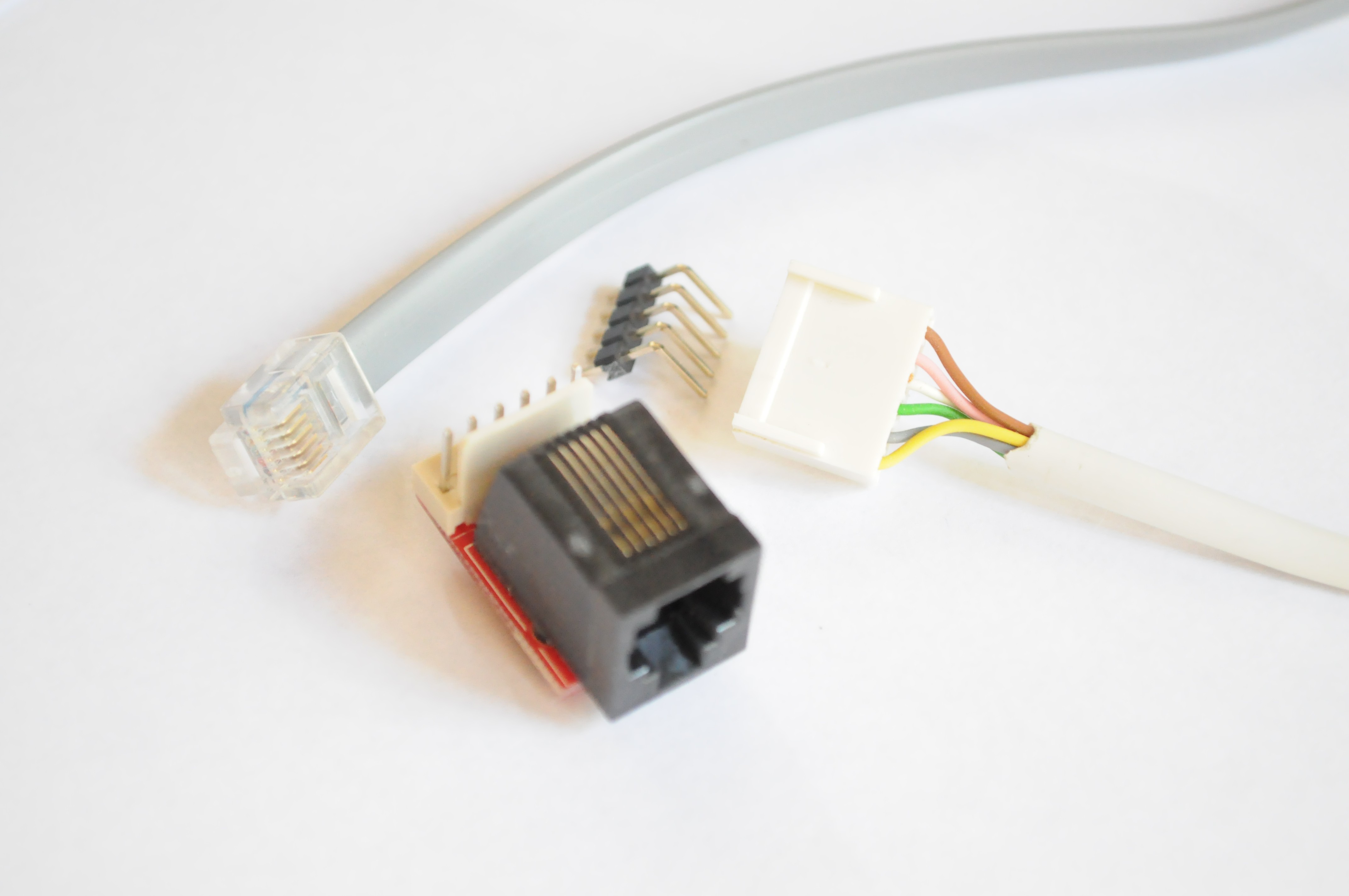
While the Arducorder Mini is being designed with a wide array of sensing capabilities off-the-shelf, it's also designed to be easy for folks to tinker with and upgrade. Accessibility is a central goal of the project -- If you're familiar with Eagle CAD and have ever made an Arduino shield, it should be easy to design your own sensor board. Using OSHPark and Digikey, the parts cost for a new sensor board (PCB and header, not including sensors) is about $5, which is even less than most protoboards!

Sensing Capabilities
The current prototype has been designed to include the following sensing capabilities:
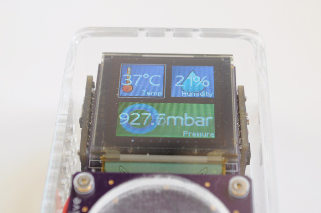
Atmospheric Sensors
- Ambient Temperature and Humidity: Measurement Specialties HTU21D
- Ambient Pressure: Bosch Sensortec BMP180
- Multi-gas sensor: SGX-Sensortech MICS-6814
Electromagnetic Sensors
- 3-Axis Magnetometer: Honeywell HMC5883L
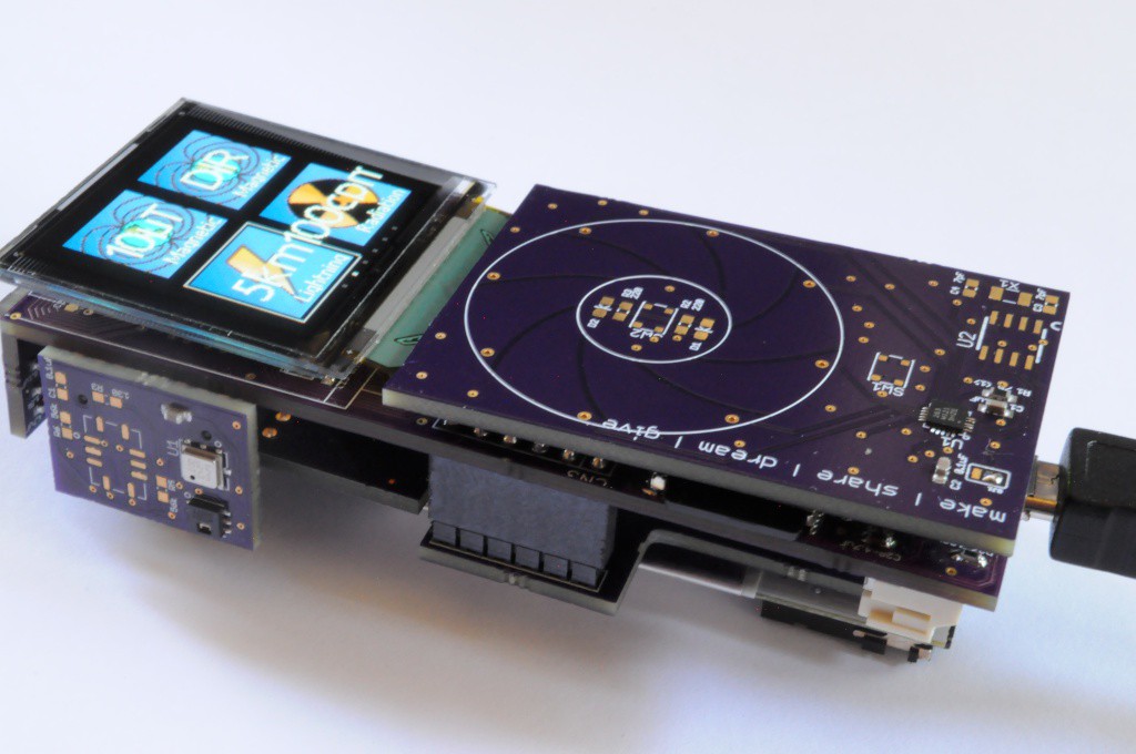
- Lightning sensor: AMS AS3935
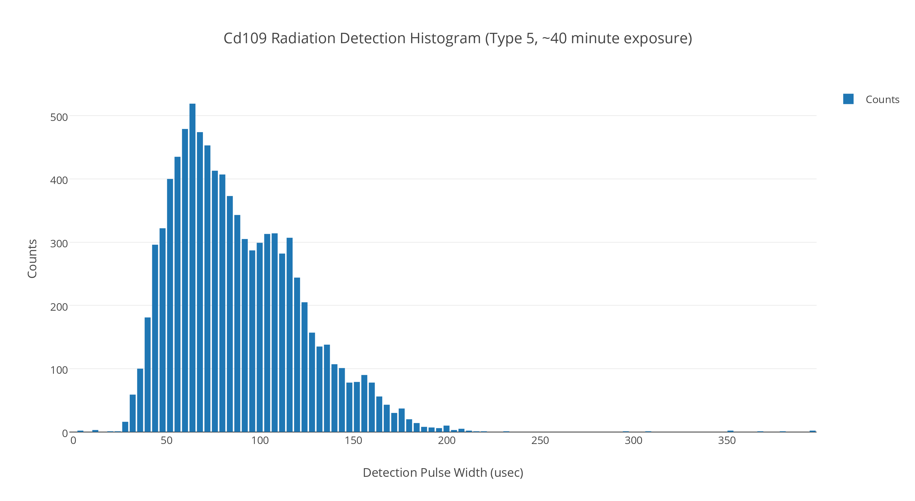
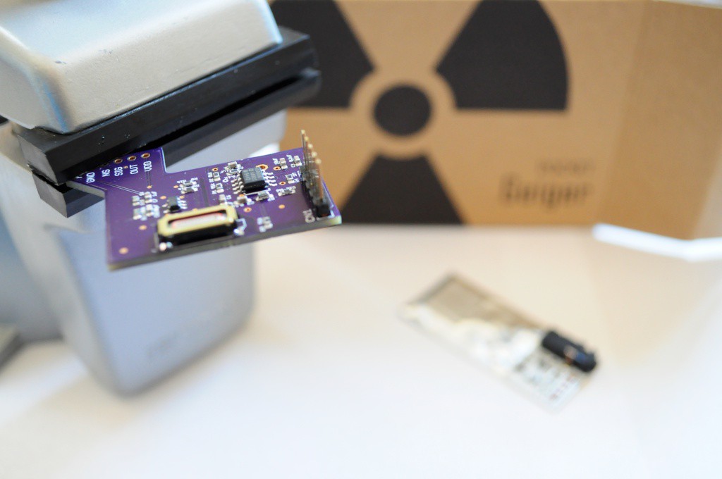
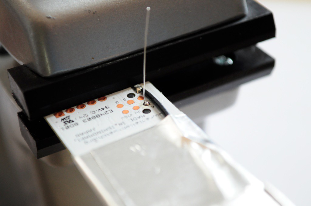
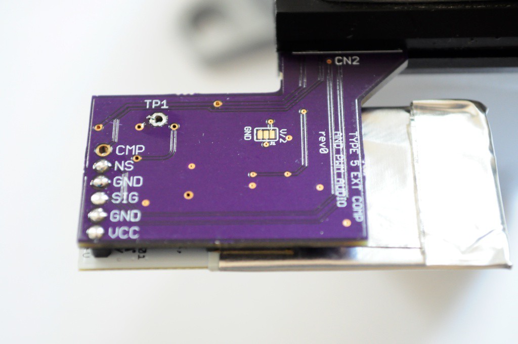
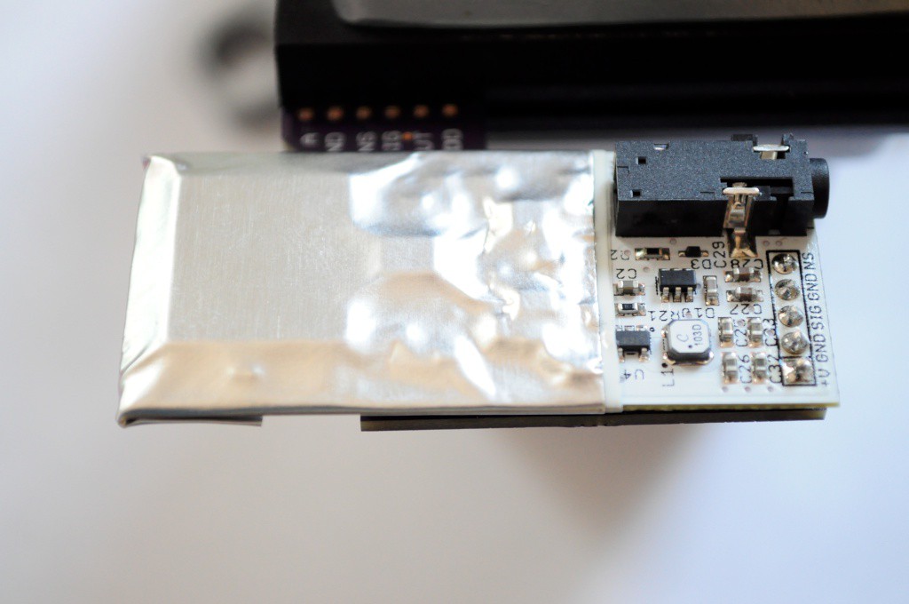
- X-ray and Gamma Ray Detector: Radiation Watch Type 5
- Low-resolution thermal camera: Melexis MLX90620 16×4
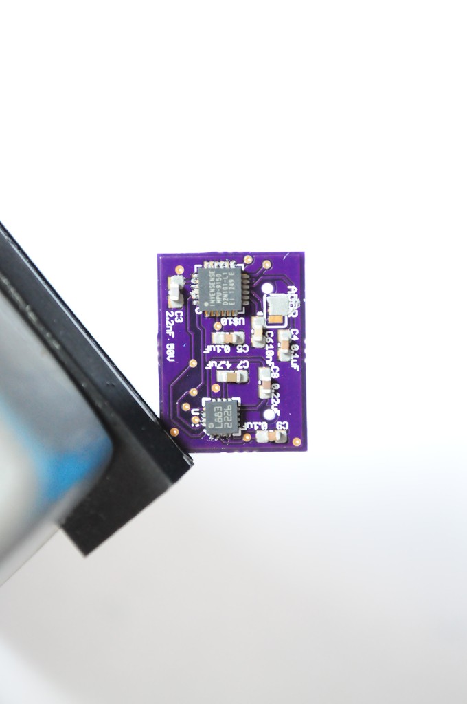
- Home-built linear polarimeter: 2x TAOS TSL2561
- UV: Silicon Labs Si1145
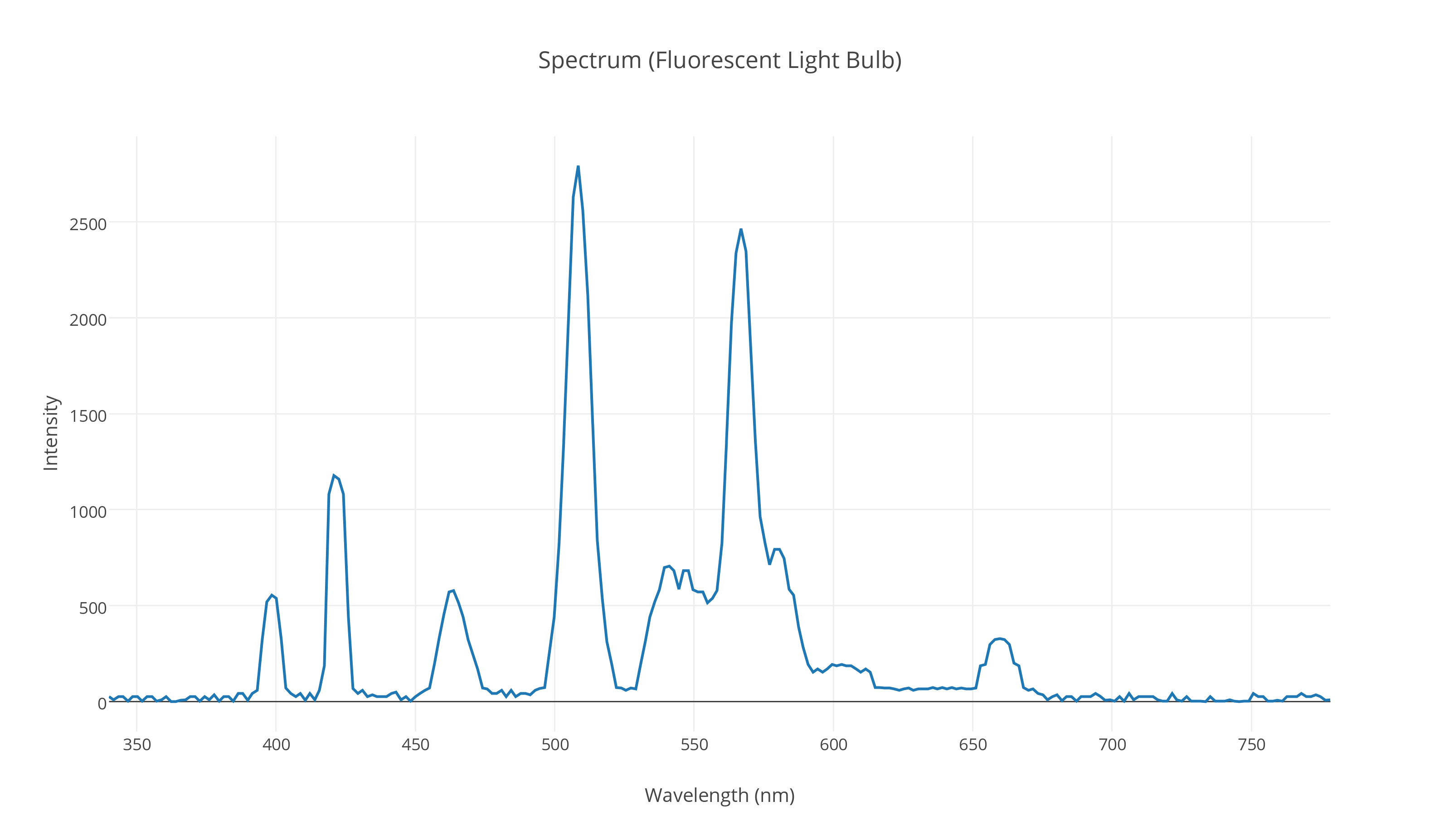
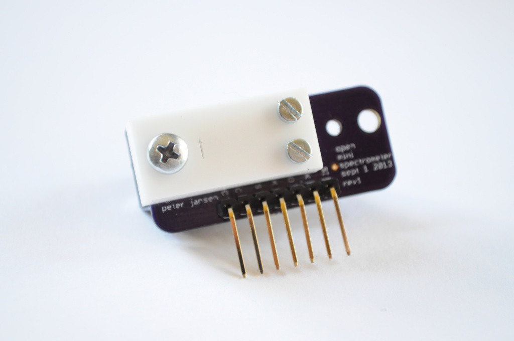
- Spectrometer: Hamamatsu C12666MA micro-spectrometer, with NeoPixel light source
Spatial Sensors
- Inertial Measurement Unit: Invensense MPU-9150 9-axis (3-axis accelerometer, gyro, and magnetometer)
Other Sensors
- Microphone: Analog Devices ADMP401
Check out the project logs for the current build progress, and stay tuned!
GitHub Repository and Source Files
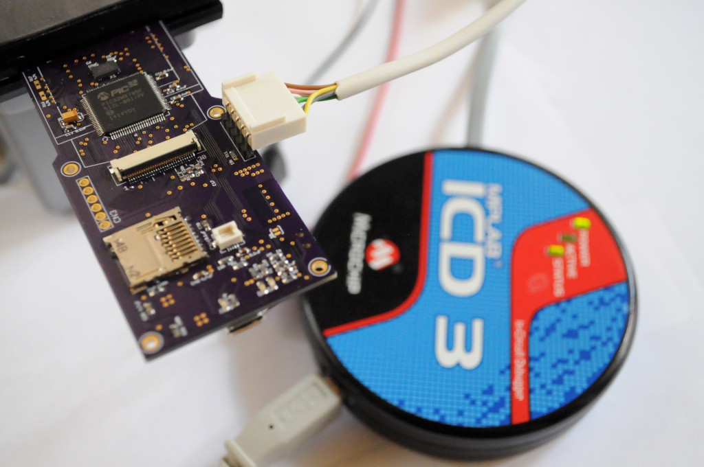
The source files are available on the Arducorder Mini GitHub Repository as the development progresses. The hardware is licensed under Creative Commons By-Attribution Share-Alike 4.0 International, and the firmware and libraries are available under various open licenses. Please see the licenses file included with the source for more information.
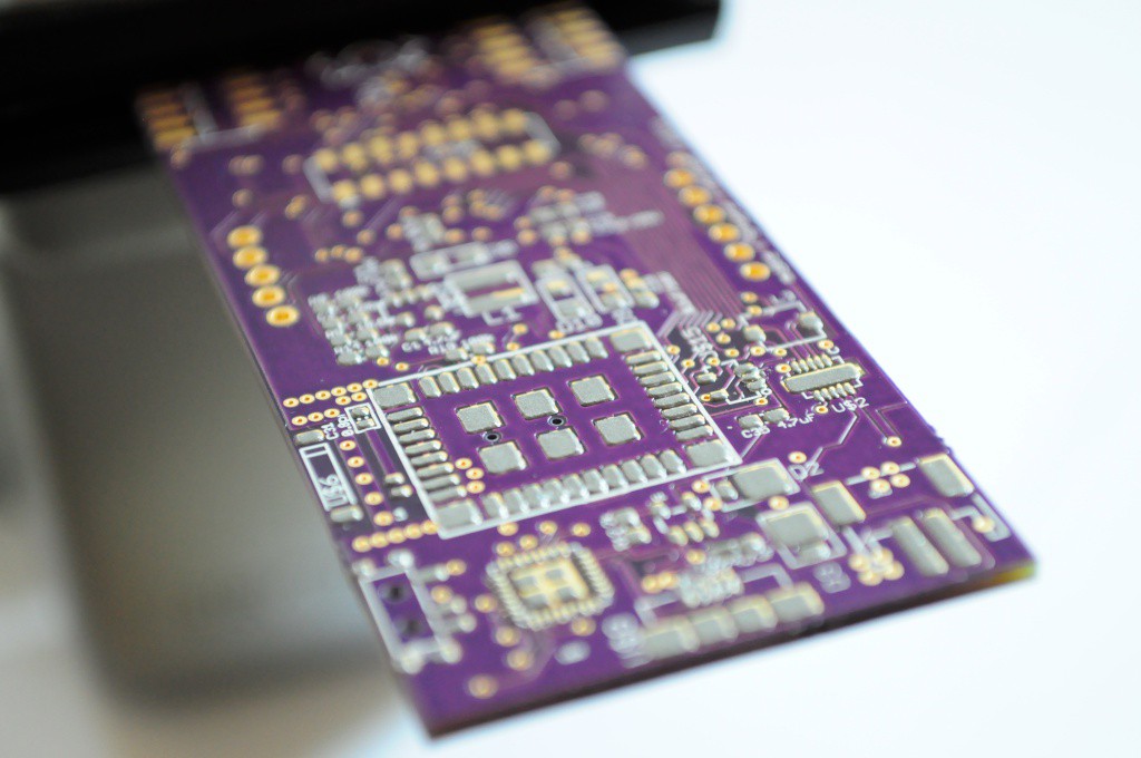
Gerbers and Parts List
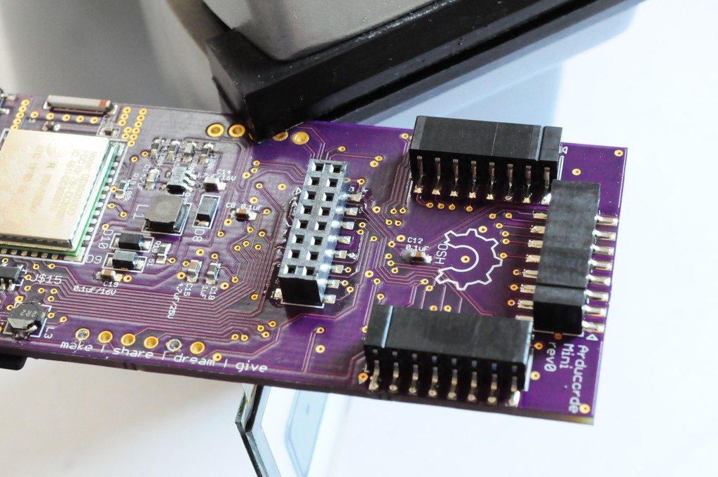
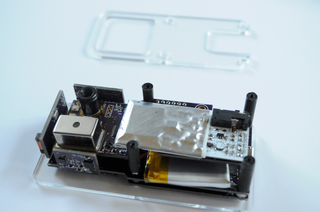
While the major parts are listed below, the Arducorder is a modular ecosystem of seven boards -- including the motherboard, capacitive touch interface board, and five modular sensor boards. The hardware folder of the Github repository contains the latest Eagle source files, and gerber files that can be uploaded directly to OshPark. While the Eagle files contain internal parts lists, this source directory will also maintain PDFs of schematics and separate parts listings.
Contributions
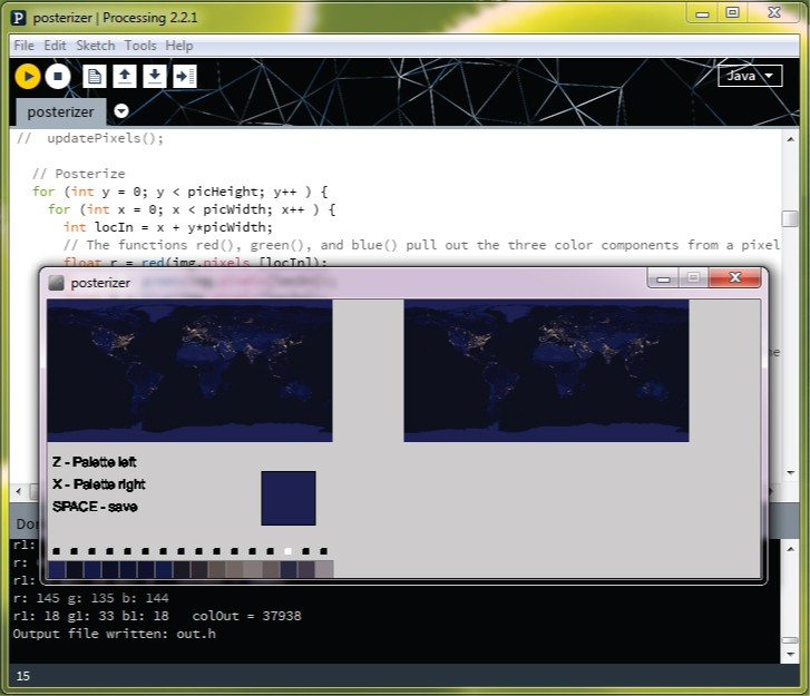
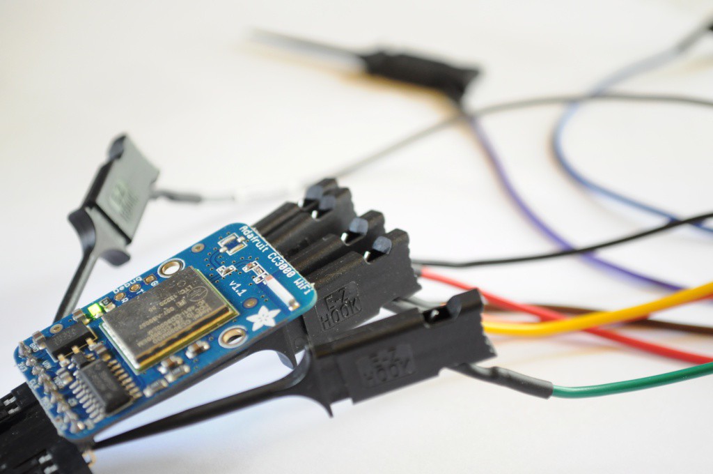
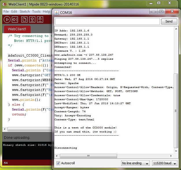
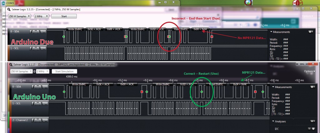
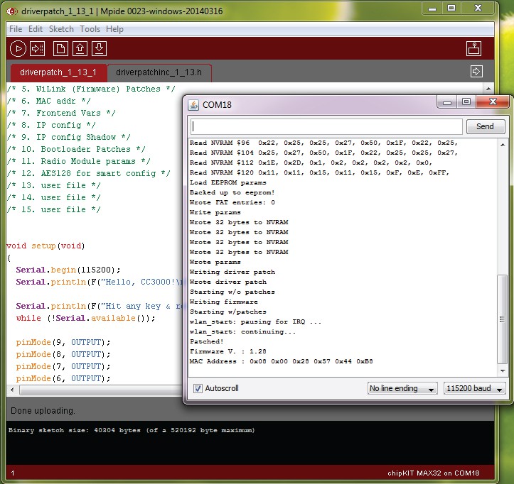
In addition to the device, this project has developed open source Arduino-compatible libraries for a light weight live tile based graphical user interface, supporting tools, open libraries for new sensors including the Radiation Watch Type 5 and Hamamatsu micro spectrometer, additions to the Adafruit MPR121 library to support capacitive touch wheels, and a port of the Adafruit CC3000 WiFi module to the Chipkit MAX32 platform. I have also greatly expanded the Plotly library for Arduino, which now supports multiple streams, much faster transfer speeds, and sending normal (non-streaming) plots. I have also partially updated the ChipKit IDE I2C and Client/Server libraries to partial...
Read more »


 jaromir.sukuba
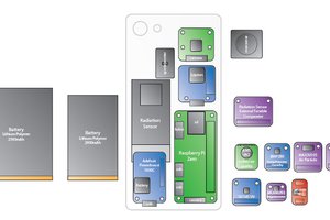
 Jason Webb
 Tom Meehan
This is really cool. If these were available premade, or mostly-made, I'd buy one. I have no idea what I'd do with it, but I'd still buy one.