 siliconlabs
Minecraft + Lego
Let’s take a closer look at the Lego kits. It’s all there, from the small hut that will let you survive your first night, to the zombies that want to eat you, and the creeper who wants to blow you up. And, of course, a Minecraft kit wouldn’t be complete without torches. When building the kit, I noticed that the torch was hollow, and that the base was roughly 3mm in size, perfect for a small LED. Using a breadboard, a resistor, a white LED and a little bit of putty, I noticed that the light could shine through, adding a warming glow to the kit. However, torches aren’t stable light sources, they tend to flicker, so it was time to investigate.
To simulate a flickering candle, you normally need two red LEDs and a yellow or orange LED. Three LEDs don’t fit, and besides, the transparent bricks on the top already change the color, so I had to do with a single white LED. PWM came to mind. By modifying the frequency, I could get the LED to change brightness, and by repeating that often enough, it could look as if it flickered. The problem is, the BGM111 doesn’t have PWM output. It does, however, have an easily accessible I2C port, so I went looking for PWM expansion cards.
Adafruit to the rescue
The Adafruit 16-channel 12-bit PWM board (https://www.adafruit.com/product/815) was a perfect fit for my needs. It is small, but feature packed. It can handle up to 16 LEDs using a single I2C address, and the address is easily changed. Also of interest is the build in 220-ohm resistor for each output. This makes LED driving trivial; just plug in the LED, and you’re good to go. Oh, and it’s made by Adafruit, so you know it’s well designed, and has excellent source code available.
I ordered one, and it arrived the next day. Solder time! The board has 16 3-pin outputs; V+, GND and PWM. It doesn’t get much easier than this. On the left and right of the board are the power and data connectors, designed so that they can be chained together. Adafruit says that you can chain 62 board together, for a total of 992 PWM outputs. Adafruit, if you are listening, I’m interested in giving this a shot!
Before putting that soldering iron away, don’t forget to change the board’s I2C address. The temperature sensor on the WSTK uses address 0x40, so change the Adafruit address to something else. For this one, I used 0x41, and maybe I’ll get my hands on a few more later on.
Blinky things!
It’s time to connect. The SDA/SCL and power pins are clearly marked on the Adafruit board, and if you turn the SiLabs board over, you can see the pinout for the expansion header. The green LED on the Adafruit should light up, telling you the power is OK. Now it’s time to work on the software.
I wanted to get things up and running as fast as possible, so I used BGScript. It has everything needed to accept connections, talk to I2C peripherals, and use timers. Before working on the connection side of things, I wanted to get the I2C communications up and running. Adafruit supply a nicely written library for Arduino, which is a great start.
The PCA9685, the chip that powers the Adafruit board, can have PWM outputs that start and end at different times compared to the other outputs. It therefore requires two parameters; when to turn on, and when to turn off. If I needed an output to start slightly later than another one, this would be a great feature, but I don’t need it. The PCA9685 has a counter that starts at 0 and ends at 4095, within this period, you can tell the driver when to turn on, and when to turn off. To make things simple, I’ll be turning the LED at 0, and then randomly telling the LED when to turn off by creating a random number between 0 and 4095.
To send this information, you must send 5 bytes on I2C. The first one is the LED; which LED are we talking to? The base address is 0x06, and each LED has 4 bytes of data, so we’ll be using register 0x06 + (LED * 4). The next two bytes specify when we need to turn the LED on; since we’ll be turning it on immediately, we can...
Read more »
 Tim Rightnour
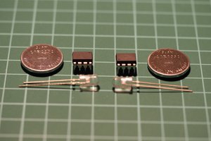
 Thierry
 Ben Delarre
 Ron O'Sullivan