Close
0%
0%

DepthIR: Object detection for the blind

A wearable device for blind people to measure distances to objects without touching them

Similar projects worth following
DepthIR is a really cheap attachment for hands (and possibly 2 similar foot attachments) to inform a blind person about the distance, size and color of objects to grasp or walk around. Each finger measures the distance to the nearest object and vibrates that finger to show roughly how far away it is. For example, a blind person could sweep their hand across and quickly sense where their dinner table is, and sweep again to sense where their cup and bowl are, without accidentally putting their fingers into their meal!

90% of the world's blind people are in developing countries, so my main goal was to make the device useful but still affordable in the 3rd world. It's designed to help people in need, rather than to buy me a Ferrari, so the whole project is non-profit and is open-source hardware & software. If the Chinese black-market makes replicas of my blind assistance device, their devices will still be helping blind people, so I'm happy to help them!

Introduction

As mentioned in my "Motivation for the project" log entry, there are already several projects that measure distance to objects for blind people using Ultrasonic sensors, but as an experienced robotics engineer, I believe ultrasonic sensors are way too unreliable. Meanwhile, there are various university labs that have tackled the same problem using highly complex 3D camera systems with powerful computers, costing many thousands of dollars just in parts. But according to the World Health Organisation, Approximately 90% of visually impaired people live in developing countries. So I'm trying to build an extremely simple and cheap Infrared-based distance measuring device for the blind, that is both good enough for real use in the First World and cheap enough for the Third World.

Infrared can be used for many purposes, and when measuring the distance to an object by transmitting some IR light and detecting the amount of IR light that was reflected back, it's usually much more reliable than Ultrasonic sensors. The standard way to measure distances of 1 or 2 feet using Infrared is to use one of Sharp's GP2Y0 analog distance sensors, such as the GP2Y0A21YK at Sparkfun for $14. That's because these devices by Sharp are quite reliable & trusted, but also because there's no cheaper alternatives! The Sharp distance sensors are similar size & price as Ultrasonic sensors and have slow data rates, but they haven't changed in decades and don't seem to have any commercial competitors, so I decided to see if I could make a similar IR distance sensor using the ultra-low-cost & ultra-small components available today. I've built my own IR distance sensors for robots in the past, so I knew it was certainly possible, I just wasn't sure if it can be done really cheap and still achieve long range and good reliability. Most IR distance sensors are only designed for a few centimetres range, whereas I want atleast 50cm range in order to allow a blind person to detect objects in front of them. My suspicion was that if designed well, Infrared distance sensors can be noticeably smaller & faster than Ultrasonic sensors and also cheaper than even the cheapest Ultrasonic sensors on AliExpress!

Detecting distance to an object using Infrared

Glossary

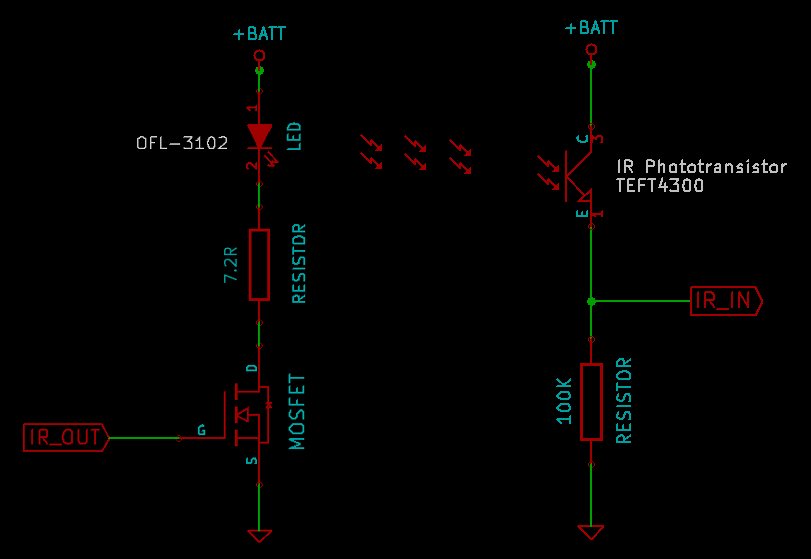
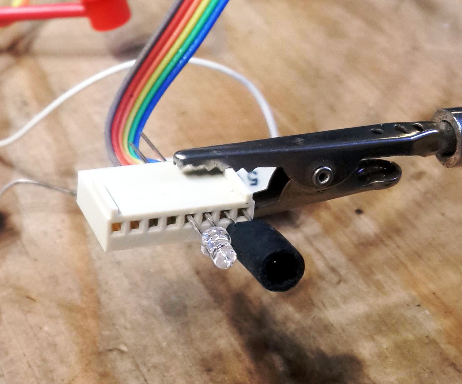
First, let's quickly list the different parts of an Infrared ("IR") system, using your TV remote as an example. Your TV remote has an "IR emitter" LED that sends out a narrow beam of invisible IR light, and your TV has an "IR photo-sensitive receiver" that measures the amount of IR light shining into it.

Method of distance detection

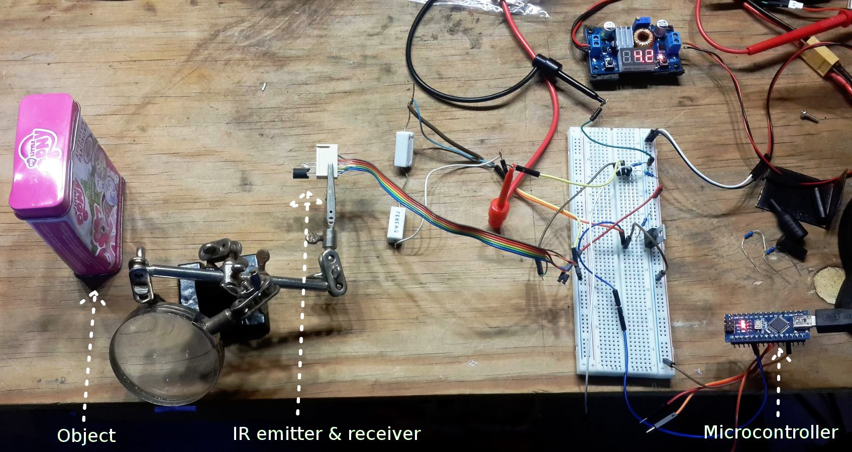
As mentioned in my "Choice of Infrared distance detection method" log entry, rather than use more complex distance measuring techniques like Time-Of-Flight / LIDAR or Projected light, I decided to simply use reflected light intensity as a way to measure distance to the nearest object. And instead of using the standard Sharp analog IR sensor, I'll be making my own version that is much cheaper, faster, longer-range & smaller.

Choice of Infrared wavelength

All LEDs (including IR emitter LEDs) generate most of their light at a certain wavelength and not as much at other wavelengths, and all Photo-sensitive receivers are most sensitive to a certain wavelength not much at other wavelengths. So the IR emitter & receiver should have signal peaks at roughly the same wavelengths. IR emitter & receiver LEDs are available in different wavelengths, from almost-red (eg: 720nm) to high-wavelength Infrared (eg: 1500nm) but most of the cheaper components are in the middle (between 840nm to 950nm). The Sun generates a significant amount of IR light at lower IR wavelengths, while artificial lights produce noticeable IR light at higher IR wavelengths. Since sunlight usually produces significantly more IR than artificial lights do, I'll use an IR wavelength that isn't produced much by natural sunlight.

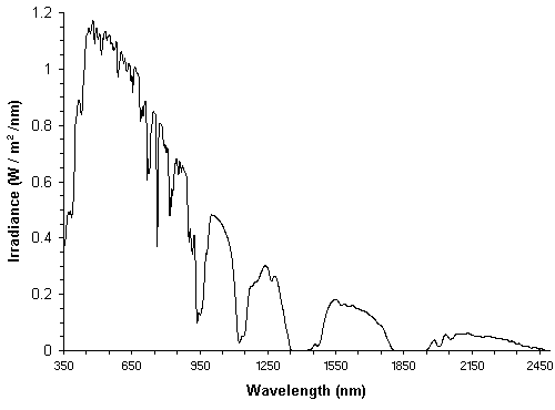
Looking at the sea-level sunlight spectrum shown in the figure above, we see that sunlight doesn't contain...

Read more »

  • Current Project Status

    Shervin Emami10/11/2016 at 01:18 0 comments

    As mentioned in the previous blog entry, the initial prototype is built & working, I was able to walk around my house (slowly) with my eyes closed just using this device! But it can definitely be improved fairly easily. I'm quite busy at the moment so I thought I'll just list the next steps needed in case I don't have enough time to work on them for a while:

    1. Reduce the amount of IR light creeping in between the IR emitter and IR receiver. Commercial IR sender-receiver pairs are separated by several centimetres and have thick black plastic and/or metal, to block all the IR light. Whereas in my current prototype I was aiming to eventually fit 2 IR emitter-receiver pairs onto a small piece of strip board to reduce space so I put them 1mm apart, and it turns out my thin pieces of black plastic tubing (pulled off an old VGA cable) aren't blocking all the IR light. Also, I realized that even if the IR emitter and receiver say they are focused within 30 degrees of the front, some IR light still happens even at 90 degrees and lots of IR light still happens at 180 degrees (ie: an LED is visible from both the front and back), but I don't currently have any light shielding at the back of the LEDs! So I need to block the IR light at the back of the IR emitter and receiver LEDs too. Once the amount of IR light crosstalk noise between the IR emitter and receiver is reduced, it should reduce the signal noise, allowing me to detect further distances since the "Signal-to-Noise Ratio" would be a lot better.
    2. Modify the code to detect further distances. Currently it detects upto roughly 50 or 60cm, any further becomes too noisy, but once I've reduced the crosstalk noise mentioned above, I'd like to detect in the 80cm - 1m range to be more useful.
    3. Build a 3D printed case, so it looks more professional and isn't as easy to damage by touch or water! I came up with an idea of building the case in 2 parts with a hinge near the middle, so it will bend around the contour of the user's hand whether they have small or large hands, and by putting the battery & charger in one part, it would potentially allow someone to own multiple battery parts that can be recharged individually off multiple USB ports, giving the user a whole set of charged batteries they can bring on a long trip.
    4. Test the battery life. I don't know if my LiPo batteries are really 240mAh or they're just claiming to be (since cheap batteries from China often do have exaggerated ratings), and I haven't measured the average power draw of the device at different states (measuring IR but not vibrating, measuring IR and vibrating at full strength) to calculate the roughly average battery life cycle.
    5. Let some real blind people use the device and get their feedback!
    6. Modify the code so it sends coded pulses, to reduce the interference from sunlight and indoor lighting.

  • Initial Prototype Built and Working!

    Shervin Emami10/09/2016 at 16:33 0 comments

    I built the initial prototype, and got it working! It doesn't work as well as I hoped, there was a lot of crosstalk noise between the IR Emitter and IR Receiver even with the 2 black tubes separating them, but they were spaced VERY close to the each (just 2mm gap), so I added a bit more space between the IR Emitter and IR Receiver to reduce the crosstalk. But I still need to reduce the noise further if I want it to have longer range. Currently it has about 60cm range, but any further than 60cm ends up looking like noise, because of the crosstalk noise. So tomorrow I'll try covering the back of the IR Emitter and Receivers, because I'm guessing that's where a lot of the crosstalk is happening.

    Anyway, here is a photo of the working initial prototype, that currently has about 60cm range!

    • Top-left section: Custom electronics I painfully made using point-to-point wiring on a piece of stripboard.
    • Bottom-left section: USB battery charger.
    • Middle section: Microcontroller.
    • Top-right section: LiPo battery.
    • Bottom-right section: On/Off button.

    Note that while I initially used a 100K Ohm resistor in series with the IR receiver, I added an extra 200K Ohm through-hole resistor in parallel to it but very close to the microcontroller analog input pin instead of being very close to the IR receiver, to reduce the effect of electrical noise, since I noticed that the wires between the microcontroller to the stripboard picked up a bit of electrical noise (probably from the vibration motor).

    Also note that I used a fairly large On/Off button for easy testing, but once I put the electronics into a 3D printed enclosure, a much smaller switch could be used. Initially I expected to use a momentary push-button instead of a latching On/Off switch, but for now I'm using an On/Off switch for easier prototyping and because the Arduino bootloader is currently taking several seconds of waiting before it boots up my code.

    UPDATE on 10th Oct 2016:

    Here is a close-up photo of the custom SMD electronics I built on a generic veroboard / stripboard PCB. As I mentioned, it is ugly, but it works for now until I get a proper SMD PCB made up!

    The 2 black tubes on the top-left are the IR emitter and IR receiver. The vibration motor is just beneath them, so that the user will feel the vibration at a similar location on their hand as the sensor is, probably making it a bit easier to map in their brain than if the vibrator was placed a few centimetres away from the sensor. The 2 black ires are ground (one black wire is only connected on one side, and is wrapped around the brown signal wire as a basic form of electrical noise reduction). The 2 yellow wires are GPIO output signals from the microcontroller to turn on the 2 MOSFETS (barely visible under the wires in the photo!). The orange wires and red wires are all connected directly to the Battery positive.

  • Arduino Code for the Initial Prototype

    Shervin Emami10/09/2016 at 16:04 0 comments

    I wrote some basic Arduino code to run the initial working prototype, based on the Test_IR_Emitter code I posted earlier. The Arduino code sends an IR pulse, measures the analog sensor readings after the pulse is reflected back, and shakes the vibration motor based on the IR signal strength. In order to reduce the effects of constant IR light sources such as sunlight or indoor lighting, I'll be sending pulses of IR and verifying that those pulses are detected. So by sending a special coded pulse signal (eg: 1 0 1 1 0 1 0), the microcontroller can verify that the received IR signal goes up & down accordingly, otherwise it would discard the signal since it would be caused by a different IR source such as sunlight. Since the IR receiver I'm using is so slow (roughly 3ms response time), sending a pulsed message takes up a lot of time, and therefore only allows roughly 50 messages per second, but that should be fast enough to feel smooth. The vibration motor is likely to have much slower response than this anyway!

    Since I wanted to test the system straight away without a complex pulse code detection system, so far I've just written some code without the coded pulses. It's available at https://github.com/shervinemami/DepthIR/tree/master/DepthIR_Arduino

    The crucial part of the code is shown here, for mapping the IR signal strength to a vibration strength (note that these values are just initial guesses and will need tweaking!):

    // Map the IR strength (between 0 to 1023) to a vibration strength between 0 to 255.
    // Since the IR strength is a steep exponential curve, we need to make sure there are
    // still some vibrations when the IR is low, but not when the signal is just noise (below 3).
    int vibrationStrength = 0;
    const int MAX_VIBRATION = 130;
    if (sensorVal > 3) {
      vibrationStrength = 60 + sensorVal * 1;
      if (vibrationStrength > MAX_VIBRATION)
        vibrationStrength = MAX_VIBRATION;
    }
    // Vibrate the finger
    analogWrite(VIBRATOR_PIN, vibrationStrength);

  • Circuit Schematic for the Wearable Prototype

    Shervin Emami10/09/2016 at 15:44 0 comments

    I drew up the circuit schematic using the free open-source KiCad EDA tool, for a single board containing all the electronics including finger attachments. As I mentioned in my previous log entry, I decided that for this first wearable prototype, I would just build 1 finger attachment and make it part of the single board.

    I designed the circuit to allow 2 finger attachments, but I'll start off only building 1 finger attachment and just ignore the part of the circuit diagram for the 2nd finger attachment.

    Here are the parts I came up with for building the initial working prototype based on parts I already had at home (cheap parts I purchased either from AliExpress in China or Element14 / Farnell in Australia when on sale):

    TOTAL COST FOR PARTS: USD$5.25

    (for a single working prototype for a single finger, ignoring the tiny amounts of hookup wire, solder and PCB stripboard used for the prototype).

    Note: The links given above are mostly for items that come with free postage worldwide from China, so that price includes shipping! But the OFL-3102 IR LED isn't available on AliExpress for free shipping, it only comes with free shipping from Element14 on orders atleast USD$30.

    The circuit can be downloaded as a KiCAD project on GitHub at https://github.com/shervinemami/DepthIR/tree/master/DepthIR_SingleBoard, or as a PDF at https://github.com/shervinemami/DepthIR/blob/master/DepthIR_SingleBoard/DepthIR_SingleBoard.pdf

    The circuit is simply made up of a Power section, a Microcontroller section, and a Finger Attachment section (duplicated for each finger).

  • Initial Working Wearable Prototype

    Shervin Emami10/09/2016 at 14:09 0 comments

    For my first wearable prototype that actually works, to build it as fast as possible, I decided not to build a separate finger attachment (containing an IR emitter + IR sensor + vibration motor + 5 wires), and just build a single circuit board that contains the finger attachment on the same board. This simplifies the wiring and housing design a lot, since I don't need to build one circuit on the palm and 2 circuits on fingers, and it doesn't need 5 wires between the palm electronics and the 2 fingers. Also, I decided to just start with 1 finger attachment for this first prototype. Once I get it working well for a single finger, it can be extended to more fingers in a later prototype!

    Since I want the device to be really small & cheap & low-power, I wanted to use an ATMEL ATtiny85 microcontroller. If I'm only going to use 1 finger attachment, the requirements on the microcontroller would be:

    • 1 x GPIO (IR emitter output)
    • 1 x Analog input (IR sensor)
    • 1 x PWM output (Vibration motor)

    This can all be accomplished with a tiny ATtiny85 even with it's 8 pins, but since I definitely want to allow 2 finger attachments in later prototypes, and possibly 3 or 4 or 5 finger attachments on a hand, so I need:

    • atleast 2 x GPIO (IR emitter output on each finger)
    • atleast 2 x Analog input (IR sensor on each finger)
    • atleast 2 x PWM output (Vibration motor on each finger)

    There are ways of using 6 I/O pins on ATtiny85, enough for 2 finger attachments, but it would be tricky, because it would mean re-purposing several of the ATtiny85's 8 pins including the RESET pin. So for this initial prototype I'm just using a standard ATmega328p microcontroller that Arduino is based on, to allow far quicker code development.

    Rather than design a custom SMD PCB and wait 1 month for it to get manufactured & sent to Australia, I decided that for this initial prototype I would use an off-the-shelf Arduino Pro Mini 328 3.3V module, an off-the-shelf LiPo battery, an off-the-shelf USB LiPo charger module, and for the custom electronics, the circuit is simple enough that I would just hack together the circuit using generic PCB stripboard / perfboard with some ugly point-to-point wiring.

  • Circuit Schematic for Simple Breadboard Experiments

    Shervin Emami10/03/2016 at 10:36 0 comments

    Now that the risky part of project is successful (ie: a cheap IR emitter & receiver with an Arduino microcontroller is enough to measure the rough distance to objects hundreds of times per second), I got a tiny vibration motor (www.dx.com/p/1027-flat-vibrating-vibration-motor-silver-5-pcs-154245) and connected to the Arduino GPIO, using the same sort of MOSFET switching circuit as I used for powering the IR LED, but I added a Schottky diode across the motor and a small capacitor, to reduce the back-EMF current & noise, since these are highly recommended when powering any motor through a MOSFET circuit. When I used a 7.2 Ohm current-limiting resistor just like for the IR LED, it only used around 20mA (compared to 40mA that the IR LED draws when using that same circuitry), but the vibrations were quite strong. So I increased the resistor to 18 Ohm so the vibrations won't be as annoying to the user.

    I've uploaded the circuit diagram (created using the free open-source KiCad package) to GitHub at "https://github.com/shervinemami/DepthIR/tree/master/DepthIR_Breadboard".

    The ports "IR_OUT", "IR_IN" and "VIBR_OUT" attach to 3 pins on any Arduino or microcontroller:

    • IR_OUT can be connected to GPIO Pin D2 that turns the IR emitter LED on when it's high.
    • IR_IN can be connected to Analog Pin A0, so Arduino can measure the IR receiver voltage.
    • VIBR_OUT can be connected to GPIO Pin D3 that turns on the vibration motor when it's high.

    The MOSFETs can be replaced by pretty much any MOSFET that's rated for atleast 0.1A Source-Drain current at 3.3V or 5V (depending on your model of Arduino). Most through-hole MOSFETs have significantly higher current ratings, but not all MOSFETs will switch on at voltages as low as 3.3V or 5V, so make sure your MOSFETs don't need more than 5V to switch on. Also be careful that all MOSFETs are very static sensitive, so you need to be careful when touching their pins, probably even more-so than when touching IC chips! The vibration motor can be replaced by any vibration motor that's rated upto 3.3V or 5V, depending on your model of Arduino. (If you use a 5V Arduino, then you could use a MOSFET that switches at low voltage such as 3V and/or a low-voltage vibration motor such as a 1V motor, it's only if you use a 3.3V Arduino that you need to be extra careful your MOSFET and/or vibration motor doesn't need more than about 3V to turn on). The Schottky diode can be replaced by pretty much any diode, but using a Schottky diode means it will give slightly more protection (to the MOSFET from the motor) than other types of diodes.

    Now that a prototype using a breadboard is working, I'm ready to start designing a PCB using tiny SMD components, so it can fit nicely ontop of the hand. Any Arduino-compatible microcontroller is fine for this project, but to keep costs & size down, I'll be using an ATMEL ATTiny85, powered directly from a single-cell LiPo rechargeable battery (ranges between 3.3V when "flat" to 4.2V when "fully charged"). The ATTiny85 microcontroller has just 8 pins on it and is extremely small compared to a normal Arduino, and the community has provided methods of running Arduino code on an ATTiny85 (with a few restrictions), so it will result in a very small wearable device compared to even the Arduino Nano!

  • Distance Measurement with an Arduino

    Shervin Emami10/03/2016 at 03:24 0 comments

    I decided to name this project "DepthIR". And I definitely want this project to be fully open-source, and even though I'm a big user of Linux & open-source software, I had a quick look at license options, and decided that I didn't want to use a GPL license on this project because GPL doesn't allow commercialization of the project. I don't expect to earn money from this project, but I don't want to stop others from building & selling it, especially if it means they are helping blind people in their region by manufacturing & selling blind devices like this. So I decided to use an Apache license, since it is an open-source license that also allows commercial use and compared to Creative Commons, it adds a bit of some legal protection as well. So I've created a project on GitHub to host the software and hardware design files for this project. (https://github.com/shervinemami/DepthIR)

    Now that I realize the phototransistor takes milliseconds not microseconds to ramp up to the full signal value, I can look at the waveform using an Arduino directly instead of using an oscilloscope! So I wrote some code to record the values from the phototransistor, to easily test different resistor values (for the resistor in series with the phototransistor) and see what sort of range I can reliably detect and how sensitive it is to the angle of the object and the color & shininess of the object. If I had more time I would do a detailed analysis, but for now I'm just going to post the Arduino code I wrote and show a few test results using a dull grey box, since it should give roughly average reflection, then I'll continue with building a working prototype.

    You can find the code for this test on Github at:

    https://github.com/shervinemami/DepthIR/tree/master/Test_IR_Sensor

    The Arduino code in file "Test_IR_Sensor.ino" will send an IR pulse and display the analog sensor readings around the time the pulse was sent. To see the sensor readings, open the Arduino Serial Monitor or any serial terminal, and set it to 115,200 baud rate. (The default baud rate of 9600 bps is too slow since we are sending lots of text!).

    The essence of the code is this:

      // Turn the IR emitter on for a short time while we measure it.
      digitalWrite(EMITTER_PIN, HIGH);
    
      // Record many analog values and keep them for later analysis.
      for (int i=5; i<512; i++) {
        // Read from the ADC. Takes around 0.1ms per reading.
        sensorValues[i] = analogRead(SENSOR_PIN);
      }
    
      // Turn the IR emitter off for a long time.
      digitalWrite(EMITTER_PIN, LOW);

    Note that the code measures the IR sensor 5 times before the loop, then turns the IR LED on, then continues measuring the IR sensor for a total of 512 measurements. The measurements take roughly 0.1ms, so the first 5 values (0.5ms) should always be small, and then if you follow it across until you find the large values, you can subtract 5 from that number of readings and then multiply by 0.1ms to get the time it happened after the IR LED turned on.

    For example, if a run has 20 small numbers (0's, 1's and 2's) and then some large numbers (4 or higher), then:

    (20 - 5) * 0.1 = 1.5

    So that would have meant there was a delay of roughly 1.5 milliseconds for the Arduino to see the IR signal.

    Note that the IR LED stays on for the whole time the analog readings are being obtained, since we are still trying to figure out how long the LED should stay on for us to get a nice measurement.

    Here are some results when the emitter LED gets around 40mA (using a 7.2 Ohm resistor):

    Without any object at all (Infinite distance):
    0 0 0 0 0 0 0 0 0 0 0 0 0 0 0 0 0 0 0 0 0 0 0 0 0 0 0 0 0 0 0 0 0 0 0 0 0 0 0 0 0 0 0 0 0 0 0 0 0 0 0 0 0 0 0 0 0 0 0 0 0 0 0 0 0 0 0 0 0

    With a box at 100cm:
    0 0 0 0 0 0 0 0 0 0 0 0 0 0 0 0 0 0 0 0 0 0 0 0 0 0 0 0 0 0 0 0 0 0 0 0 0 0 0 0 0 0 0 0 0 0 0 0 0 0 0 0 0 0 0 0 0 0 0 0 0 0 0 0 0 0 0 2 0

    With a box at 80cm:
    0 0 0 0 0 0 0 0 0 0 0 0 0 0 0 0 0 0 0 0 0 0 0 0 0 0 0 0 0 0 0 0 0 0 0 0 0 0 0 0 0 0 0 0 0 0 0 0 0 0 1 0 0 0 0 1 2 1 2 1 3 0 2 1 2 1 2 2 4 3 3 4

    With...

    Read more »

  • Initial Mockup of the Device

    Shervin Emami10/02/2016 at 15:59 0 comments

    I created an initial mockup showing roughly how I intend the device to be used. It has 2 finger attachments so you get 2 distance measurements at the same time. By using 2 (or 3 or 4) at the same time, it lets the user sweep their hand across once and already get an idea of how tall some objects are, and allows to detect objects faster, since the user doesn't need to sweep multiple times to get distances at different heights, they can sweep their hand once to get data at multiple heights.

    There's a very small pushbutton on the index finger. The device will normally not do anything, and will only be on while the user is holding that button. This allows the device to have significantly longer battery life, since electricity will only be used when the user actually wants to scan an area. I've considered the idea of getting the device to automatically turn on by itself, but I think it's better to give the user the control.

    The mockup doesn't show it, but there would be a tiny vibration motor (similar to a smartphone vibration motor) on the back of each finger attachment, so that each finger can sense its own distance and also to relay the distance back to the user.

    It's easy to think this device should be built as a smart glove, but I see 2 problems with making it a glove:

    1. When you consider that 90% of blind people are in the 3rd world, and most of the 3rd world is very hot & humid, I assume a glove is not the ideal solution for these hot & humid countries. An open-glove would be better, but I believe it can be even better by just being a small device attached to the wrist, not covering up much of the hand at all.
    2. It's important that the user can feel the vibration motors fairly well. If the vibration motors are in a glove that is loosely fitting, then the vibration motors might not be touching the user's fingers much, and so the user wouldn't feel the vibration properly and won't get the proper feedback. So either the glove should be tight on the fingers, or instead of a glove, something like a ring or open-cut ring (shown in the photo below) could be used to make sure the vibration motor sends the feedback quite clearly to each finger.

    The microcontroller & battery could potentially be placed on the back of the wrist, just like how you would wear a watch or smartwatch. But then it needs fairly long wires between the microcontroller and the finger attachments, and that means the wire is going to get caught on things more often. So in the mockup I'm attempting to place the microcontroller & battery closer to the fingers, so the wires to the finger attachments can be much shorter and less likely to wrap around objects.

  • Distance Measurement Timing

    Shervin Emami10/02/2016 at 02:00 0 comments

    RI knew the speed of light is extremely fast but I wasn't sure how fast my IR LED would reach full strength and how fast my sensor would show the full signal. If they're ultra fast (hundreds of thousands of times per second), then I could send a unique pulsed message and then decode the message, to be sure the signal came from my LED and not other signals, whereas if it's quite slow (a hundred times per second) then I wouldn't have enough time to send much of a coded signal for reliability unless if I made the device update very slowly (eg: 5 times per second, instead of 100 times per second that I'd much prefer).

    So I borrowed my friend's Oscilloscope to see the behavior of the voltages moving very quickly and in very fine detail. I put together the simple IR emitter LED circuit shown below:

    I connected IR_OUT to a GPIO pin on a 5V Arduino microcontroller, connected a 4.2V DC power source (equivalent to a fully charged LiPo battery) to +BATT, and connected IR_IN to the Oscilloscope. I placed the IR emitter LED and IR phototransistor next to each other, facing the same direction so that light from the emitter can reflect off an object and back into the receiver. Both the IR emitter LED and the IR phototransistor look like 3mm LEDs, and fit easily into common 0.1" spaced connectors. Since I wasn't sure whether I should place the IR LED and phototransistor in parallel or spaced a little apart and angled in slightly towards each other, I put them into an 8-pin 0.1" header socket and wired the connector up so I can easily plug the LED into different pins to see which one gives better response, as shown below:

    The clear LED is the IR emitter LED, and the black rubber tube next to it contains the IR phototransistor. The phototransistor actually looks the same as the LED but its black, and I put the black rubber tube around it so the receiver is more narrowly focused on the reflected beam from the emitter LED.

    Then I put a glossy object to reflect the IR light back into the phototransistor, so I could measure the time between sending a pulse and receiving the pulse. Here is a photo of the setup:


    Results of the timing test:

    When looking at the results, I was quite surprised when I saw the the IR_IN voltage on the Oscilloscope, as shown below:

    The Oscilloscope measurement of IR_IN shows that when I send an IR pulse, the IR phototransistor actually needs a fair amount of time to ramp up to the correct value! Each square block in that Oscilloscope plot is 1 millisecond (1ms) wide, so it takes around 4ms for that phototransistor to show the full signal! The Arduino analog port needs a default of 0.1ms to measure any voltage, so it means I need to leave the IR LED on for roughly 4.1ms to get the full signal! That's way too long of a duration to allow pushing an LED to its absolute current limits, so I will stick to driving the LED around its "continuous" current limit. For the OFL-3102, that's 50mA instead of the 200mA peak rating.

    But the slow speed of the phototransistor also changes the way I need to write the software. If I simply turned the IR LED on and measured the analog signal straight away, I'd be getting the voltage just 0.1ms later and so I wouldn't see any signal! So I need to add several milliseconds of delay before measuring the analog voltage of the phototransistor.

    I did some further experiments with the setup above, and noticed that the speed of the phototransistor is related to the resistor I put in series with it. If I use a 1 kOhm resistor instead of the 100 kOhm resistor, the response is much faster but it's also a much lower voltage swing, and so I wouldn't be able to get much detection range without it getting too much interference from electrical noise. I tried other values such as 10k, 20k and 40k, they behave quite similar to the 1k resistor. ie: several times faster response than with a 100k resistor but the signal is also several times weaker and so the measurement distance becomes just around 1 foot instead of 3 feet.

    Anyway,...

    Read more »

  • Choice of IR sensor

    Shervin Emami10/01/2016 at 05:21 0 comments

    Most Infrared receivers are actually 3-pin digital receiver modules that have internal circuitry to filter just a certain pulse frequency commonly used for TV remotes, and they just output an on or off signal, so we can't use them for measuring distance. We need plain analog IR photo-diodes or photo-transistors.

    Looking at several low-cost IR photodiodes and phototransistors, I purchased a few that had good potential. Besides making sure the IR receiver has a peak of roughly 940nm to match the IR emitter as explained in "Choice of Infrared wavelength", ideally the IR receiver also has a daylight-filter so that visible light does not effect the results much. (I'm not sure whether the daylight-filter is of much use when using 940nm since the sun doesn't have much 940nm radiation, but it's worth having the daylight filter just in case!). Ideally the emitter & receiver are both fairly narrowly focused instead of too wide-angled. Comparing phototransistors vs photodiodes, phototransistors tend to be more sensitive & thus better, while photodiodes might be best with an extra transistor to boost sensitivity, but since I'm trying to minimize the components on the finger where the sensor will be, and putting the transistor a few inches away from the photodiode might introduce more signal noise, my preference is a cheap 940nm phototransistor that includes a daylight filter and has narrow focus.

    Infrared receiver options at roughly 940nm wavelength (sorted by price for single-quantity):

    Device:Filter:Type:Form:Wavelength:Beam-angle:Price:
    TEFD4300FDaylightPhotodiode3mm950nm20 degUSD$0.11
    KP-3216P3C
    NonePhototransistorSMD940nm120 degUSD$0.15
    TEFT4300DaylightPhototransistor3mm925nm30 degUSD$0.18
    BPW 34 FSDaylightPhotodiodeSMD950nm60 degUSD$0.49
    SFH203PFADaylightPhotodiode5mm900nm75 degUSD$0.58

    If the receiver has a wide beam-angle, it's not such a big problem because we can easily fit a small black plastic tube around the receiver so it effectively has a small beam angle, therefore we can ignore the beam-angle column. All the wavelengths are quite close to 940nm, so we can ignore that column. I don't mind if it's a 3mm or SMD form-factor, but 3mm is easier to attach the plastic tube around, and 5mm is larger so less ideal. Daylight filter is nice, but might not be needed at 940nm. So the 3mm phototransistors have preference over the others. And since price is a big issue, the TEFT4300 seems like the best option since it's cheap, has a daylight filter, is a transistor, and is 3mm. The only downside of TEFT4300 is that its peak is at 925nm rather than 940nm, but since it's quite close there probably isn't much noticeable effect. So I'll use a TEFT4300 phototransistor as the receiver.

View all 14 project logs

Enjoy this project?

Share

Discussions

Rodrigo Loza wrote 09/27/2016 at 15:25 point

Use a webcam, a rpi3 and Deep Learning. That will surpass any system. 

  Are you sure? yes | no

Shervin Emami wrote 09/30/2016 at 13:37 point

That option certainly has a lot of potential, especially for things like object recognition with speech synthesis, but a Raspberry Pi 3 based computer vision solution won't fit on your hand or cost under $20 or have battery life of more than an hour. Whereas an Arduino with custom Infrared based solution can :-)

  Are you sure? yes | no

Rodrigo Loza wrote 09/30/2016 at 16:20 point

I agree, but this is a prototype right? You will find smaller processors later. An Intel Edison is the size of an arduino nano and very powerful + built-in wireless communication.

  Are you sure? yes | no

Shervin Emami wrote 10/01/2016 at 03:31 point

Yeah true :-) But an Intel Edison would be around 10x slower than a RPi 3 and have similar battery life of RPi of around 1 hour for a small battery, whether it's a prototype or a production system. So the options are either to build a $20 IR device that fits on your hand and has days or weeks of battery life, or build a complex $150 computer vision device that's connected to the computer & battery pack in your pocket to give you a full day of battery. My main area of expertise is actually in mobile computer vision, so I am actually planning on building such a device eventually, but I've postponed it for a few more years for when ARM dev boards will be more battery efficient and cheaper. In 5 years time a microcontroller will still be fairly similar to current microcontrollers, but ARM dev boards will be much more battery efficient and cheaper and smaller :-)

  Are you sure? yes | no

Similar Projects

Does this project spark your interest?

Become a member to follow this project and never miss any updates