 Just4Fun
I never used an ARM MCU, so I started to read a lot of documentation about this little beast, to design an homemade low cost development board to start to play with.
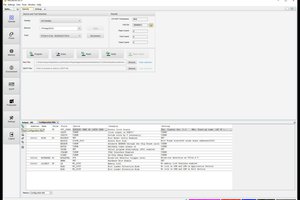
An other point of research was find the IDE to use. It seemed to me that CooCox would have been a good choice (I don't like cloud tools...).
But during some evening googling, I found this interesting place: www.stm32duino.com
These guys have brought to new life an abandoned commercial project of a company called Leaflabs, based on a couple of development boards using a STM32 ARM MCU and a "core" that enable the Arduino IDE to use them (more infos here: A incomplete short history of Arduino for STM32).
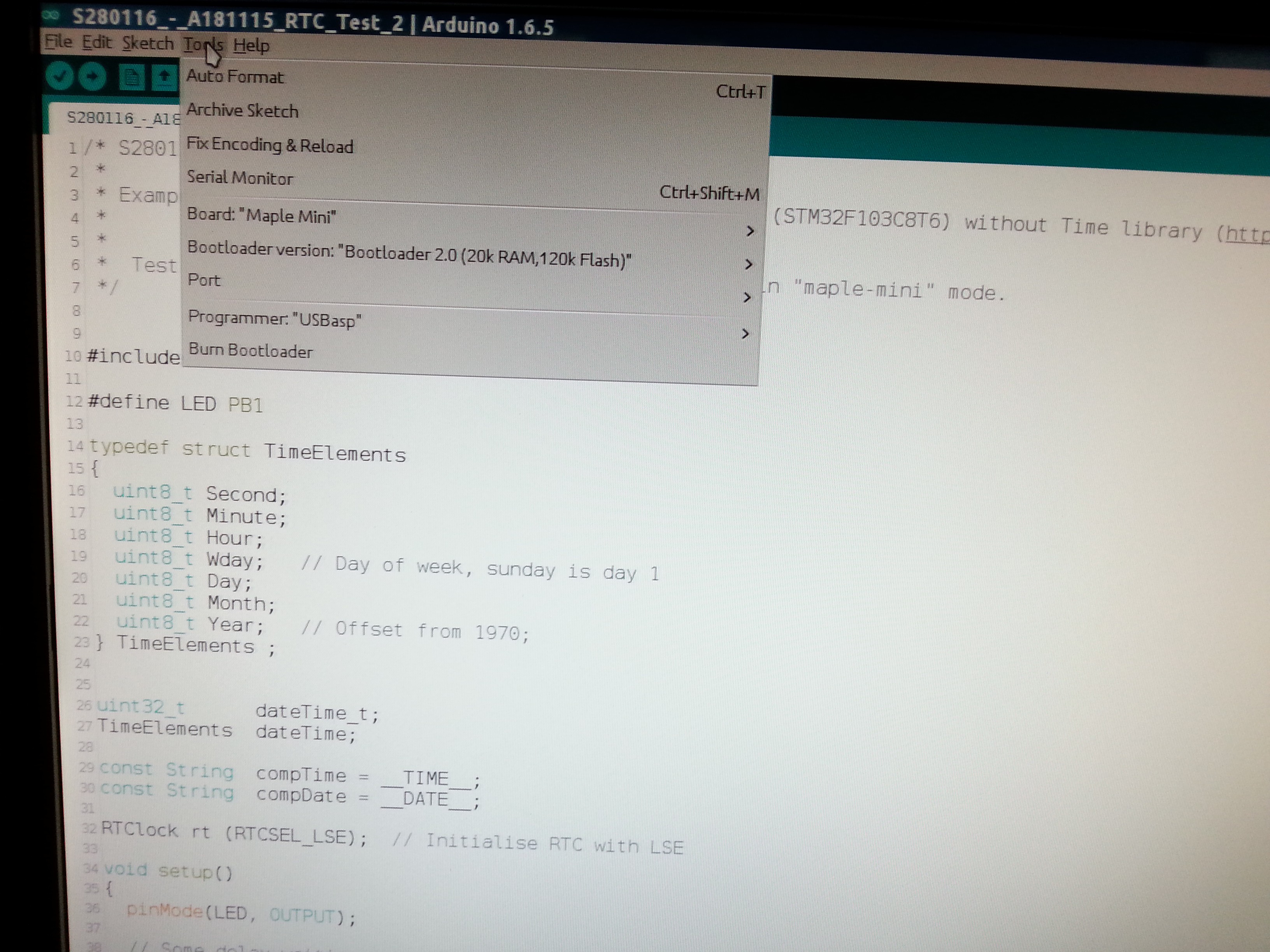
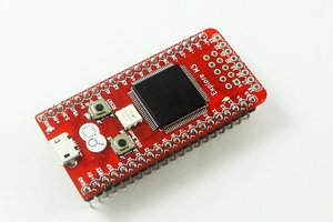
I decided that the STM32-Arduino IDE would be an handy starting point, and I started to "study" the boards used here. I found that the most used were the "maple mini clone" and the "blue pill" (see here: Supported boards), each using a different bootloader.
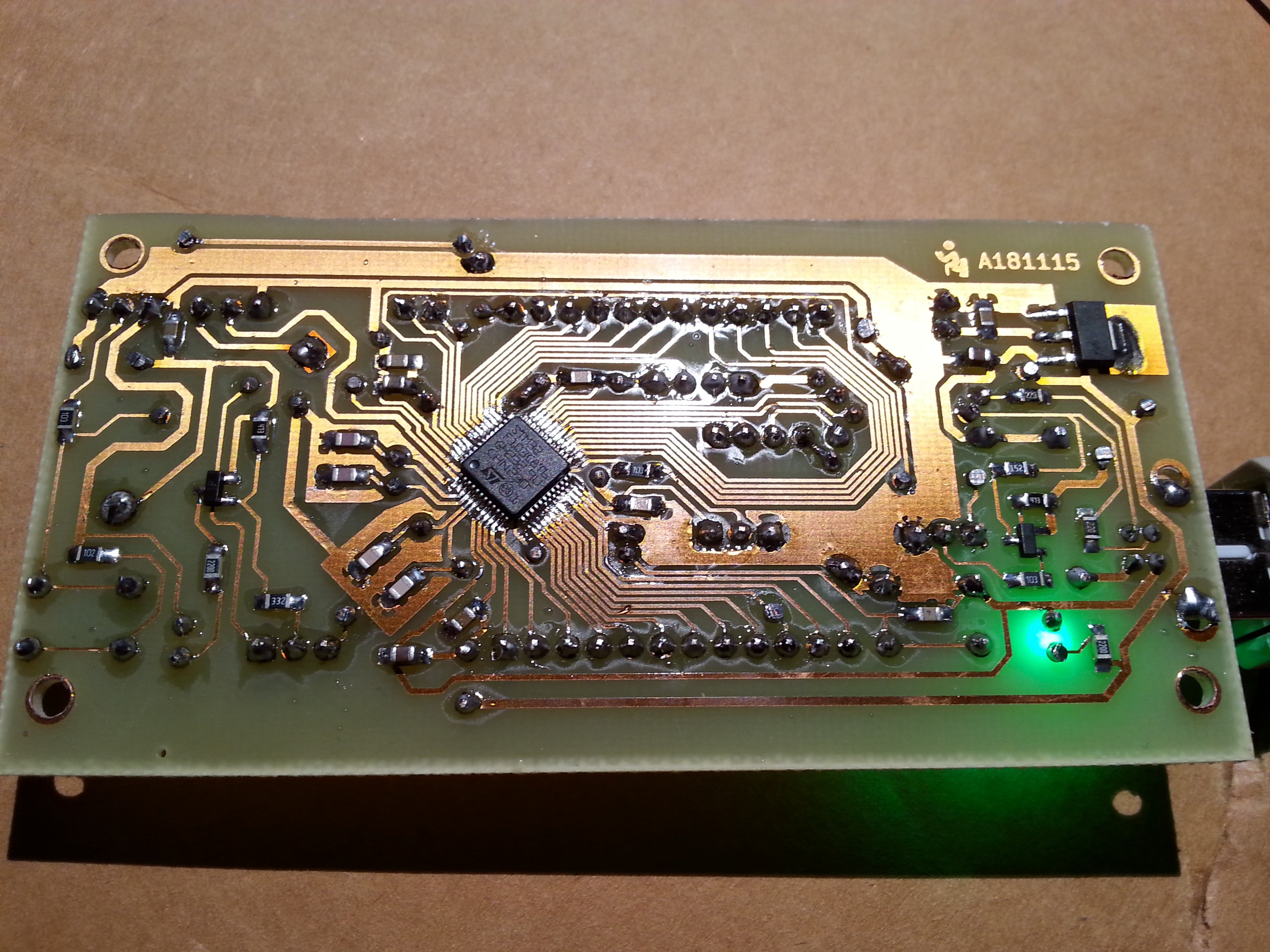
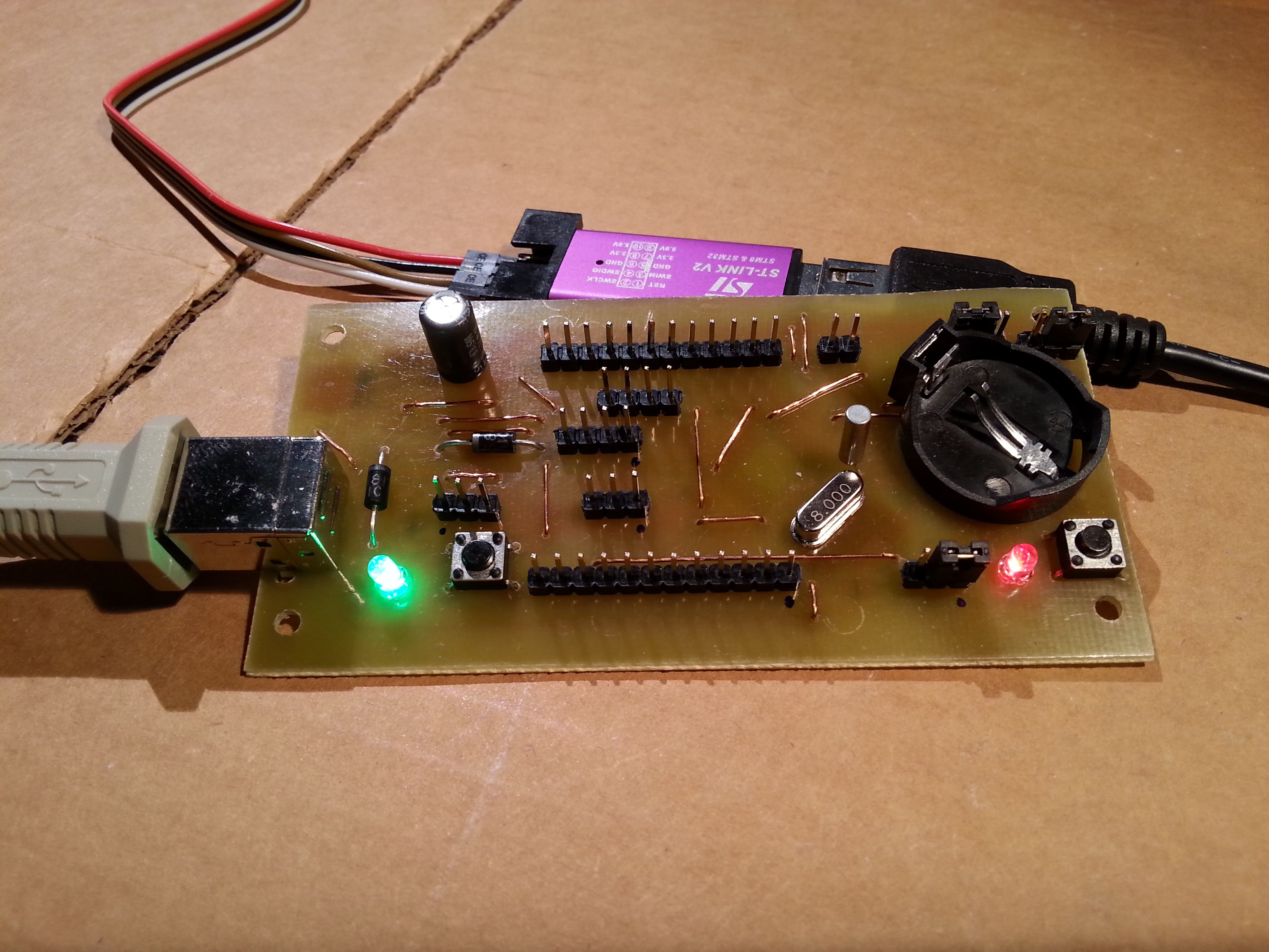
So I made one that can "emulate" both boards (changing some jumpers), just to test both bootloaders (Here the schematic: A181115-R180116.pdf. See the "Errata" at the bottom of this article!!):
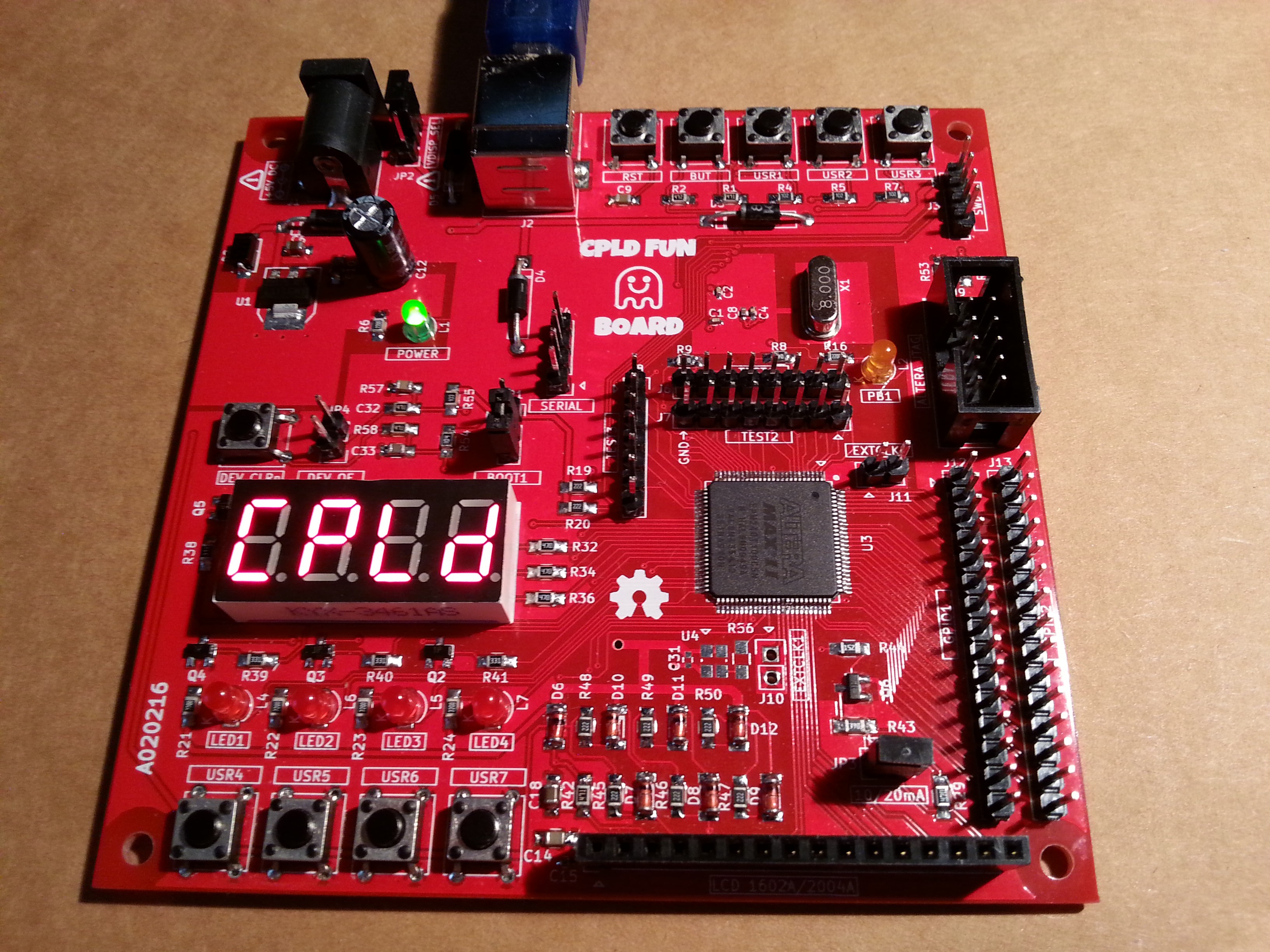
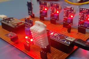
Here is an example driving a cheap 2004A LCD @5V and controlling contrast and backlight with two PWMs, two resistors and one cap (here my post on the stm32-arduino forum with the LCD wiring and the LCD demo sketch: STM32F103 driving a cheap 2004/1602 LCD @5V: controlling contrast & backlight with 2 PWMs, 2 resistors and 1 cap):
And to test the RCT here is a simple sketch that "automatically" set it from the Arduino IDE compilation time. See this my post on the stm32-arduino forum: RTC with 3.3V battery.
--------------------------
--------------------------
SCHEMATIC ERRATA (ref.: A181115-R180116.pdf):
- L2 is upside down;
- USB (J3) shield is unconnected. Better connect it to GND;
- Add an additional parallel feedback resistor (from 16 MΩ to 22 MΩ) on board to help the LSE oscillation start-up in all cases (from ST errata: STM32F10xxC/D/E Errata sheet).

 Sandeep Patil
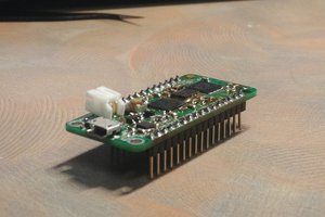
 minh7a6
Coocox is dead. To view embitz ( https://www.embitz.org ) instead coocox.
You can use the "BluePill" with this board: https://hackaday.io/project/159068-protoboard-uni-as-arduino-shield
Configure embitz: https://open-plc-com.github.io/open-plc/programming/ide/ide_ru.html
Use https://translate.google.com