Danny FR
-
Still waiting parts
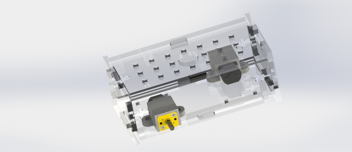
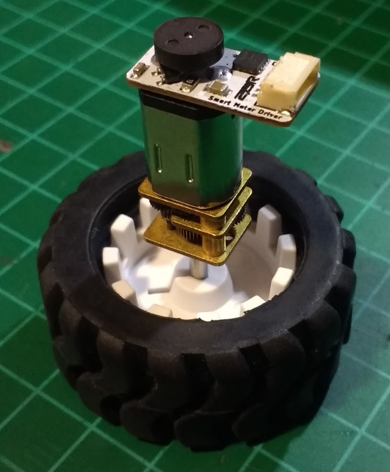
07/30/2018 at 18:51 • 0 commentsSo today I am still waiting the parts to continue the project, however meanwhile I am making a simple robot for a demonstration of the capabilities of SAMI (Smart Motor Driver). This robot is just to be a simple one, the only thing used will be the Smart Motor Driver, an Arduino and the battery.
The base is designed to use two motors and their tracks, here is a preview of how it will look.
![]()
-
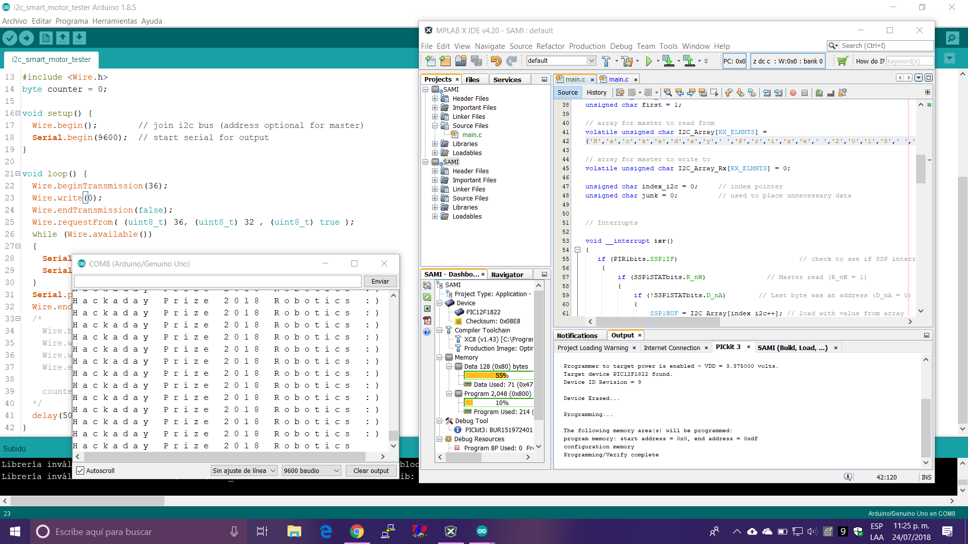
I2C working!!!! yeah
07/25/2018 at 04:36 • 3 commentsIt has been a hard time for me, so I didn't have the mood to do anything for a few days. But that is over.
I proudly present you the first successful I2C slave communication with the motor driver (SAMI) and Arduino :) Spoiler alert: an arduino library will be available to easy use of SAMI.
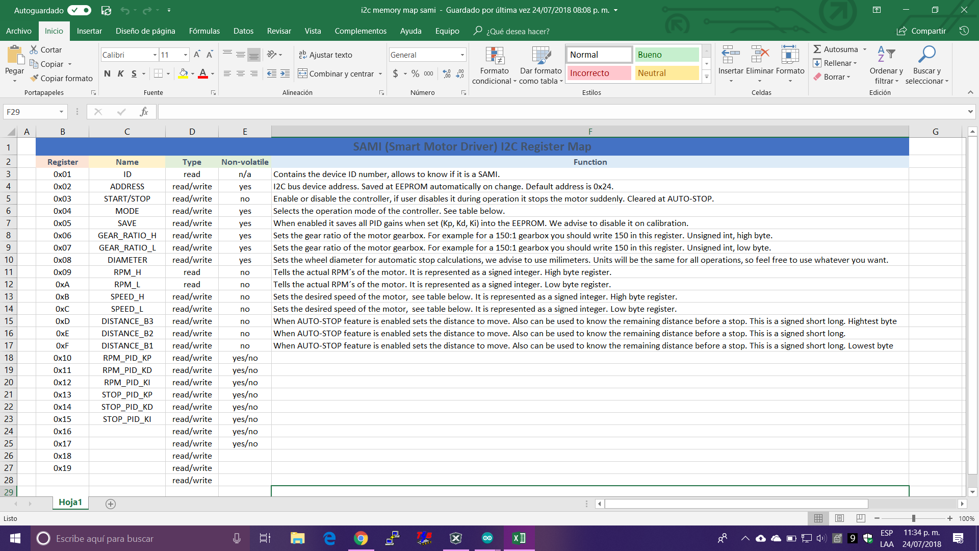
The next step will be create a register map with all necessary data to take control over the controller.
However some new components are delayed so I can't move forward until they came on the mail.
See you in a few days, thanks for reading.
-
Auto Stop first test
07/13/2018 at 18:54 • 0 commentsThis is going to be just a quick post, here you can see the auto stop implementation working, for more details about how it works you can check a previous post where I explain it. However a full post will come sooner, I am stuck right now waiting for components to continue the development.
-
Bug Fixing the PID
07/11/2018 at 03:07 • 0 commentsToday I have discovered something new, a problem that suddenly stops the motor when you change direction abruptly. So I have added a little piece of code to detect when you change direction without stopping the motor first. So now it will automatically detect when a sudden direction change is made an stop the motor using PID before executing the direction change. Now your gearings will be happy 7u7
-
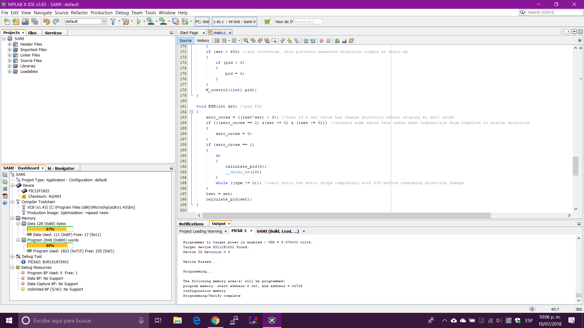
Project moved to MPLAB
07/09/2018 at 02:05 • 0 commentsToday I decided to move from MikroC to MPLAB XC8 because the code is too big for demo version of MikroC. And I want that everyone can modify and adapt the code without needing to pay an expensive compiler license. Also the microcontroller will be now the PIC12F1840 instead of the 12F1822 due to memory space available.
Github project is already updated with the new MPLAB!!! Feel free to help me improve the project and make your own version ;)
-
Mathematics behind Auto-Stop feature
07/07/2018 at 23:21 • 0 commentsOne of the fancy features of this driver is the capability of stop the motor automatically at a desired distance, making easier precision navigation in a robot or maybe other kind of applications. Like a conveyor belt or an actuator, just let your imagination fly. Applications are limitless, trust me ;)
Sounds good right? But it will not happen magically, we need to do the math. We need to obtain an equation that allows us to convert that desired distance into how many pulses the motor Hall sensor should give us to achieve the goal and stop the motor just there.
So let's get started, shall we? Normally robots use wheels and wheels are basically circles with a perimeter, so every time the wheel makes one turn the robot moves an equal distance to this perimeter. This is the key to solve the problem, if we know the perimeter of the wheel and the gear ratio of the motor we can calculate how many turns the motor should do to move the robot certain distance. Said this we have the main formulas involved.
But this way it doesn't help, we a different approach where the perimeter is the desired distance we want. So we really need this one, so Perimeter will be equal to distance.
This formula applies just for the wheel. Now to obtain how many turns the motor should turn we just need to multiply it by the gear ratio.
Remember that our Hall sensor will detect 3 pulses (or steps) per each turn of the motor, this is where that constants appears in the play. So we finally have:
Where G is the gear ratio of the motor, d is the desired distance we will move and D is the diameter of the wheel. That's it, we enter the distance and we get how many pulses our Hall sensor should detect before it stops the motor. Easier than you thought, right????
![]()
Just for reference, if we have a 45mm diameter wheel a fully turn will be equal to 141.4mm. This is the distance the robot will move for each wheel turn. With a 150:1 gear ratio motor it means that for every one complete turn of the wheel the motor needs to turn 150 times. If the Hall sensor detects 3 pulses for every motor turn we obtain 450 pulses for every turn of the wheel. So if we divide the diameter by the pulses we obtain the resolution. So our robot will be capable of moving an amazing super precise steps of 0.314mm!!! Cooooool...well in an ideal world, we will make some testing and explain more about the "ideal world" in the next post ;)
-
Fully working PID algorithm
06/26/2018 at 01:55 • 2 commentsFinally I come with a fully functional PID algorithm ready to rock :)
Here you can see an acceleration/breaking ramp test, of course you can adjust the response by tuning the gains (Kp, Kd, Ki) to your own preferences. Slow responses may be useful to avoid stripped gears at sudden movements, also when you have a tall inestable robot that can flip upside down. And when you have a stable robot you can reduce response time to have faster movement transitions. A perfect gain adjust will let you have the best of both worlds.
Remember that all the code is available on GitHub, I just used the standard PID equation with some tricks to scale the values to proper ones for backward and forward rotation with same equation. Not so much an interesting thing to discuss ;)
void calculate_pidM(int set) //PID calculation function
{
    float error = 0;
    float pid = 0;
    error = set - I2C_buffer.data.RPM; //calculate actual error
    pid = error * I2C_buffer.data.RPM_PID_KP; // calculate proportional gain
    accumulatorM += error; // calculate accumulator, is sum of errors
    pid += I2C_buffer.data.RPM_PID_KI*accumulatorM; // add integral gain and error accumulator
    pid += I2C_buffer.data.RPM_PID_KD * (error - lasterrorM); //add differential gain
    lasterrorM = error; //save the error to the next iteration
    if (pid >= 1023) //next we guarantee that the PID value is in range
    {
        pid = 1023;
    }
    if (pid <= -1023) {
        pid = -1023;
    }
    M_control((int) pid);
}
In the next post I will publish about the auto-stop at defined distance mathematics starting from the wheel diameter and gear ratio.
-
Having troubles with PID control
06/24/2018 at 04:51 • 0 commentsTuning the PID with the motor running forward was easy but transition to backwards was a completely whole new pain in the ass. It works now both directions flawlessly, however there is still a bit of overshoot only when moving backwards starting at 0 RPM because it runs forward a little bit and then in the right direction while the system compensates the error.
In the next entry I will explain how I fix the issue and also how to do the PID control like a pro using only simple and standard equations ;)
-
How it calculates motor speed
06/24/2018 at 04:40 • 0 commentsIn this log I will explain how the microcontroller calculates the motor speed in RPM for be used later in the PID algorithm (spoiler alert, that would be a future topic) .
First let's take a look to that part of the code, shall we??? We will be using MikroC
void interrupt() iv 0x0004 ics ICS_AUTO //interrupts
{
 if (INTCON.f0 == 1 && IOCAF.f4 == 1) //interrupt on change on RA4 triggered
 {
  INTCON.f3 = 0; //disable on change interrupts
  counter ++;  //increment counter one in one
  IOCAF.f4 = 0; //clear interrupt flags
  INTCON.f3 = 1; //enable on change interrupts
 }
 if(PIR1.f0 == 1) //timer1 interrupt, called every 65.536ms
 {
  INTCON.f3 = 0; //disable on change interrupts
  T1CON.f0 =  0; //stop timer1
  rpm = (counter * 300)/gear;  //calculate rpm  (multiplied 15 interrupts in 1 second, divided 3 encoder interrupts per lap, multiplied by 60 to convert to minutes, divided by gear ratio)
  counter = 0;  //clear counter
  if(LATA.f0 == 0) //if motor is running backwards we just turn value negative
  {
    rpm = rpm *-1;
  }
  INTCON.f3 = 1; //enable on change interrupts
  PIR1.f0 = 0; //clear interrutp flag
  T1CON.f0 =  1; //start timer1
 }
}
The first thing you can see is that all process is handled using interrupts, so the microcontroller can do other things and then update once a while. The code is pretty straightforward, we use the pin state CHANGE interrupt to count up every time the hall sensor detects a change in polarity from N to S, easy right?
Next we use a timer to interrupt every 65.5 ms and do the math, we just use the equation:
where counter is the number of times the hall sensor has changed polarity from N to S and we multiply by 300 (we divide by 3 changes from N to S are equal to one turn of motor shaft, then multiply by 15 because is the number of timer interrupts that should happen in 1 second and finally we multiply by 60 to convert to minutes). After that we now how many turns the motor will do in one minute(aka RPM), now we only divide it by the gear ratio attached and we have the RPM in the output shaft of gearbox.
As you can see is easy to make the RPM measurement in second plane, obviously the value will get updated every 65.5 ms. Not so fast, but consistent enough to run a PID algorithm and also let free time for other process.
-
Tunning PID
06/17/2018 at 04:19 • 0 commentsNow the PID function works perfectly, time to tune kp, kd and ki for this specific motor without load and continue the development. Tunning was done just experimenting with the gains, I will look in providing some sort of auto tune method for easier use.
Smart Motor Driver for Robotics
This motor driver is able to control a motor using PID by I2C. Taking precise control of a motor have never been so easy.