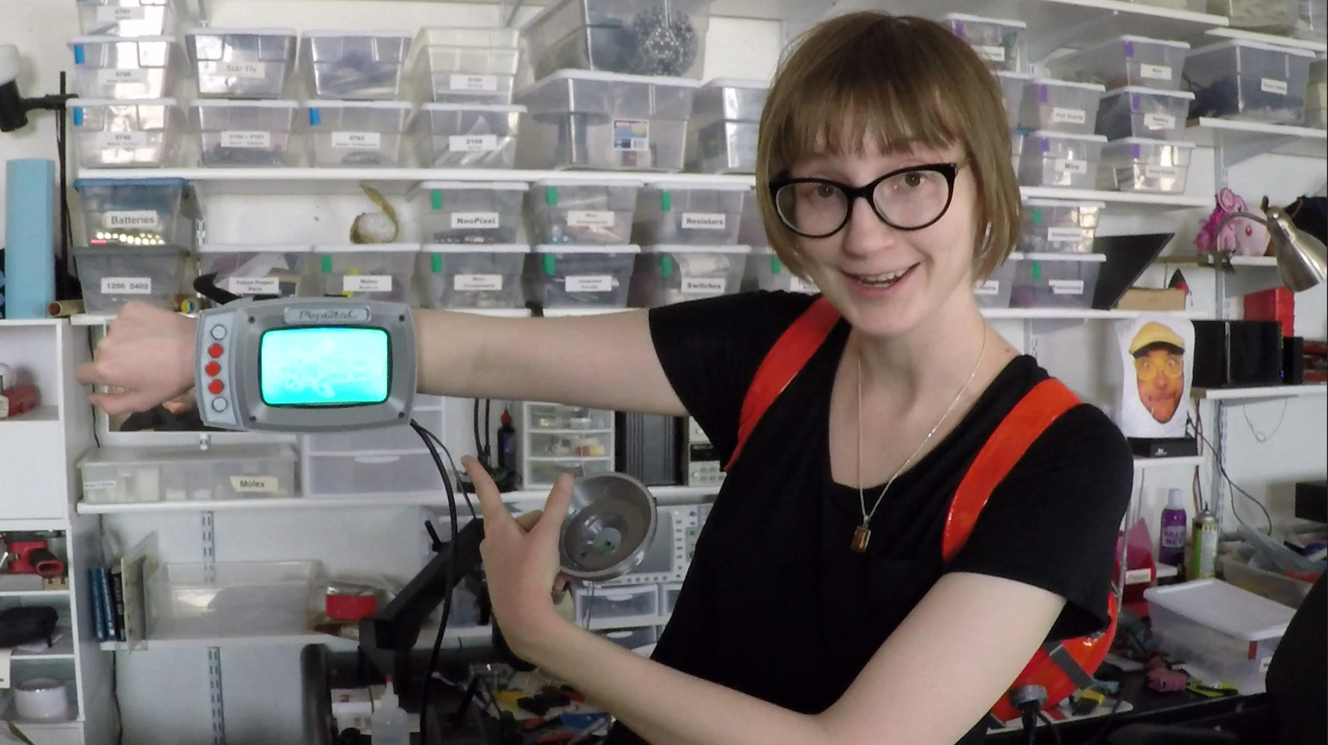
Close
0%
0%

SHE BON

! a platform for sensing and indicating human arousal !

Public Chat
Similar projects worth following
We should be more comfortable talking to one another about sexuality and intimacy. To help normalize a general dialogue about sex, I'm creating a series of wearables that will sense and indicate human excitement using a variety of sensors as input... and some crazy mechanical nonsense of my own design as output.

The platform I have designed for this wearable project is open source, so I invite you to participate as well, whatever your gender may be. My goals:

1. I hope that if you choose to log and studying your own bio-feedback, the act of focusing attention on new aspects of your body will help you know yourself better than ever before.

2. I hope that if you choose to create your own wearable augmentation to indicate your physical status, you shed any stigma that may have ever been associated with your sexual nature!

3. I want humanity to take ownership over its most basic right, without shaming, victimizing, or feeling embarrassment.

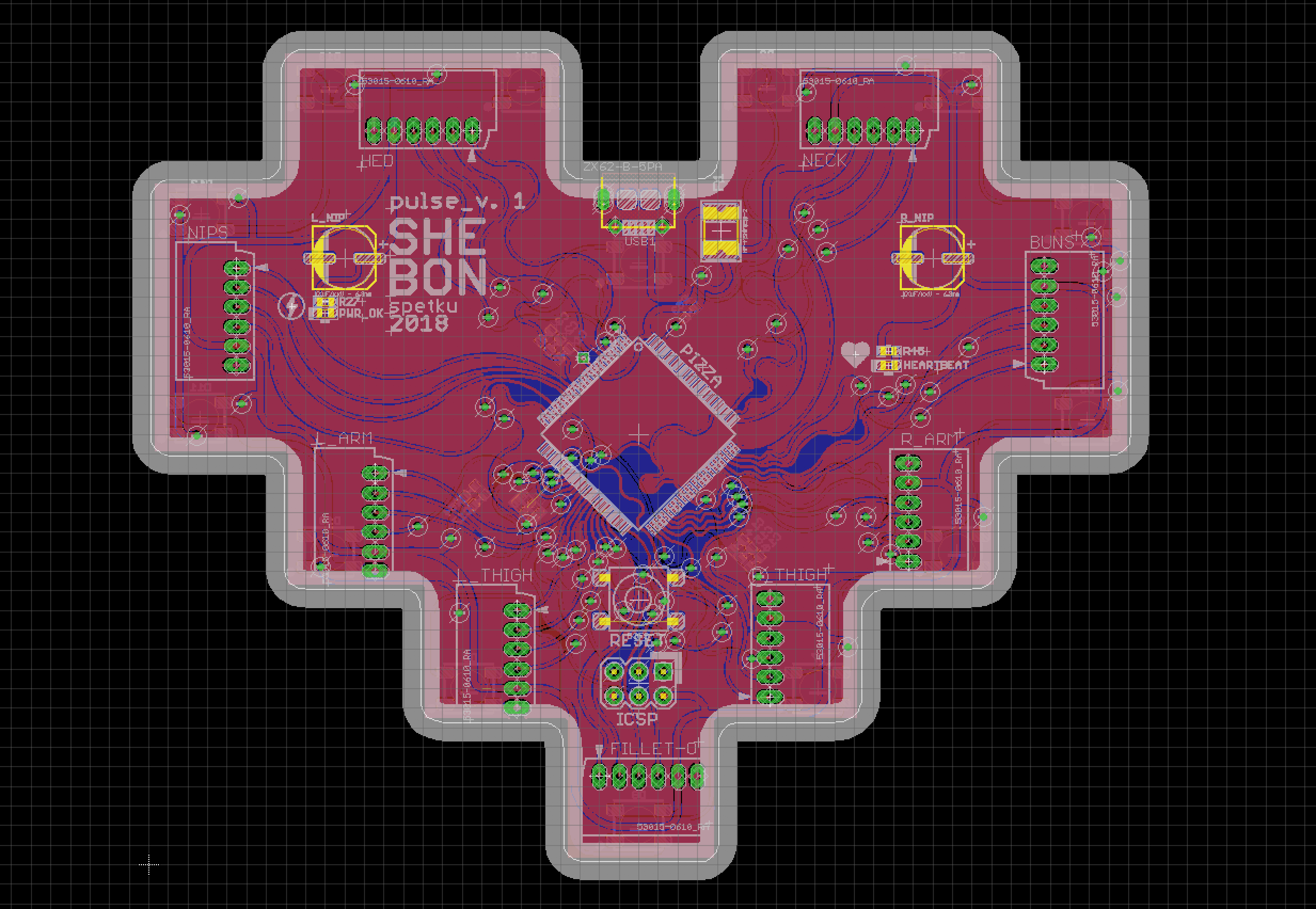
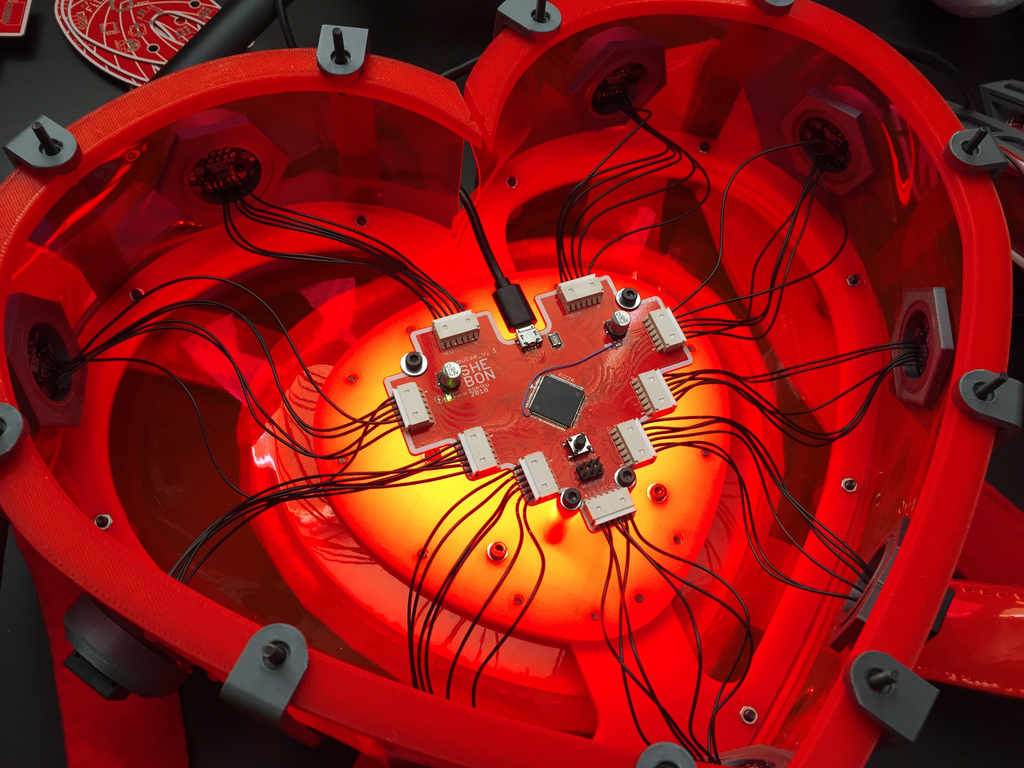
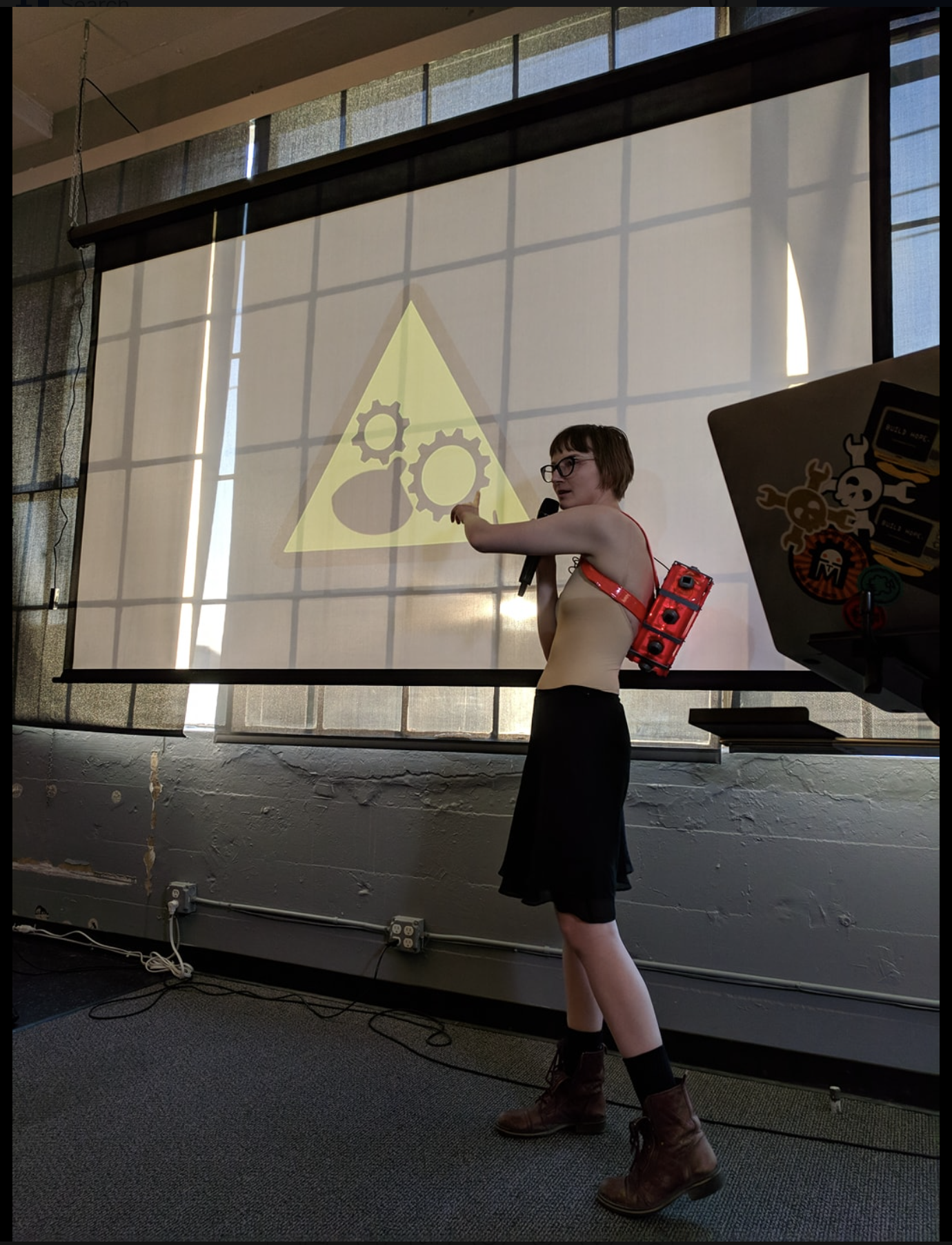
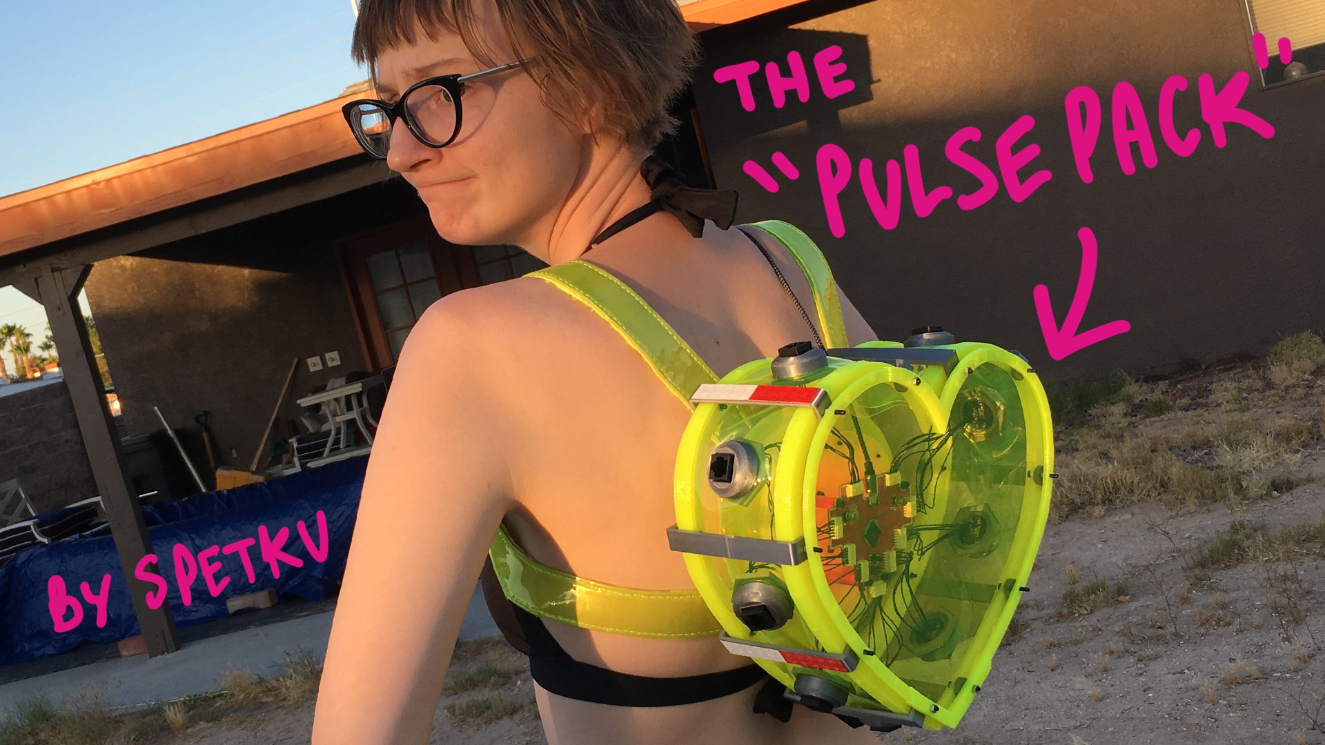
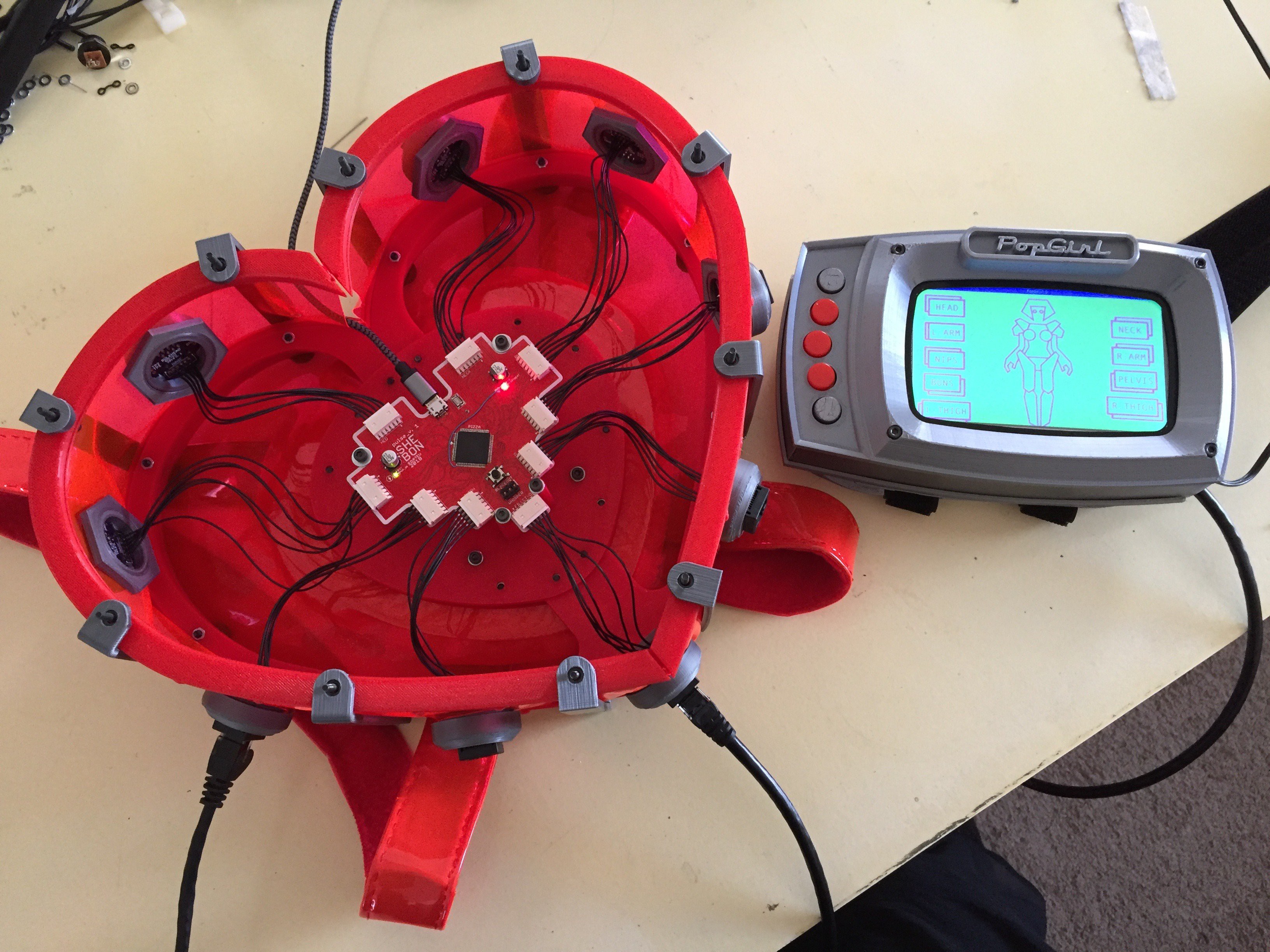
Hi everyone! This spring I've committed to make myself "a suit of amour" that will indicate my physical status... particularly my level of excitement. My intention is to manipulate a multitude of sensors in order to track my physical status, so that when I reach a heightened state, some other mechanical wearables will actuate to indicate when this threshold is reached!

As a creator of technology and physical things, I would like to live in a world where our bio-data can be used to communicate what is otherwise invisible... and as a result, grants us humans the ability to express our individuality in new and unique ways.

I wish to wield technology in order to make life more interesting for myself, and everyone I interact with. If you would like to accomplish the same thing, I welcome you, fellow maker/hacker, to talk to me about your thoughts and reflections. Lets make the world awesome by choosing to know ourselves, and each other better. <3

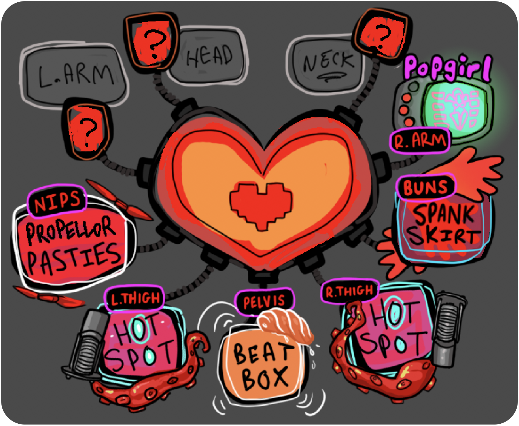
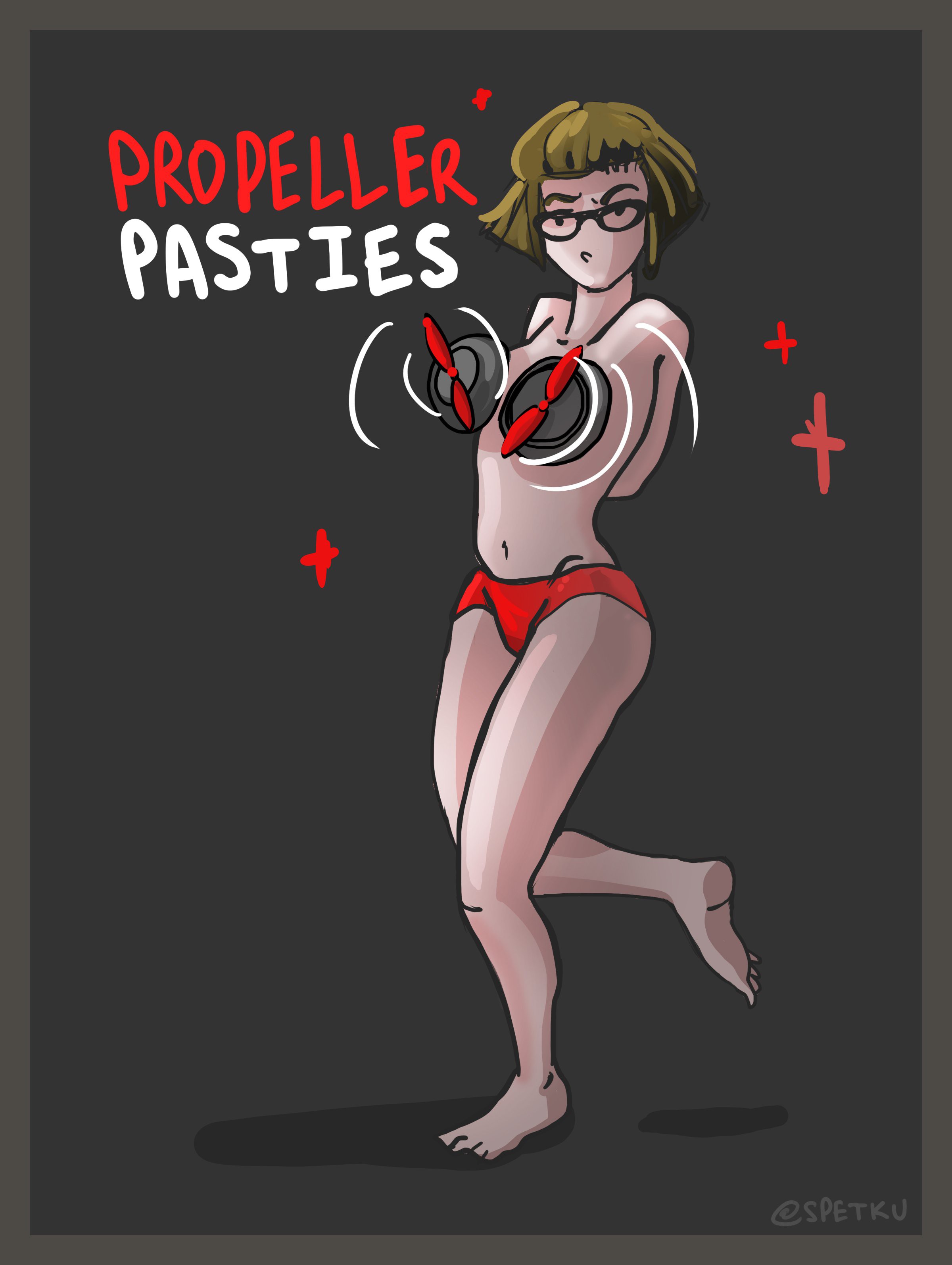
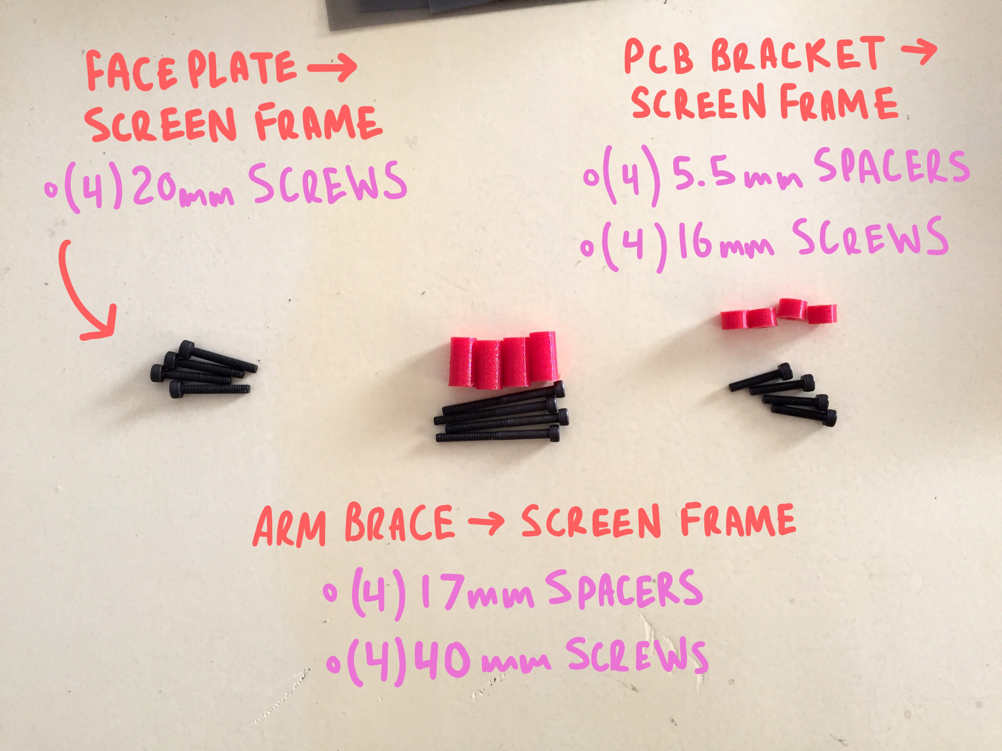
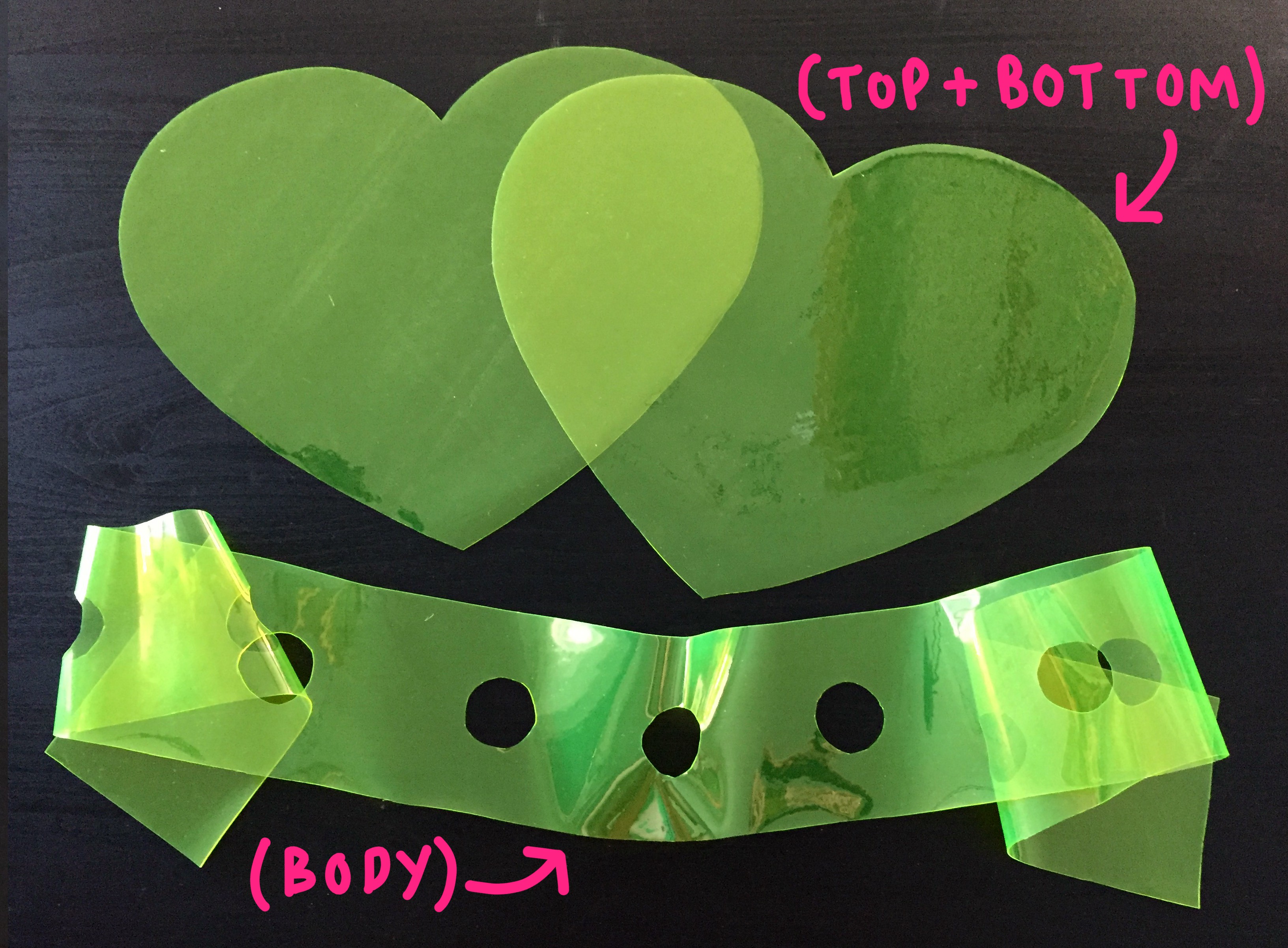
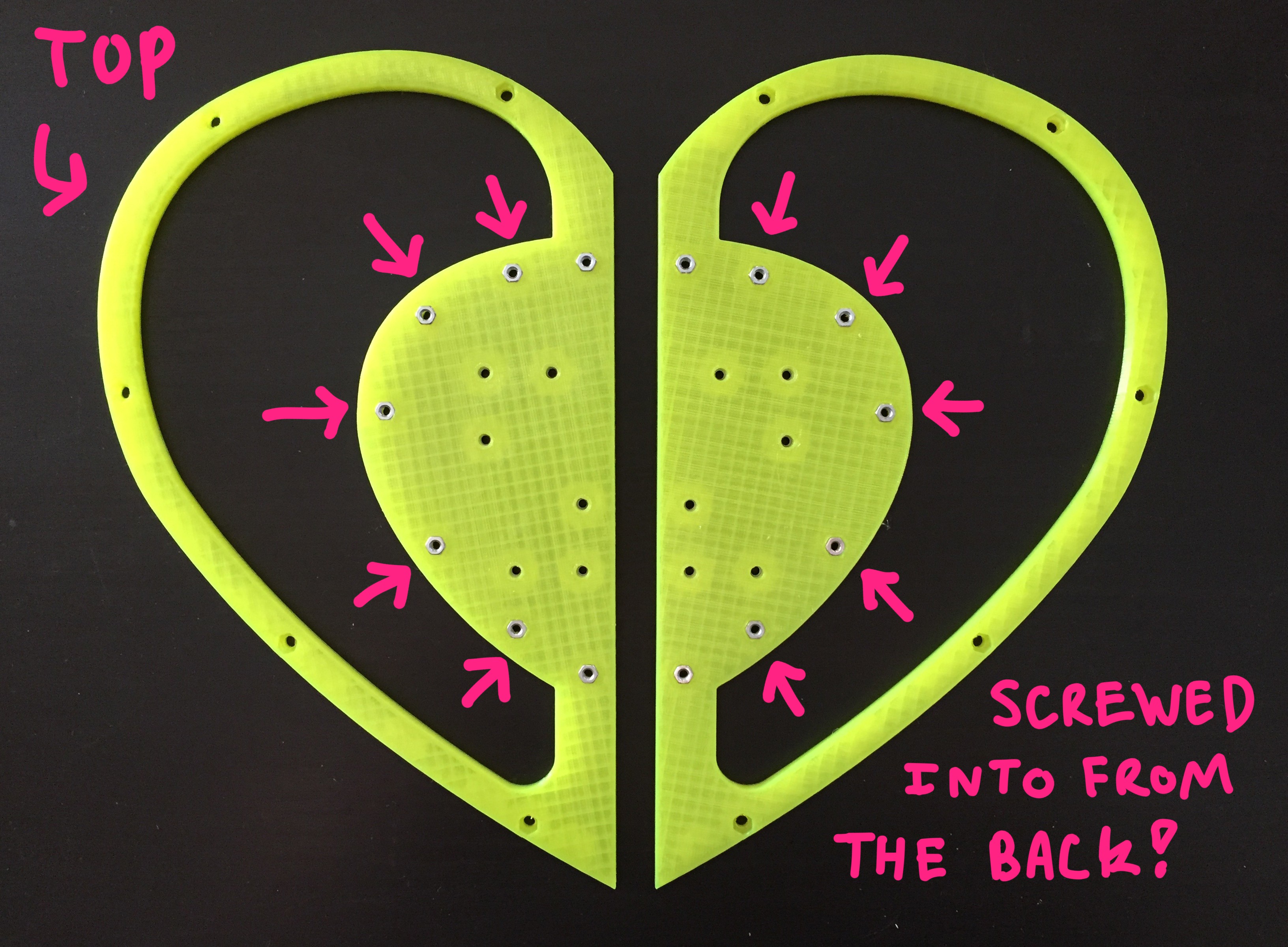
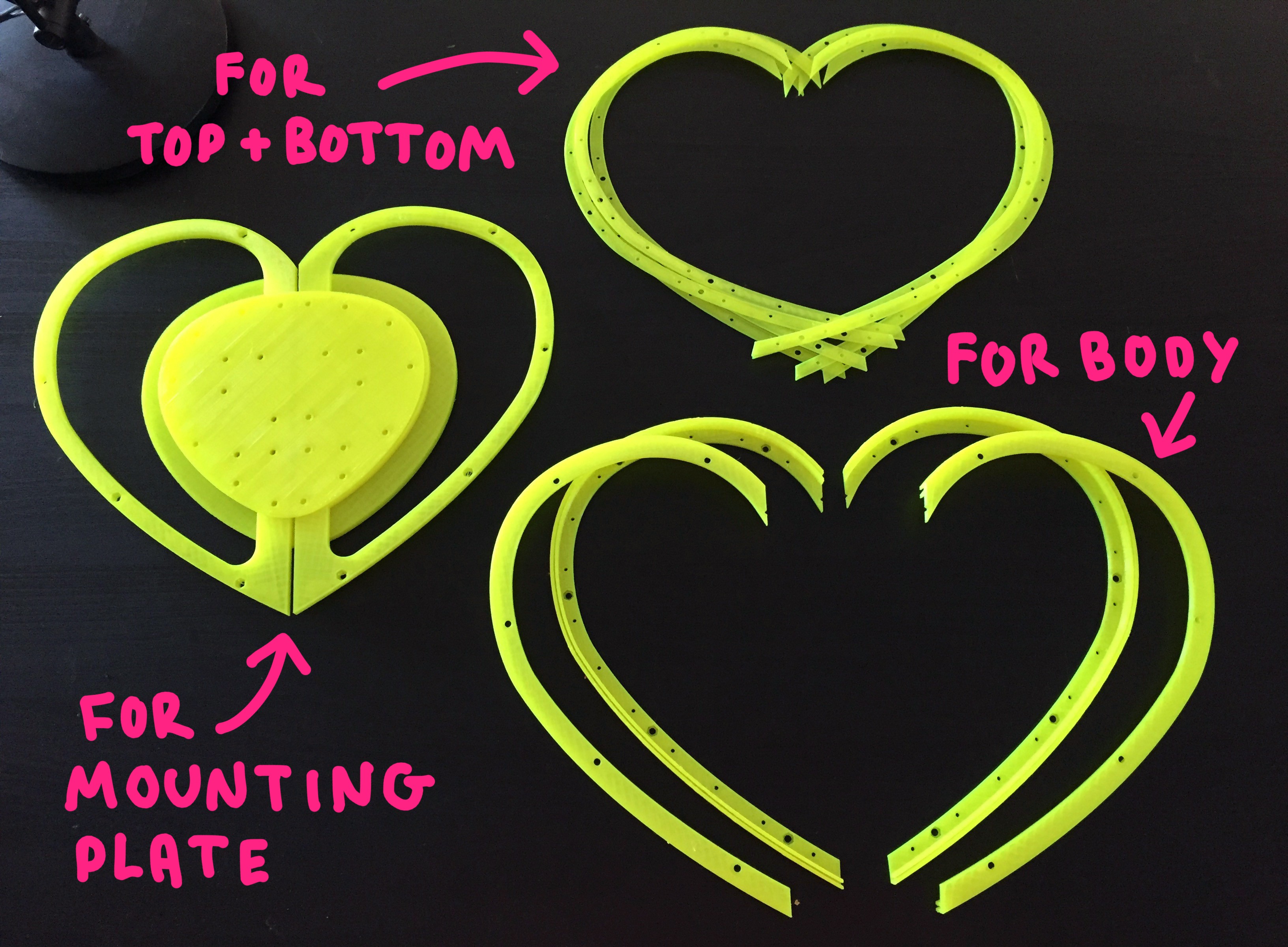
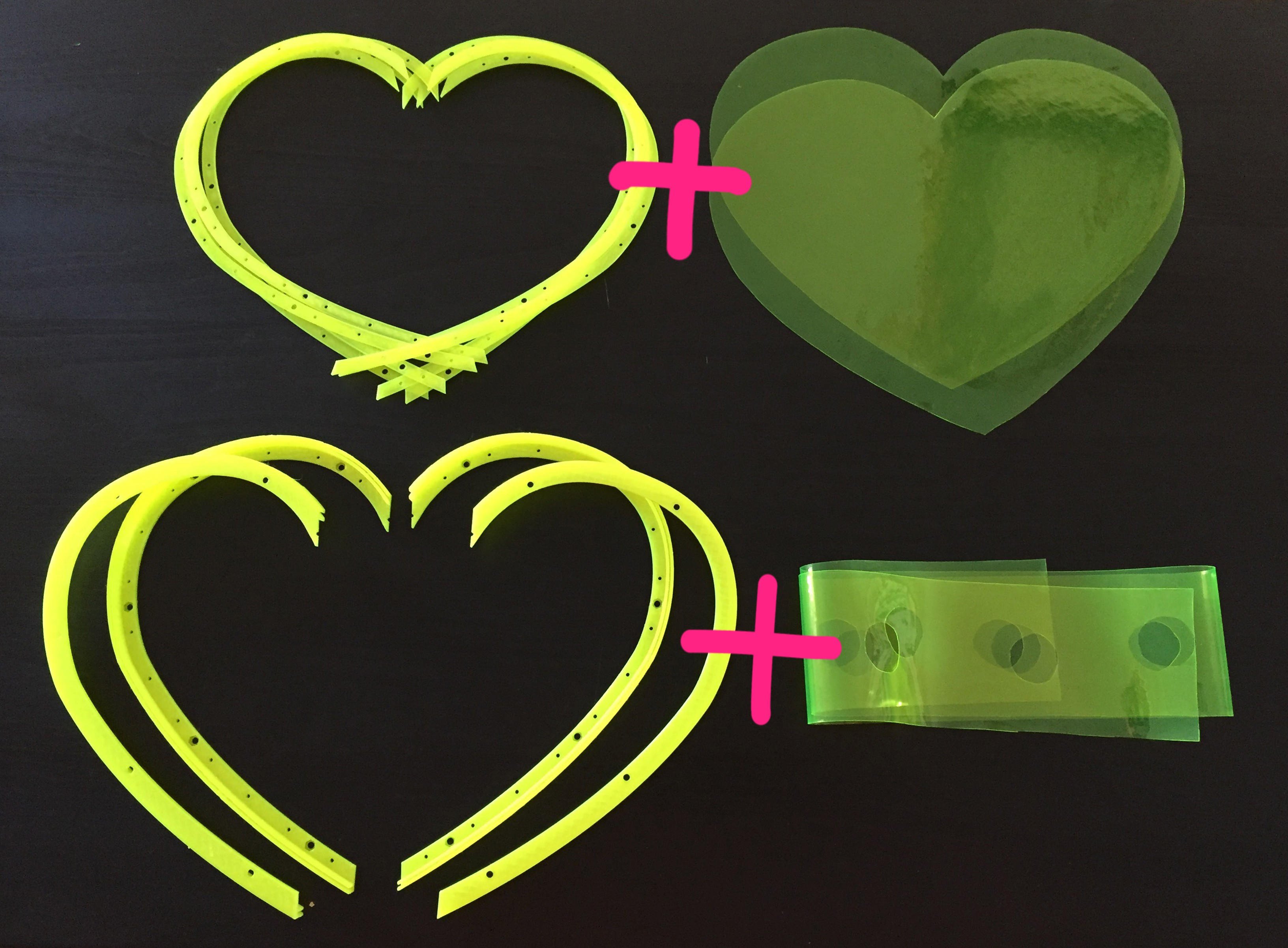
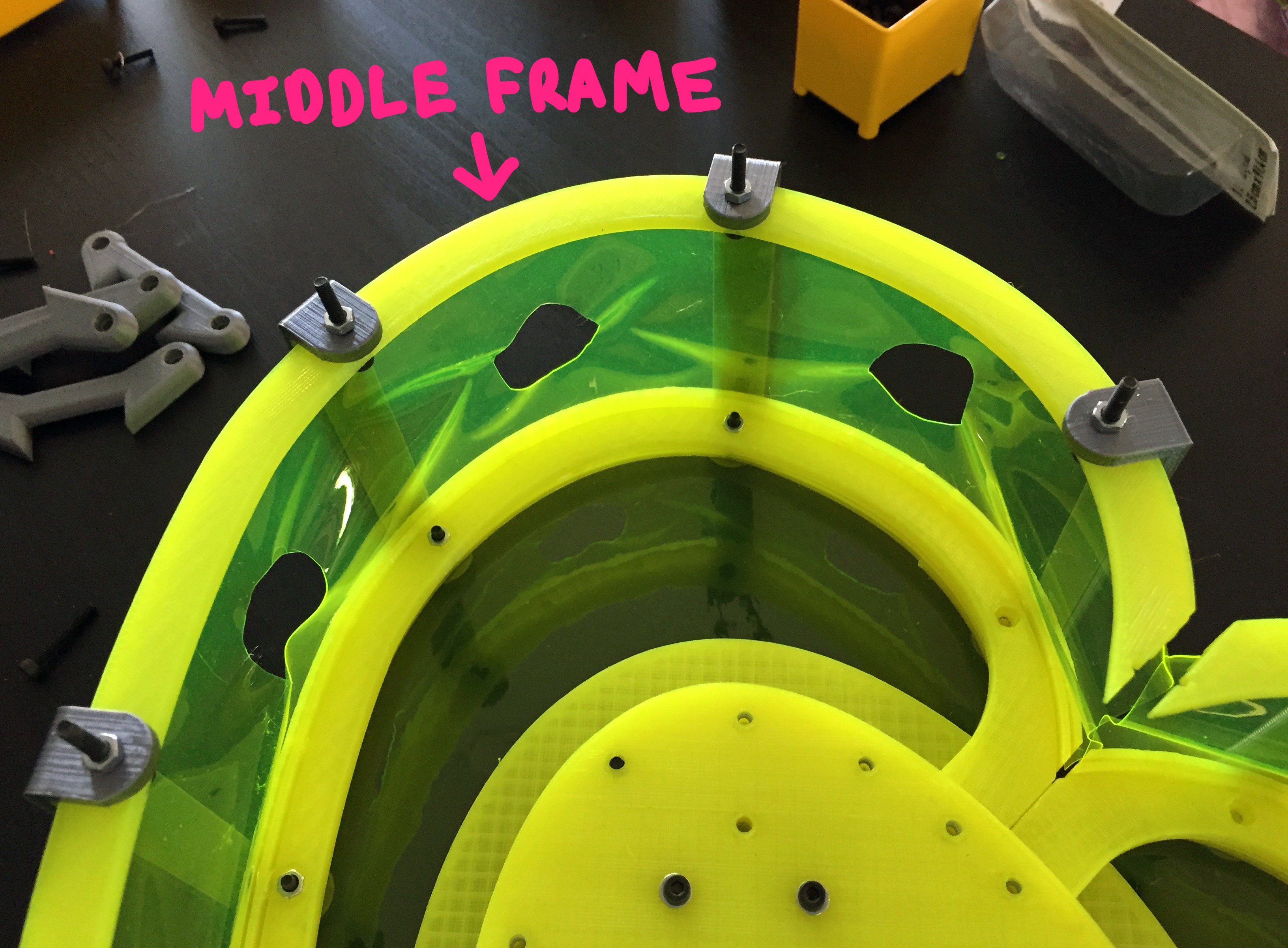
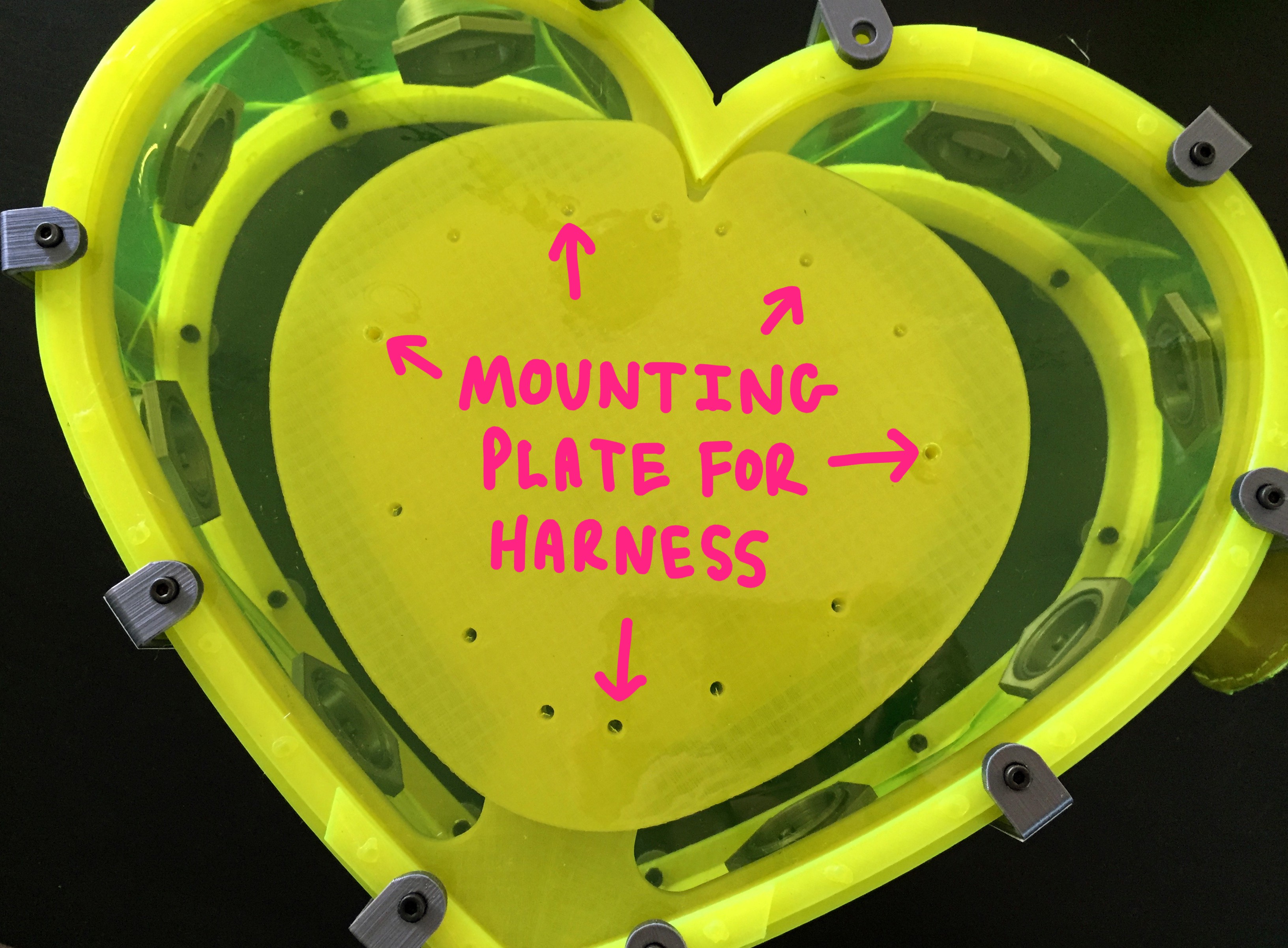
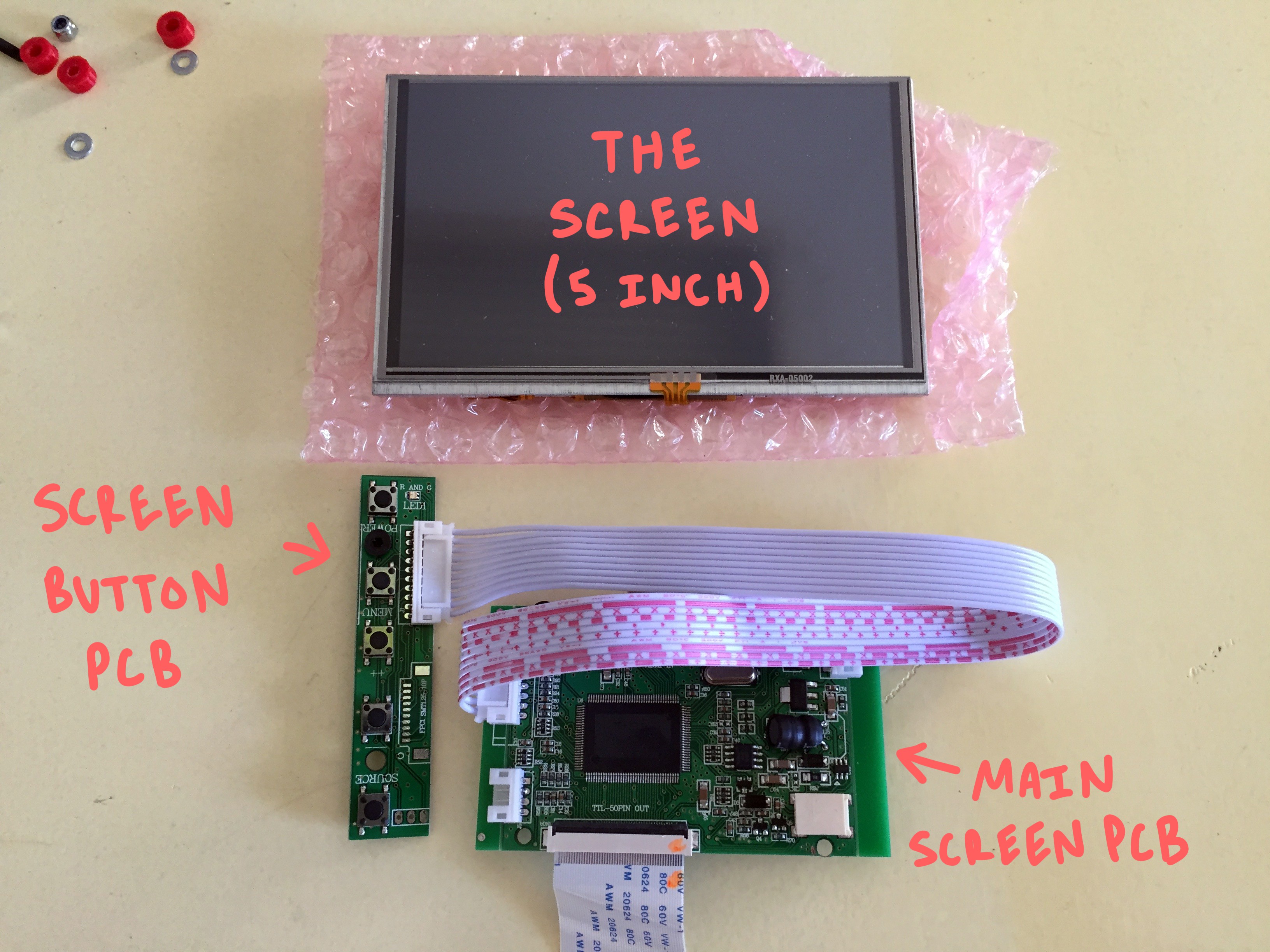
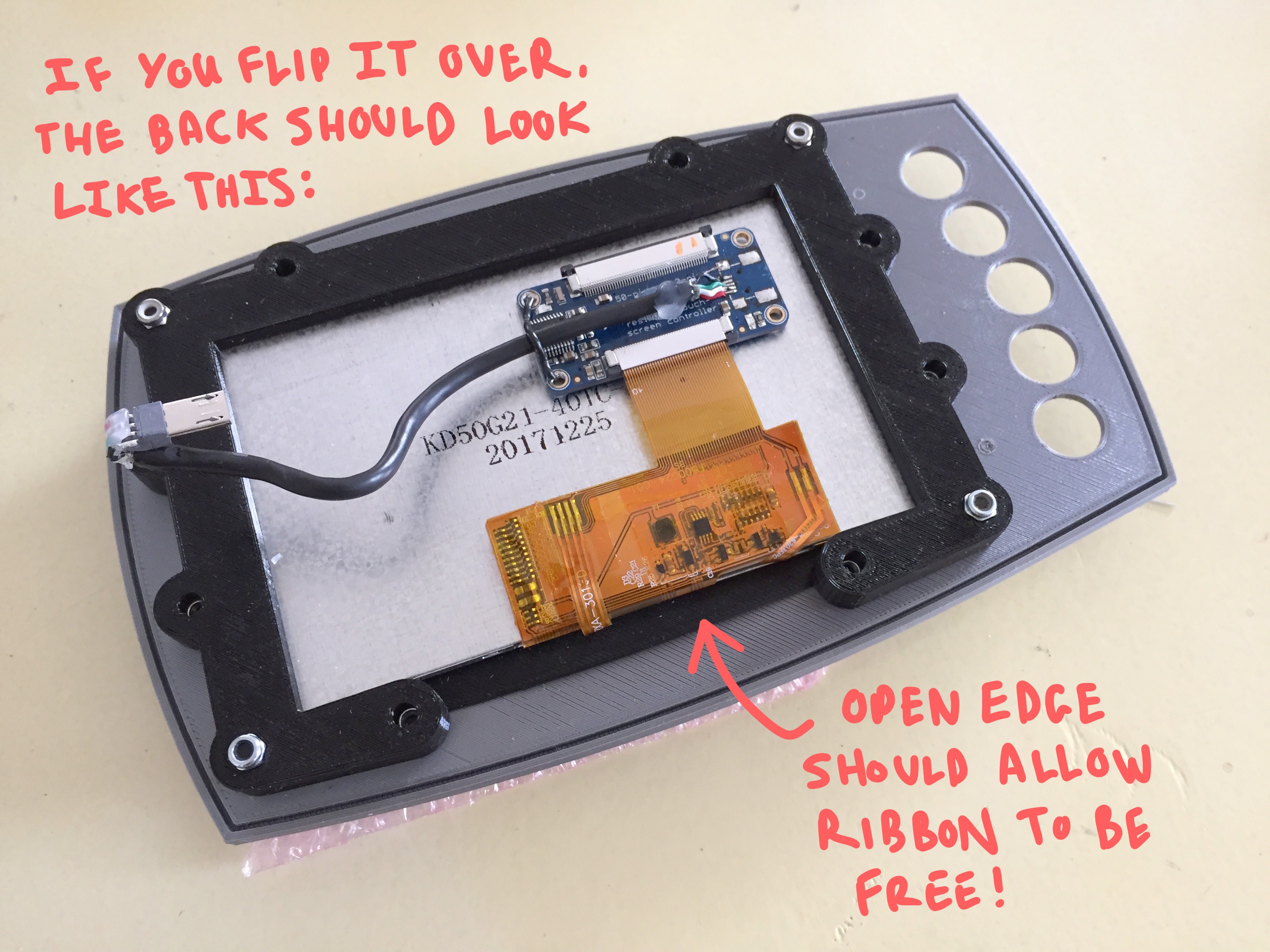
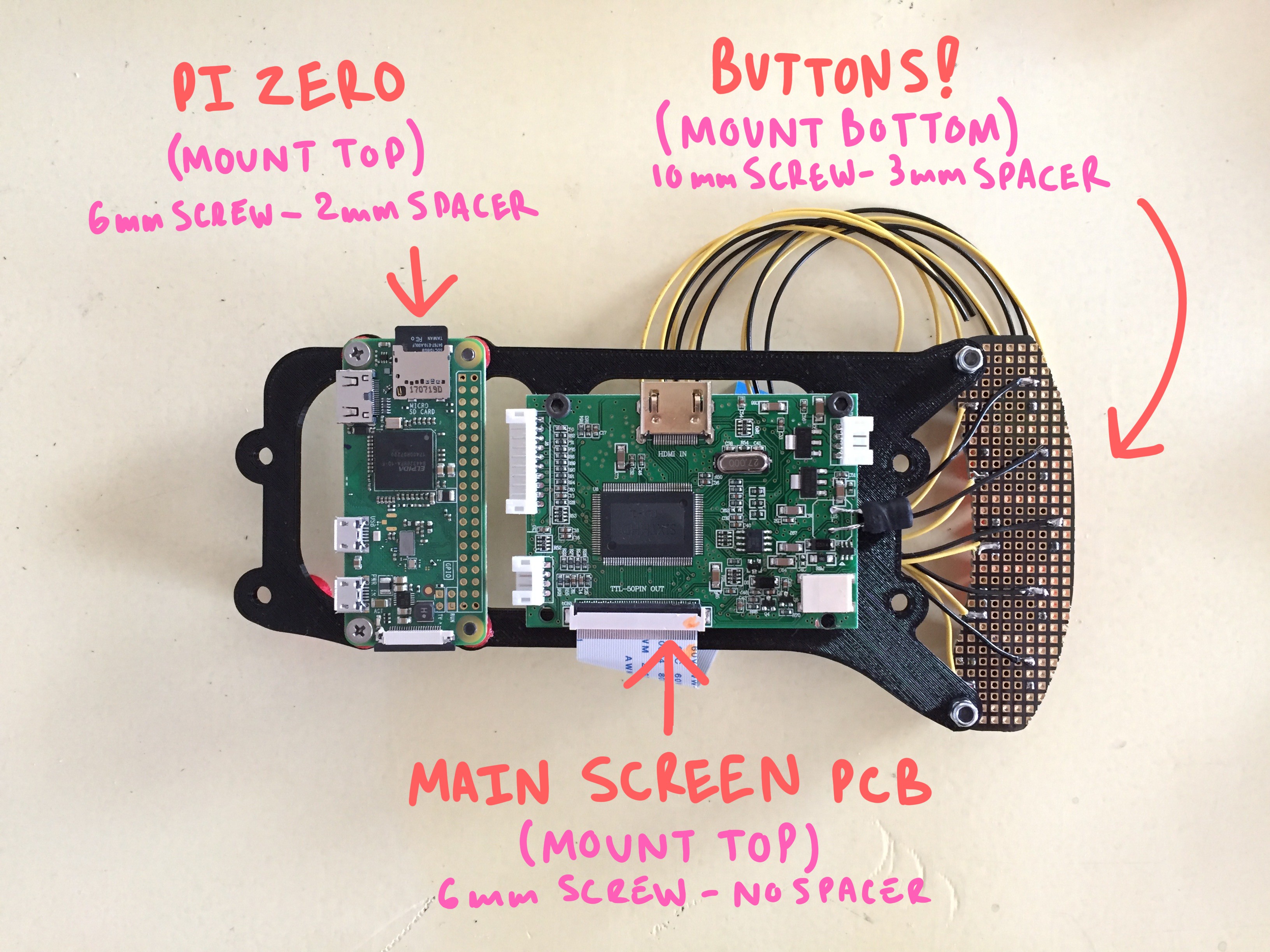
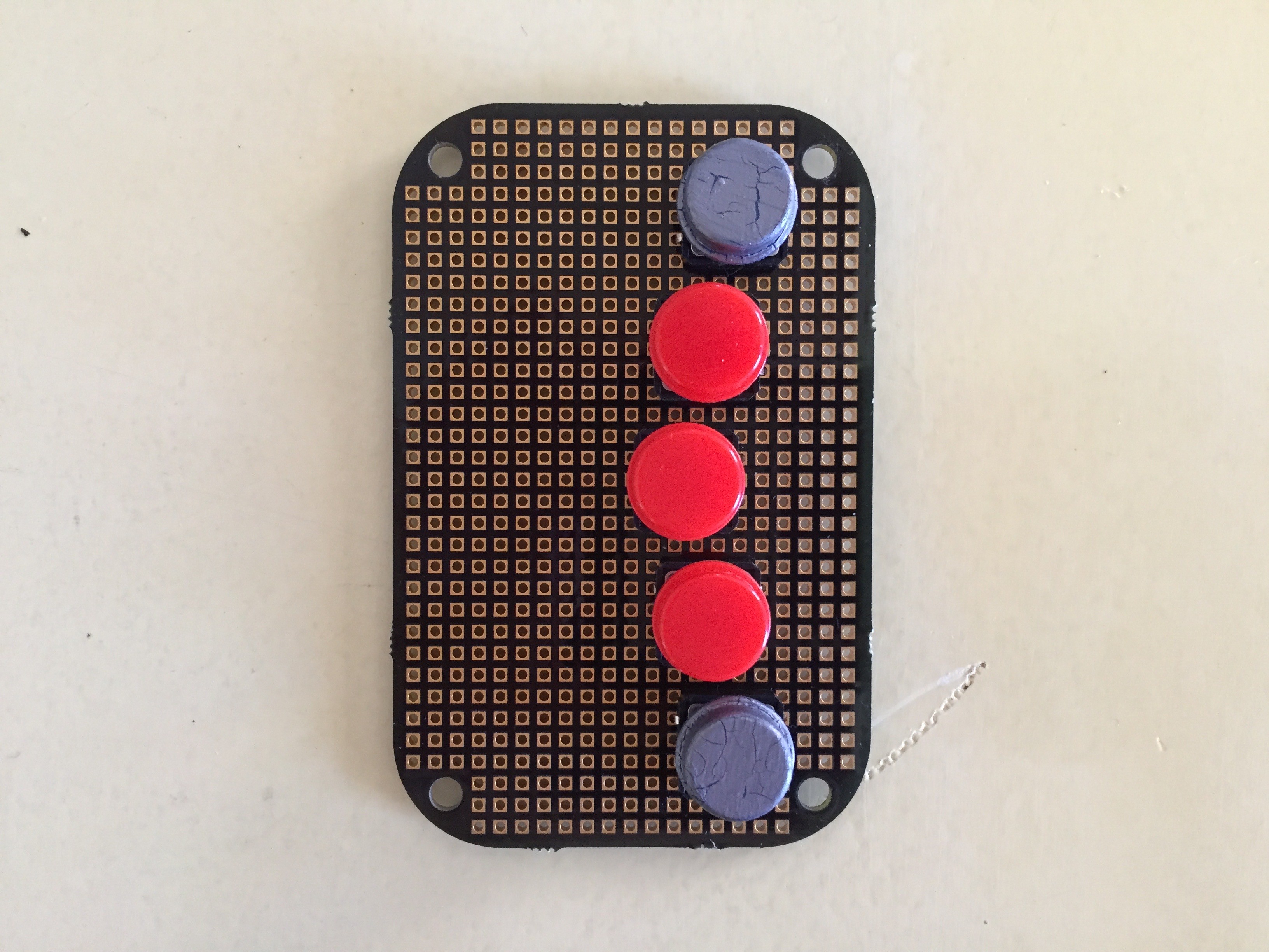
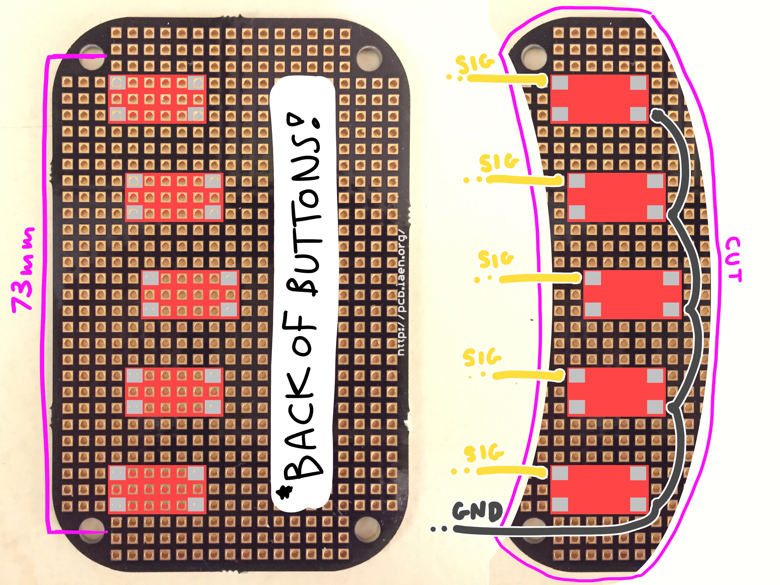
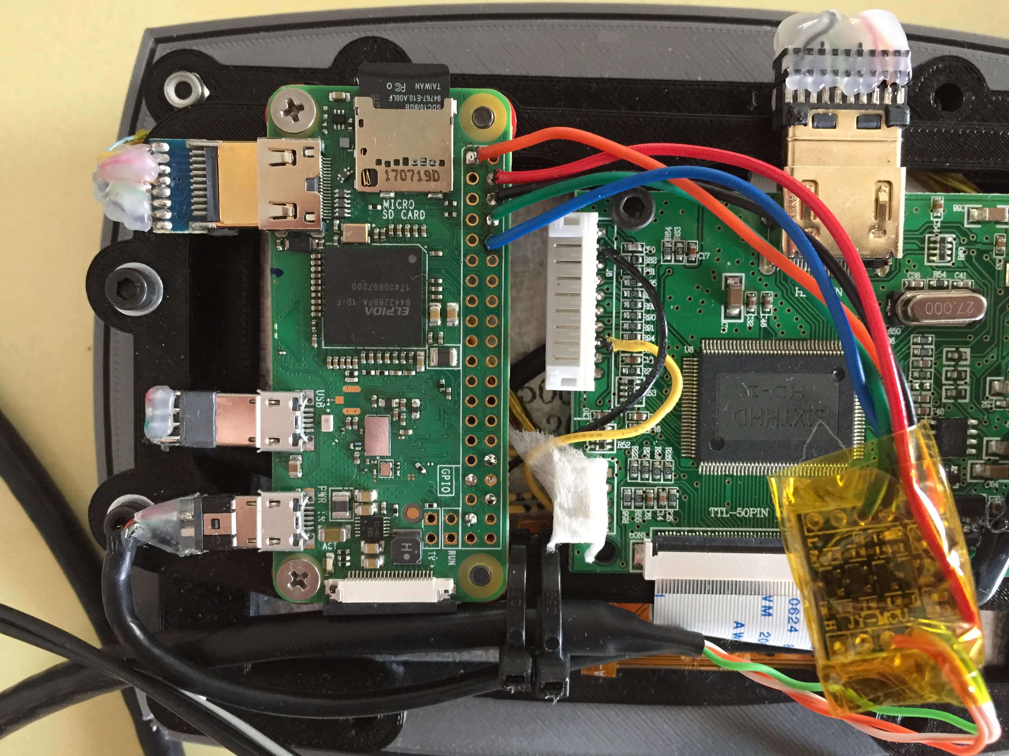
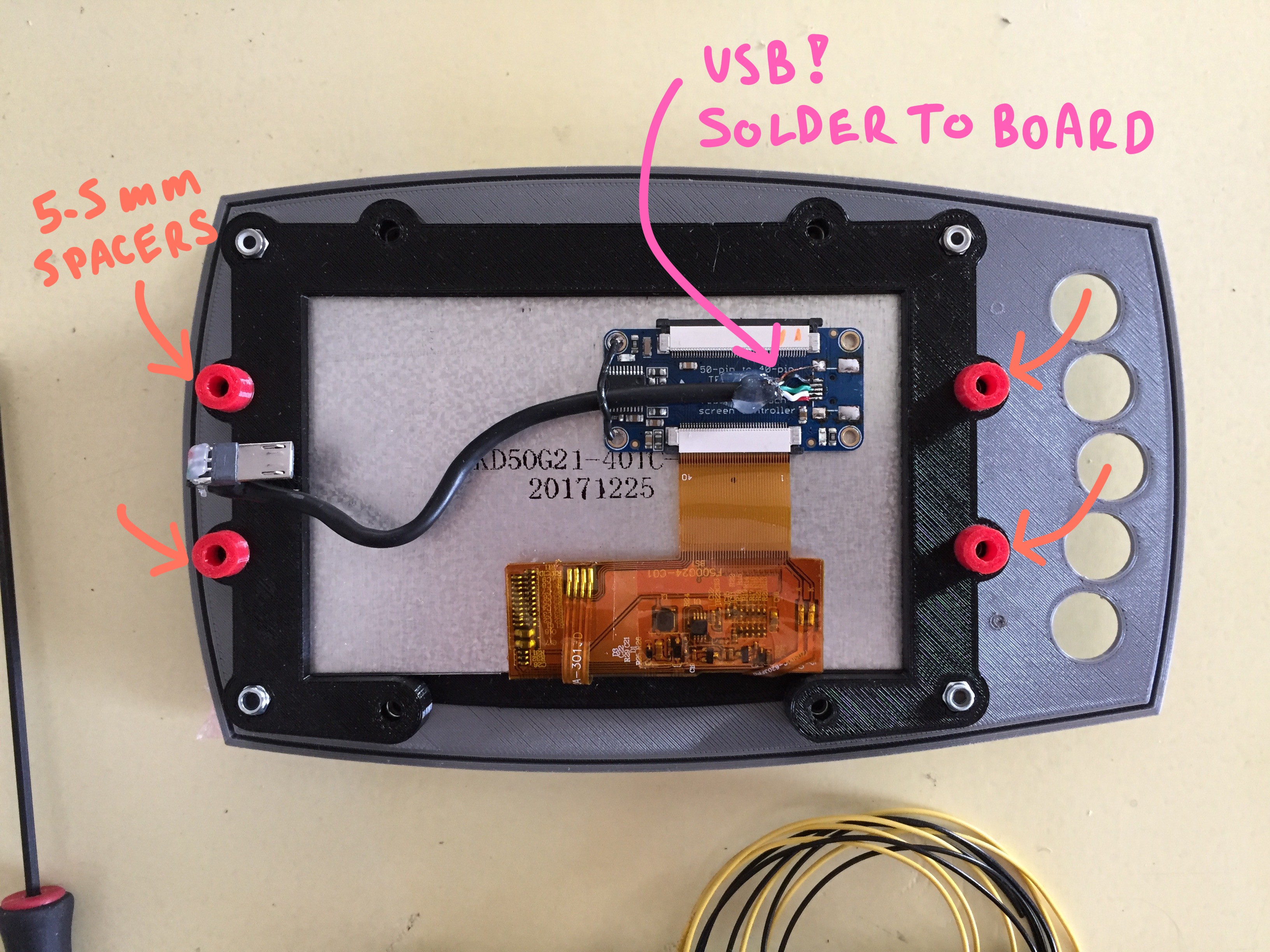
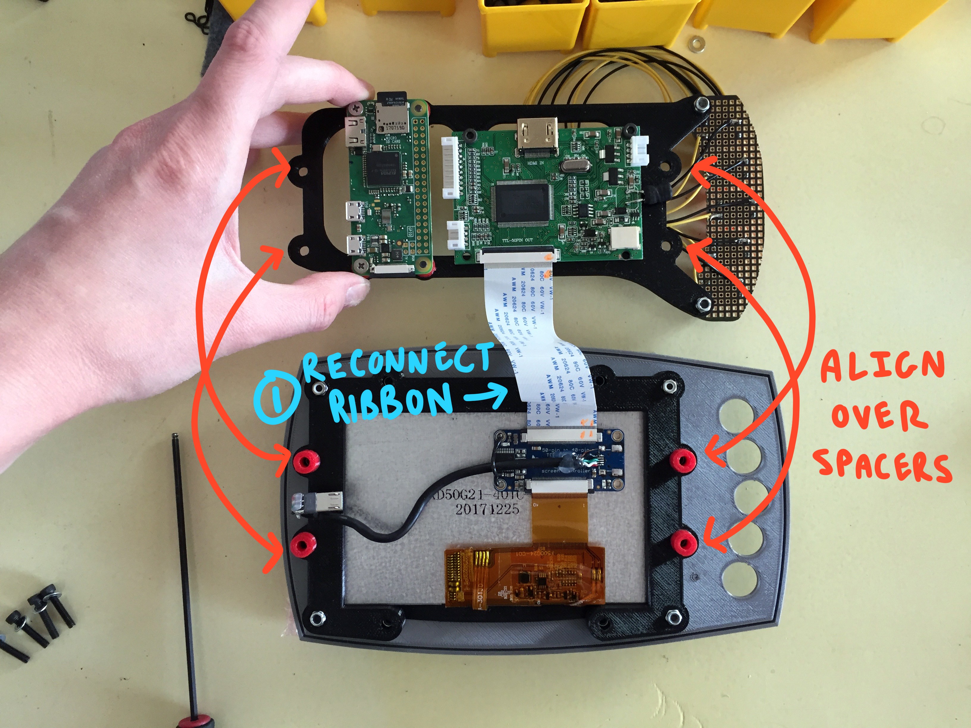
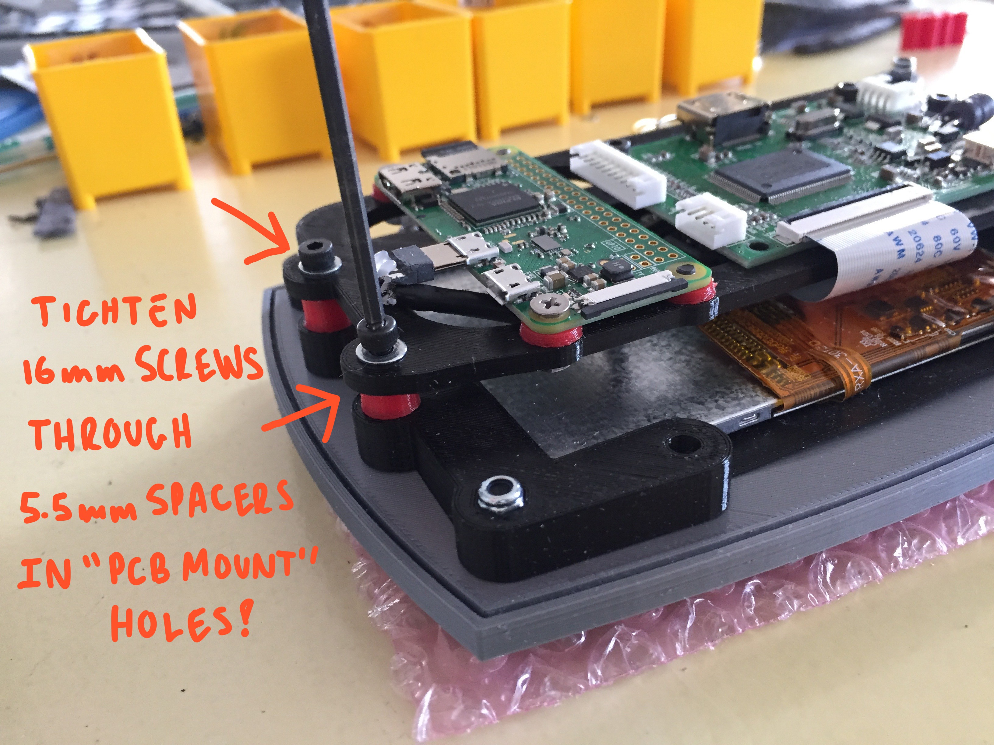
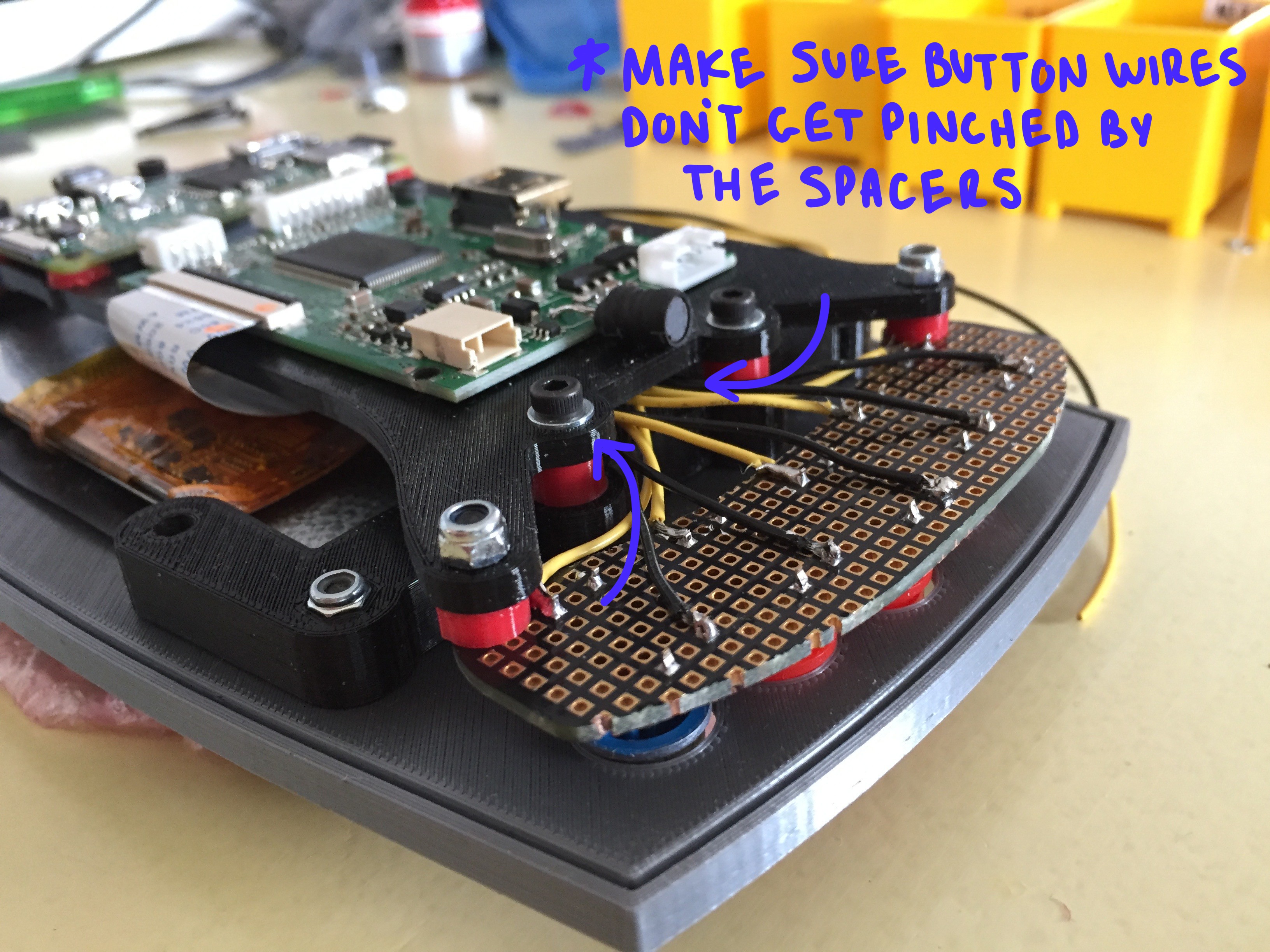
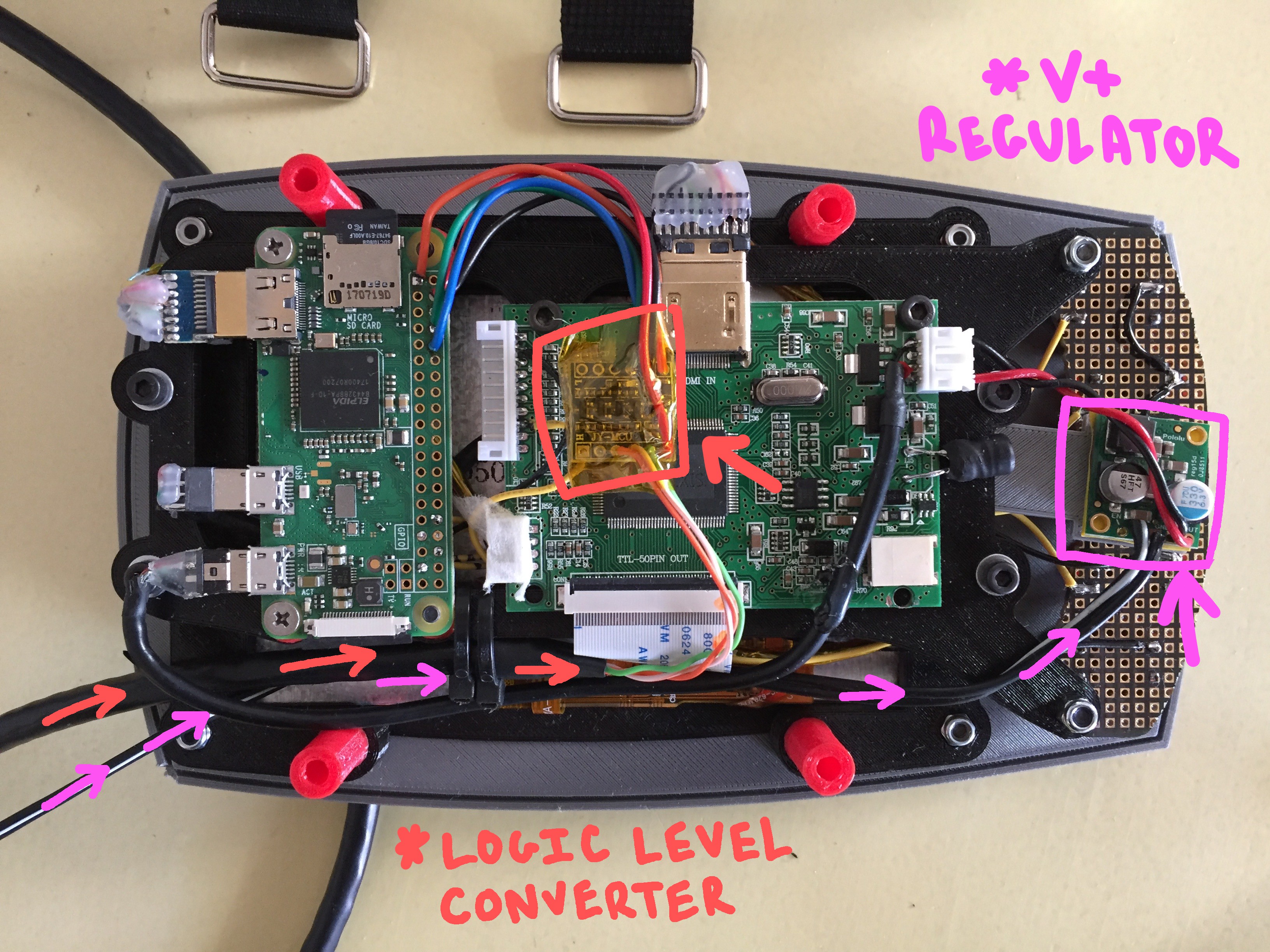
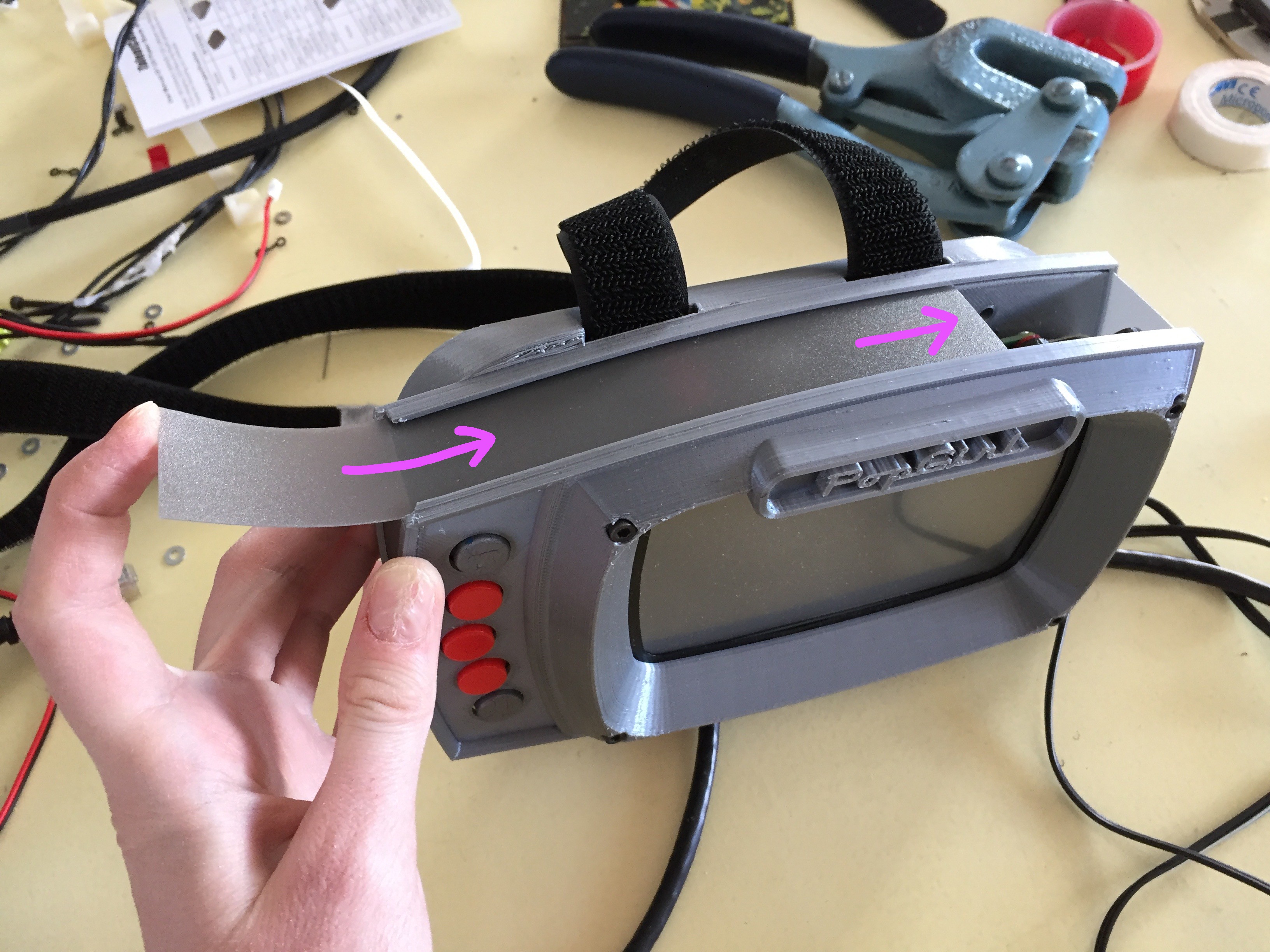
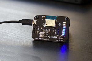
The scope of this project involves the creation of many individual systems, all with their own poetry and quirks. So far I have finished one peripheral, the "BEAT BOX" - however, several others are in the works right now for other parts of the body...

topFrame.stl

for PULSE PACK enclosure

Standard Tesselated Geometry - 367.56 kB - 10/21/2018 at 23:40

Download

Harness_Adaptor.stl

for PULSE PACK enclosure

Standard Tesselated Geometry - 104.77 kB - 10/21/2018 at 23:39

Download

bottomFrame_inside.stl

for PULSE PACK enclosure

Standard Tesselated Geometry - 132.70 kB - 10/21/2018 at 23:39

Download

Base_1.stl

for PULSE PACK enclosure

Standard Tesselated Geometry - 277.04 kB - 10/21/2018 at 23:38

Download

harnessMounts.stl

for PULSE PACK enclosure

- 218.25 kB - 10/21/2018 at 22:59

Download

View all 29 files

  • Preparation for SuperCon!

    Sarah Petkus10/28/2018 at 01:09 0 comments

    My pilgrimage to Pasadena for superCon is now synonymous with the beginning of Fall. I start enjoying the crisp chill in the air at night, eat a lot of sweet candy, have a couple weeks where I'm busier than sense... and then, BAM! I'm in the car with a bountiful harvest of whatever nonsense I've been concocting to show to my friends and fellow hackers.

    It's my favorite *con* or *festival* or *gathering*- I enjoy being with my people, and seeing all the inspiring work that's been unfolding in the now.

    This hacker harvest fest (I'm going to call it that) is fun, but it also brings a fair amount of stress in the week or so leading up to it. That's where I find myself right now.

    My intention is to bring the whole SHE BON project along with me to demo and share during the three days of festivities. I won't be wearing all the augments at once- but I will wear them all at some point throughout the con, so this means they all need to be *wearable* and mobile, - they must all have power supplied to them! somehow.

    My biggest hurdle this weekend is wrapping up some obvious (potentially critical) odds and ends. primarily, how my 3D printed assemblies will in fact mount to the fleshy surface of my body - amazingly, I didn't think this far for some items, like the salmon "panties". (this also comes with decisions about what I'm going to wear underneath them).

    THE BIG TODO

    • mount and manage PCBs and wire harness of winch belt
    • better belt buckle for winch belt
    • run power to winch belt from pulse pack
    • install core power supply to pulse pack + voltage regulator step down for sub systems
    • tighten up pulse pack cat5 ports >.<
    • arm brace for popgirl
    • instal voltage regulator for winch belt
    • make beatbox wearable!
    • tweak salmon code for heat monitor
    • power the salmon
    • fit the fillet-o board into the new salmon
    • rebuilt circuit for propeller pasties
    • make a bra attachment for pasties
    • also need to run power to pasties 

    Any how. The layout of the SHE BON main site has been updated again to reflect all the new additions to the suit. 

    Enjoy the concept art and stuff! I'll see you at superCon!! <3 

  • AS OF NOW

    Sarah Petkus10/22/2018 at 01:58 0 comments

    The Hackaday Prize Finals are nearly upon us. I've pushed a lot of information into the ether in the past few weeks, so I figured it wouldn't be a bad idea to post a summary of all that I've created up until now.

    As it stands- I have produced the first iteration of the core platform: the PULSE. This includes the core brain and user interface, which are open source, fully documented on this page, and ready for you to replicate or fork for your own devious schemes.

    THE SHEBON PLATFORM

    documented in detail for your use:

    THE PULSE (PRIMARY BRAIN)

    THE POP GIRL (USER INTERFACE)

    THE WEARABLE AUGMENTS

    created for my personal use, but I hope they inspire

    I've built a device to satisfy five of the nine augments I proposed creating for this series of wearables (YAY!)

    • The Propellor Pasties
    • The Beat Box
    • The Hot Spot
    • The Spank Skirt (in the works)
    Read more »

  • The PULSE PCB

    Sarah Petkus10/21/2018 at 20:59 3 comments

    This board is the heart of the SHE BON project. It's nothing horrifically fancy - however I've designed it to serve the specific functions of the project.

    It is equipped with an ATMega 1280 (like the Arduino MEGA)- and is broken out to 9 molex connectors along its edge, which are meant to serve power and data to multiple subsystems.

    It has been designed to mount inside of something- and in this case for the SHE BON project- I've mounted it inside of a backpack wearable, with the MOLEX connectors terminating at the backpack's edges at RJ45 connectors.

    ASSEMBLING YOUR OWN PULSE BOARD

    If you'd like to save yourself some trouble, you can buy this board directly from me on Tindie. However, the layout is open source, so if you feel so inclined, you may have your own fabricated.

    The bill of materials can be found on my SHE BON gitHub, as well on the project page here on hackaday.io

    THE NEXT REVISION OF THE PULSE

    I mentioned above that this board serves much the same use as an Arduino MEGA (its io pins are just distributed all fancy like). 

    While this board will get you started, whether you're a beginner or vetted hacker, there are some improvements I'm making to the next iteration of the PULSE that will give it some vital functionality for the scope of the project.

    Rev. 2 of the PULSE will include:

    • an SD card reader for logging data
    • a small eINK display for status indication
    • possibly different connectors along the edge

    If you personally have an suggestions on how I could improve this board for its intended use, please let me know! I'm admittedly more of a mechanical person than an electronics buff, so it's likely I don't know what possible! :)

  • POPgirl: Raspberry Pi Setup Steps

    maehem10/21/2018 at 05:58 0 comments

    PopGirl Hardware and Software

    Much of this is typed from memory and may be missing a step or some other detail here or there.  Please feel free to share any corrections or contact us to help you get through a step that is failing.

    In a nutshell:

     -  Set up a RaspberryPi Zero W with a fresh Raspian. 

     - Enable SSH and VNC.

     - Disable the serial console.

     - Increase the GPU RAM allocation to 128MB.

     -  Remove the Oracle Java and install OpenJava and OpenJavaFX. 

     - Install Pi4J

     - Install WiringPi to version 1.2 or newer.

     - Test our JavaFX based app.

     - Automate the app startup at boot time.

    HARDWARE

    The PopGirl uses a Raspberry Pi Zero W to drive a AdaFruit 5" LCD with touch panel.  The serial port pins (RX and TX) on the GPIO connector are level translated to 5V signal levels for communication with the heart shaped sensor processor board that is located in the heart-shaped backpack.

    The sensor board collects and formats sensor data and then bursts them over the serial line once every half-second.  The Raspberry Pi listens for this packet and decodes the values into their respective display values.

    RASPBERRY PI ZERO

    Configure a microSD card to run "Raspian with Desktop" from:

    https://www.raspberrypi.org/downloads/raspbian/

    If you are new to Raspberry Pi, there are a number of utilities to burn the Raspian image to the SD card.   On our Mac, we used: Apple Pi Baker https://www.tweaking4all.com/?s=apple+pi

    At first, you should hook your Raspberry Pi up to a regular monitor, keyboard and mouse.  Boot the system up.

    You will want to ultimately enable SSH and VNC so that you can administer and test the app from the comfort of your PC or Mac.  Here is a link for how to enable SSH and VNC.  Any other services should be left alone at this point as we don't use them.

    https://www.raspberrypi.org/documentation/remote-access/

    Disable Serial Console (because we need to use it for our hardware).

    Read this to understand how to configure the serial: https://www.raspberrypi.org/documentation/configuration/uart.md

    See the section called "Disabling Linux's use of console UART"

    SOFTWARE

    The PopGirl app is written in JavaFX using OpenJava8 but also leverages Pi4J and WiringPi to allow serial port communication as well as GPIO functions.  There are a number of steps to get the stock Raspberry Pi ready for running the Java application.

    The Oracle Java8 that is included with the Raspbian distribution will not work for JavaFX.  Oracle has decided to decouple JavaFX from the core Java going forward.   Future versions of Java will have a better mechanism for add JavaFX as an optional module, but for now we need to uninstall the Oracle Java and replace it with OpenJava.  Then we can add the OpenJFX library.

    Remove Oracle Java:

    sudo apt-get remove --purge oracle-java8-jdk

    Add Open Java:

    sudo apt-get install openjava openjfx

    WiringPi (to access the GPIO/Serial pins from Java)

    The version of wiring-pi should be 1.2 or above.  If it's 1.1 then you need to replace it:

    curl -s get.pi4j.com | sudo bash

    This Pi4J reference may also help:    http://pi4j.com/install.html

    GPU Memory Setting:

    From the Desktop go to: [Menu] --> [Preferences] --> [Raspberry pi config..] --> [Performance]

    Adjust the GPU memory to 128

    APPLICATION

    At this point, JavaFX applications should run OK.

    Hiding the mouse cursor

    Since we are using a touch screen, we want the mouse cursor to disappear.  There's an app for that:

    https://spellfoundry.com/2016/05/29/configuring-gpio-serial-port-raspbian-jessie-including-pi-3/...

    Read more »

  • POPgirl : Hardware & Enclosure Build

    Sarah Petkus10/11/2018 at 05:06 0 comments


    I made a status indicator that notifies me of my body's relative state of arousal!

    To help me visualize what's going on with the myriad of wearables I have set out to don at once, I've created an arm-mounted screen display that will tell me what I need to know at a glance.

    The development of this little treat was of course a matter of hardware design and software development, so I'm breaking the build log into two parts. This first edition will cover the physical components, like the electronics, the enclosure for the electronics, and any other bells and whistles I needed to create to make it do.

    BILL OF MATERIALS

    Electronics stuff:

    HARDWARE SIZES:

    OTHER THINGS YOU'LL NEED:

    • soldering iron
    • access to a 3D printer
    • filament in cool colors
    • metric screw driver
    • pliers 
    • sleet plastic (up to 1/16 inch thick)
    • patience*

    *I say you'll need patience, but really... you will need to perform some light modification of some cables in order to get them to fit within the profile of the enclosure. Specifically, you'll need to strip some of the casing from a USB mini cable, as well as strip the plug casing from an HDMI cable. =O

    We'll talk more about that later.

    THE PRINTED STUFF

    You'll be glad to know that there are only 5 core pieces you'll need to print in order to make your own POPgirl enclosure. 

    The .stl files can be found on my SHE BON gitHub repo!

    The bad news is that a couple of them will take close to six hours to print a piece.

    Stylistically, I chose to print the enclosure in silver and black... but you can use whatever colors of filament you'd like, of course. Here are the two trays of parts according to the color they'll be represented as in these build instructions:

    SILVER PARTS:

    • face_plate (~7 hours)
    • arm_mount (~8 hours)

    BLACK PARTS:

    • PCB_mount (~1 hour)
    • screen_frame (~2 hours)
    • screen_gasket (5 minutes)

    SPACERS:

    In addition to the primary pieces, there are some super important spacers you'll need to print. I chose to print them in red, so they're easy to spot in case they roll off the table into the forever carpet.

    The other important thing to note at this point of the build, is the length of hardware that goes with each space. This is key, because the screw length must be such that it is long enough to reach the countersunk nut it is being screwed into, but not too long otherwise it will bottom out (or poke a hole through the enclosure)

    • (4) 5.5mm 
    • (4) 17mm
    • (2) 2mm
    • (2) 3mm

    CAPTURING THE SCREEN

    This entire build is constructed around a 5" touchscreen monitor which you can pick up from AdaFruit for ~$80. It's a little awkward to use, as it comes with three horrible PCB tumors hanging off from it at odd angles... but if you take care to secure them in place when you get it, they aren't the worst to work around.

    Right away you can disconnect the ribbon between the screen itself and the main PCB, and also unplug the button...

    Read more »

  • The Meat and Potatoes of SHE BON

    Sarah Petkus10/04/2018 at 17:05 0 comments

    I'm creating a series of wearable tech for use throughout my body, which will sense and indicate different aspects of my physical status!  While my personal reason for developing this technology is intimate in nature, the system I'm creating could easily serve a number of purposes in other contexts as well.

    • if you have ever wanted to create a wearable device that senses information from your body
    • wish to create a wearable that expresses something about your immediate state
    • have a need to network multiple unique wearable projects together
    • would like to visualize data received from sensors imbedded in devices you've made

    ...then SHE BON might help!

    I'm going through lengths to document my progress on the development of this platform, so that it can serve someone else as just that: a platform from which you can build upon for a countless number or reasons.

    Read more »

  • Hip Winches

    Sarah Petkus09/25/2018 at 22:23 1 comment

    My goal this past week was to create a belt of hip-mounted winches! 

    Why, you ask? In short, my next peripheral for SHE BON require I scheme up a mechanism that is able to create thigh gap between my legs by pulling apart the meat of my buns. You can read more about this on my introductory post about the HOT SPOT.

    For this cause, I decided to use a pulley/tendon system, which yanks at a long strip of kevlar rope adhered at a diagonal bias across the plane of my flesh just below my buns.

    1. To do this, I first had to calculate how strong my motors would need to be in order to supply enough torque for the job. 
    2. Second, I'd have to mount these said motors at the right angle on my fleshy body, however solidly enough so that they stay put relative to the pieces being tugged.

    The later is as challenging as it sounds. I'm running into much the same issues as with my propellor pasties: the human body is a terrible anchor point for mechanical components... *sigh*

    Read more »

  • Goals For the Next 30 Days!

    Sarah Petkus09/22/2018 at 00:47 0 comments

    FIRST OF ALL, SHE BON in a finalist in the Human Computer Interface category for the HackaDay Prize!! This is so very exciting!! =D

    This means two things: ( 1 ) I get a little bit of money as a result to spend on materials and parts ( 2 ) I have a TON of work to do in the next month!

    As a refresh on the memory, the SHEBON project will involve the creation of (9) unique wearable augments! Even though I intend to complete them all in time, I can only expect to make so much before the HackaDay Prize judgement period begins on October 22nd.

    It seems like a good time to hash out my goals before then, and also go over what I am preparing for open source documentation!

    As much as I'd like to have the entire project ready to prance in by the middle of next month, I don't have enough humanly power and waking hours to pull that off. I will try my hardest to have a decent sampling to show... say... a full outfit. Here is a list of the sub-systems I will shoot have have developed by the judgement period:

    1. nips (propellor pasties) 
    2. pelvis (beat box)
    3. buns (spank skirt)
    4. thighs (hot spot)
    Read more »

  • Away for August! (but not lost!)

    Sarah Petkus08/31/2018 at 00:36 0 comments

    Hey everyone! I realize I teased with two new enticing project challenges: the "HOT SPOT" and the "SPANK SKIRT" and then went quiet all month long!

    The reason is that I have a very important exhibition coming up at the beginning of September involving my robot offspring, NoodleFeet, and needed to focus all of my parental energy into readying them for the big day!

    I promise to get back to SHE BON soon. I have an update on the HOT SPOT in progress right now, and am well on my way to getting both peripherals up and working (to some relative degree for a first iteration lol).

    Until I return, you can check out what I've been preparing for on my youtube channel : ROBOHEMIAN! (I'll be in Linz for the ARS Electronica festival)!

    Here is a little bit of the fun I had a few weeks ago while calculating how much torque is necessary to spread my buns. :3

  • Talking About SHE BON @ HDDG 32

    Sarah Petkus07/29/2018 at 22:02 0 comments

    Two weeks ago I gave a talk about SHE BON at one of Supply Frame's HDDG Meetups in San Francisco!

    This was super exciting for me, as it was the first time I spoke publicly about the project. I really had no idea how it would go over with humans outside my immediate social bubble- and I was pleased with the amount of feedback I received from everyone at the bar afterwards.

    Read more »

View all 17 project logs

  • 1
    PULSE PACK Enclosure Build

    The PULSE PACK is a wearable computing platform that orchestrates a collection of body augments, all part of the SHE BON project. These augments are individual systems that sense and indicate when the user's body enters an "excited" state. Each system is designed for a particular region of the human body and uses various types of sensors to detect bio-data as input, and then communicate the user's status with electronic and mechanical devices as output.

    You can think of the PULSE PACK as a wearable breakout board. Its primary function is to house the master circuit board, called the "Pulse". This heart-shaped Pulse board sends power and data over a network of cables, much like a heart pumping blood to distant organs through a series of veins.

    Why would I have the platform which senses and triggers the indication of my arousal be a BIG. TRANSPARENT. PULSING. HEART-DRUM?......Well... it might be a metaphor. ;)

    I am defining the cyber-punk reality I wish I lived in by creating my own works of technology and art. Also, there is something satisfying about a wearable that routs wires all over my fleshy bits. Bottom line, this is another meditation in the book of Sarah: body data as a means to communicate the intimate and the unseen.

    ---------- more ----------

    In this build log I will outline how I crafted a transparent *stitch free* backpack, from vinyl and a 3D printed frame which I designed in Fusion360. This log focuses primarily on the enclosure. I will publish more about the circuit board and how the system works in a separate post!

    ( This post will outline the build of the *yellow* heart... since I was bad and forgot to take pictures while assembling the *red* one... <3 )

    THE VINYL

    So, all it takes to create a heart backpack is (3) pieces of vinyl. (2) identical heart shapes for the top and bottom vinyl, and (1) longer strip that will act as the outer wall and body vinyl:

    notice: The outer wall piece has some holes in it! These are where the "bulkhead" adaptors mount along the edge of the backpack!

    These vinyl pieces mount to the 3D printed frame with plastic rivets which thread through a series of small corresponding holes on the plastic and vinyl. I printed a paper template from a dxf I exported straight from fusion360 to ensure everything was precise:

    I used a punch to poke the tiny 2.4mm "rivet holes" and the 4mm "hardware holes" around the edges of each piece:

    THE MOUNTING PLATE

    This is technically still part of the primary backpack body, but its function has more to do with coupling to the PCB mounted in the center and the harness that's worn by the user. So basically the function of these three parts are as follows:

    • back plate: couples to the harness
    • adaptor plate: couples to the backpack
    • front plate: couples to the PCB

    ...but Sarah... why does there have to be three separate pieces? Would it be easier if they were design as just one?

    -Since all of these pieces bolt onto their respective assemblies with 3mm hardware, layering them this way facilitates in capturing countersunk nuts in between:

    back...

    The extra top and bottom piece help to capture all of this vital hardware in place and prevent it from falling out when I wish to bolt onto the mounting plate later on

    This happily joined (3) piece assembly can be directly mounted onto from the back and the front!

    THE PRIMARY ENCLOSURE

    As mentioned, the primary enclosure is "stitch free". I designed it this way because I didn't want to attempt hand sewing vinyl fabric at 90 degree angles in less-than-straight lines. To connect the seams of my vinyl pieces, I plastic welded my vinyl to the a 3D printed frame with small rivets made from raw 3D printer filament.

    Don't get me wrong, this method likely wasn't any less tedious than hand sewing with a punch and thread... BUT, it felt like I had more control during the assembly process. Once everything was in one piece, the hard frame structure helped define the backpack's overall shape.

    The vinyl attaches to the pieces of the frame with tiny plastic rivets to complete (3) separate parts: the top heart,the bottom heart, and the body.

    Four pieces total make up the body frame:

    • (1) body_front_left
    • (1) body_front_right
    • (1) body_back_left
    • (1) body_back_right

    The parts for the body are kinda fancy because they have a channel sticking up at a 90 degree angle which is meant to receive the long strip of vinyl used for the outer wall of the backpack:

    There are similarly (4) smaller pieces for the top and bottom frame, making for (8) pieces total:

    • (4) topBottom_left
    • (4) topBottom_right

    The body vinylgoes with the body framepieces, and the top and bottom vinylpieces mount to the top and bottom framepieces:

    PLASTIC RIVETS + HARDWARE

    The plastic riveting technique is simple. I cut many 7-10mm pieces of raw 3D printer filament, and threaded them through the corresponding holes of the vinyl and frame, melting a cap on each end to hold it in place. (this is more or less sewing but with plastic).

    To prepare the rivets, I cut pieces until I was numb inside:

    ...I then used my soldering iron on low heat (~280 F) to melt a cap on one end:

    I decided to weld the top and bottom pieces of the enclosure together first (since they're a bit easier to do). There are (6) pieces total for each the top and the bottom. They make up two halves of two frames which sandwich the vinyl in between them like two slices of bread. Two smaller joint pieces connect the halves in the middle (because I couldn't fit each frame as a whole on the printer bed!)

    I used some 3mm hardware in the larger holes to temporarily hold everything in place while I placed my rivets:

    The holes in the frame lined up with the holes in the vinyl! success!:

    The smaller holes are begging to be skewered by those rivets!:

    I pushed two or three in at a time, and then used my soldering iron to melt and flatten out the opposite end. It's important to keep the cap semi-flush with the frame as to keep everything pressed together tightly.

    The steps are the same for both the top and bottom parts of the enclosure.

    Lastly, I had to repeat a similar process with the body of the heart enclosure! This involves the meatier frame pieces and the remaining long strip of vinyl with the large holes along the center:

    This is slightly trickier than the alignment of the top and bottom, because the long "side wall" piece of vinyl must seat in a long slot that sticks up off the frame at a 90 degree angle:

    The length of the vinyl begins in the top "pinch" of the heart shape, runs along the whole diameter of the backpack and then terminates in the same location on the opposite side:

    Similarly, there are a series of smaller holes along the frame that line up with the hole in the vinyl... and they want the same treatment:

    It's much easier to get a soldering iron to the rivets if they are threaded from the inside of the heart and poking out as seen below:

    Once all of those sharp spikes bits are capped off... I had to repeat the same song and dance with the top pieces. It's about as tricky to slot the upper lip of the vinyl into the channel of the frame, so I had to be patient!

    Once plastic welded together, the middle of my enclosure was complete (mostly). I now had two frames attached to the outer wall of the enclosure, like an accordion:

    Once the plastic welding of the top heart,the bottom heart, and the bodyis complete; the next step is to combine the three fully assembled parts into one. I designed some clamp-like bracketsto do the job!

    Before adding the structural brackets, I needed to insert the mounting plate! This is super important, as everything critical mounts to this one piece:

    Once guided inside, the mounting plate screws into the bottom frame pieces from the back...

    This is what the assembly looks like once the mounting plate is in its proper position:

    The brackets hold the three pieces of the enclosure together like clamps; sandwiching the topand bottomframepieces to the middle frame piece. The 3mm hardware screws into captured nuts located in the middle frame pieces. In the image below, you can see the hardware going through the bracket, then the bottom framepiece, with a small bit of length left to screw into the middle framepiece of the enclosure:

    the top portion of the middle framepiece attaches to the front half of the bracket:

    ...and the hardware also screws in from the back, so that the meat of the screw is sticking up. I capture the top half of the middle frame in place by adding a nut above the bracket:

    The top frame piece drops onto the remaining thread of the hardware now poking up from the brackets! FIRST however, before I close this thing up, I want to install the portals along the wall of the enclosure!

    These sad empty holes need to be filled with something! A silver porthole adaptor threads through these gaps and houses a special PCB which converts wires for a molex connector into a cat 5 terminal.

    So many holes:

    While I print (9) of these "bulkhead" adaptors, I'll dress up my brackets a little :P I picked up some adhesive reflectors from Home Depot!

    I cut the red and white shinies into small strips to place on every-other bracket:

    Around the time I was done with this task, the port-hole pieces and their corresponding nuts were finished printing and ready to go into the outer wall of the enclosure:

    THE STRAPS

    It was my goal that the straps of the backpack form to the contours of my shoulders. This wasn't hard to do, but I did need Mark's help placing short segments of masking tape directly on my skin to sculpt out the first rough pattern (in blue). The first two versions on the left were blind attempts where I just guessed at the curve needed to pull this off... and both were very much unsuccessful. The two on the right were the result of adhering tape directly to my body. You can see how off my first attempts were: =P

    I chose to use an old roll of shelf liner material for my straps. This particular beige-colored fabric was slightly thick and had a spongy quality which I thought would be comfortable to wear. Most importantly, it doesn't deform when stretched or pulled, even with significant force:

    I used my handy template to cut my straps in the beige material, as well as in vinyl. Since I wanted the vinyl to wrap around the edges of the shelf liner, I added a quarter inch margin past the template.

    In order to fold the margin around the edge of the shelf liner, I had to cut out small wedges at the apex of each major curve (if you aren't sure where to cut them, just do so every inch or so on average!):

    Next I folded the tabs down and taped them in place using some micro-pore paper tape. This shit is awesome because its incredibly thin, but sticks very well to pretty much everything! Since its soft, thin, and fabric-like, I am able to leave it  permanently inside my straps instead of worrying about finding a way to remove it later:

    To make the straps of the backpack a bit more comfortable to wear on my shoulders and chest (and to cover up this unsightly abomination of secret tape), I added neon yellow fleece to the back side:

    I even got some matching neon yellow thread to stitch the seams together with:

    A short loop of elastic at each end will allow the harness to give slightly while I'm trying to get the backpack on, and will also help me mount them to the adaptor plate seen below:

    THE HARNESS ADAPTOR

    Theharness adaptor screws directly onto the mounting plate within the main enclosure. It is also the thing that the harness attaches to directly:

    I skinned the adaptor plate in the same fashion as the harness; with vinyl on the front, and fleece on the side which makes contact with my body:

    fleece do:

    Basically, the harness and the adaptor are their own separate assembly

    COUPLING THE HARNESS TO THE ENCLOSURE

    The harness adaptoris mounted to the back of the main enclosure, directly onto themounting plate:

    The hardware used to make the connection screws into the nuts that are captured on the other side of these holes pictured below:

    Once bolted down, this is what the back of the heart enclosure looks like:

    Flip it around to view the whole assembly from the front, and you're now looking at this:

    Here is the shiny new yellow next to the seasoned red backpack:

    so pretty!

    THE PULSE PCB

    The circuitboard running the show is called the PULSE, and for the time being... it is more or less a repackaged Arduino MEGA. As mentioned, there will be (is) a separate post all about it. For this build, all you need to know is that this heart-shaped thing mounts in the center of the backpack on some standoffs =P

     the red PCB looks pretty sharp mounted in the new yellow enclosure, me thinks:

    MOLEX TO CAT 5

    I think first and foremost, the concept evolved around the aesthetic of having large chunky cords stemming form a central location at the core of the body, and feeding out to other locations, like veins.

    In some miscellaneous daydream of mine early this year, I imagined this being something transparent and heart-shaped. Once my mind saw it, that was what it had to be.

    From the PCB mounted inside the enclosure, I saw many delicate wires terminating at the edge of the fabric, grouping together into bundles and then feeding out in all directions. I knew early on that I didn't want wires stretching all the way to parts of my body directly off the main board. That'd be silly, right?

    The initial solution was to use a common connector, like molex, to come off the primary circuitboard. It would then terminate at the edge of the backpack and switch to something else at this junction. The "what" is still largely undecided, but for this first iteration of the backpack I went with CAT5. Its what I have an abundance of in the lab.

    I designed a tiny little PCB that has the six wires from my molex connector going in one side, and a cat5 connector on the other side:

    Once everything is soldered onto these little guys, they slide into those silver bulkhead adaptors like so:

    Here is a closeup of the wires terminating into the BULKHEAD:

    ...and becoming a CAT5 socket on the other side of the outer wall of the backpack:

    Once rigged up, the nervous system looks something like black spaghetti:

    USB POWER

    For now, v. 1 of the PULSE board receives its power from a rechargeable USB brick. There are (14) LEDs on the back side of the PULSE, so in the case that nothing is jacked into any of the sockets, it can at the very least pulse with colored light and look pretty:

    NOW WHAT...

    I now have two core systems: one in red and one in yellow! I can wear whichever hue suites my current mood. That's the beauty of it. <3

    If any of this inspires you to develop your own platform; if not to sense arousal per-se, but maybe something else about your physical status that you'd like to communicate out in the wild- I hope you choose to create it!

    In closing: the point of this whole project is to get people talking about how we can use the technology we create to communicate better with one another (through new forms of self expression). This project focuses on intimacy, but really... a dialogue about anything matters just the same to me. =)

    Keep creating the things you wish to see exist, AND be the person who makes the experience of living more interesting for everyone. <3

  • 2
    POPgirl Enclosure Build


    I made a status indicator that notifies me of my body's relative state of arousal!

    To help me visualize what's going on with the myriad of wearables I have set out to don at once, I've created an arm-mounted screen display that will tell me what I need to know at a glance.

    The development of this little treat was of course a matter of hardware design and software development, so I'm breaking the build log into two parts. This first edition will cover the physical components, like the electronics, the enclosure for the electronics, and any other bells and whistles I needed to create to make it do.

    BILL OF MATERIALS

    Electronics stuff:

    HARDWARE SIZES:

    OTHER THINGS YOU'LL NEED:

    • soldering iron
    • access to a 3D printer
    • filament in cool colors
    • metric screw driver
    • pliers 
    • sleet plastic (up to 1/16 inch thick)
    • patience*

    *I say you'll need patience, but really... you will need to perform some light modification of some cables in order to get them to fit within the profile of the enclosure. Specifically, you'll need to strip some of the casing from a USB mini cable, as well as strip the plug casing from an HDMI cable. =O

    We'll talk more about that later.

    THE PRINTED STUFF

    You'll be glad to know that there are only 5 core pieces you'll need to print in order to make your own POPgirl enclosure. 

    The .stl files can be found on my SHE BON gitHub repo!

    The bad news is that a couple of them will take close to six hours to print a piece.

    Stylistically, I chose to print the enclosure in silver and black... but you can use whatever colors of filament you'd like, of course. Here are the two trays of parts according to the color they'll be represented as in these build instructions:

    SILVER PARTS:

    • face_plate (~7 hours)
    • arm_mount (~8 hours)

    BLACK PARTS:

    • PCB_mount (~1 hour)
    • screen_frame (~2 hours)
    • screen_gasket (5 minutes)

    SPACERS:

    In addition to the primary pieces, there are some super important spacers you'll need to print. I chose to print them in red, so they're easy to spot in case they roll off the table into the forever carpet.

    The other important thing to note at this point of the build, is the length of hardware that goes with each space. This is key, because the screw length must be such that it is long enough to reach the countersunk nut it is being screwed into, but not too long otherwise it will bottom out (or poke a hole through the enclosure)

    • (4) 5.5mm 
    • (4) 17mm
    • (2) 2mm
    • (2) 3mm

    CAPTURING THE SCREEN

    This entire build is constructed around a 5" touchscreen monitor which you can pick up from AdaFruit for ~$80. It's a little awkward to use, as it comes with three horrible PCB tumors hanging off from it at odd angles... but if you take care to secure them in place when you get it, they aren't the worst to work around.

    Right away you can disconnect the ribbon between the screen itself and the main PCB, and also unplug the button board all together, as we won't be using it.

    The other helpful thing to do as soon as you unpackaged your screen is to use some double sided silicone tape to adhere the thin and fragile touch-screen PCB directly to the back of the screen to keep it from flopping around all loose-like.

    Just tack it down where it wants to lay naturally, and you should be good.

    Take the "screen frame" and press-fit some nuts into all of the counter-sunk pockets. There should be (8) on the front, and (4) on the back.

    Then lay the back on the screen into the frame so that its front is unobstructed and flush with the printed plastic:

    next, place the thin gasket on top of the screen, lining up the four mounting holes at the corners. It should over-lap and frame the touch-area just slightly.

    Lastly, the big dance "faceplate" piece should mount directly on top of the gasket. Like up the same hole along the four corners.

    one these three pieces are sandwiched together, you can thread (4) 20mm screws through the from of the "Faceplate" into the corresponding counter-sunk nut holes in the "screen fame":

    The back should now look like this, with both the ribbon cable and the open edge of the "Screen frame" facing the bottom edge of the assembly:

    MOUNTING THE PCBS TO THE "PCB FRAME"

    There are three circuit boards that will all share a single mounting frame. On the far left, there should be your "Raspberry Pi Zero", in the center will mount the screen's "primary board", and on the right will mount a "custom button board" that you'll need to put together with some perf-board and those tiny push buttons I listed on the bill of materials.

    The completed board should look like this once completed:

    MAKING A CUSTOM BUTTON BOARD

    You will need to solder up a quick button board module specifically fit to the clearance holes in the face plate! 

    Don't worry! If you have standardly spaced perf board, then you're all set. The front of the board should look like this. Five buttons, staggered by one row in a slight bow to the left:

    Here is a diagram for the dimensions and space of the buttons as they should fit into the perf board:

    There should be a wire coming off from each button that is ~7" long... and at least on ground wire!

    One of your buttons should connect to the "INPUT" of the screen, so that just incase the screen doesn't boot up in the correct mode, you'll be able to easily change it without needed to hook up the whole button bar tumor which came with the screen. 

    Pick a button, and wire to the pad leading into these two pins of the "button board" connector on the screen's "primary board":

    The rest of the buttons on your "custom button board" can be wired into any input pin you'd like on the Raspberry Pi Zero. I personally chose these four pins on the pi:

    CONNECTING THE PCBs TOGETHER

    This part kinda sucks. :) 

    You will have to run *specifically* a 1' HDMI cable from the screen's "primary board" to the "Raspberry Pi" - but in order to get it to fit within the enclosure, you will have to skin it completely. (I will soon post a stream of Mark demonstrating how to do this)

    The fully skinned HDMI cable should be routed as such:

    There are eight remaining empty holes on the "screen frame" that will be used for attaching this PCB bracket, as well as for sealing up the enclosure.

    ATTACHING THE LOGIC LEVEL CONVERTER

    Floating inside of your enclosure, there will exist two voltage regulators. One is a logic converter which drops 5V to 3.3V, there other is for the system in general.

    The main voltage converter is available from Pololu.com, and will go between your power supply and the system at large:

    The logic converter is available on Amazon and will go between the Pulse board and the POPgirl's Raspberry Pi Zero board. The stripped end of your cat5 cable will attach to this board, as well as some wire going to your raspberry pi. The hookup will look like this:

    Once its connected, wrap the module in some capton tape and let it rest over the middle the screen's "primary board" like a little floaty tumor:

    ATTACHING THE VOLTAGE REGULATOR

    The next tiny glad that you'll need to prepare is the "voltage regulator". You can read more about it on Pololu's specs page!

    The cable from your chosen power supply should connect *in* to the board, and the male connector compatible with the screen's "primary pub" should be running *out* from the board:

    Place some electrical tape along the back of the board and wrap it in capton tape to protect it, as this module will more or less "float" inside of the enclosure like a rogue organ:

    The cable running *in* from your power supply should rout along the bottom edge of the enclosure next to the CAT5 data line.

    ATTACHING THE *FULLY LOADED* PCB MOUNT

    You'll be attaching your loaded PCB bracket to the four holes circled below:

    Grab your 5.5mm spacers and position them over these holes:

    Be sure to reattach your ribbon cable from the touch screen PCB to the main screen board before you position the "PCB bracket" above the spacers:

    Line up the holes of the "PCB bracket" over the 5.5mm spacers and the receiving holes on the "screen frame", and thread in your 16mm hardware. It will be received by the countersunk nut inside the "screen frame":

    Maker sure that while you are doing this, none of the wires coming off your custom button board are being pinched or twisted strangely:

    Make sure all of your cables are connected and that everything looks level and parallel. Then lay the assembly face down:

    Your "logic level converter" and your "voltage regulator" should seat roughly in the areas shown above. Be sure to wrap them in protective capton tape so nothing shorts out!

    ADD STRAPS TO THE "ARM MOUNT"

    Before you seal everything up, you'll need to do something a little screwy with your velcro straps (something I will likely fix in a later version of this build, but for now... we'll just do the weird work around)

    Slide your velcro straps through the flat channels in the "arm capture" piece that you printed. 

    You'll notice one of them has a hole overlapping one of the channels... OOOPS. You will need to pass a piece of hardware through there to seal of the enclosure, so we're going to have to punch some holes in the strap.

    Position the straps where they need to be fixed, relative to how they hit the girth of your arm, and then mark where the hole lands with silver sharpie:

    Once marked clearly... use a 4mm punch to piece the velcro strap:

    Yay! Now the hardware can pass through the strap when you're sealing up the enclosure!

    There are four remaining holes at this point =O position the 15mm spacers over these holes and use your 35mm hardware to seal the enclosure, screwing from the "arm capture" plate through the spacers, and into the corresponding holes on the "screen frame" (there should be countersunk nylock nuts ready to receive them!).

    CLOSE IT UP

    Align the holes of the "arm mount" piece over the remaining 17mm spacers and the remaining holes on the "screen frame":

    Make sure the cable from the power supply and the CAT5 data line are tucked along the inside of the spacers:

    You will use your 40mm to seal the enclosure. Make sure the top assemble and the "arm mount" sandwich the 17mm spacers and that none of your chords or wires are being pinched as your tighten down the screws into the captured nuts in the "screen frame".

    CREATE SOME EDGE

    Using some sheet plastic, cut small rectangles in the following dimensions:

    I found some semi-transparent grey sheet that defuses the inside slight from the indicator LEDs on the internal boards quite nicely.  Once cut, slide them through the channels along the outside edge of the "face_plate" and the "arm_mount":

    The right side of the enclosure wall should have a hole open for the CAT5 cable to pass through. 

    Once this finishing touch is added... you are ddddoooooonnnnneee.

    The final step is to get the software running on the Pi. So, maybe don't close the thing up just yet. =P 

    is glorious!

    The software instructions will come shortly! Until then- enjoy my wiggly concept sketch of the UI layout!

  • 3
    POPgirl Software Setup

    PopGirl Hardware and Software

    Much of this is typed from memory and may be missing a step or some other detail here or there.  Please feel free to share any corrections or contact us to help you get through a step that is failing.

    In a nutshell:

     -  Set up a RaspberryPi Zero W with a fresh Raspian. 

     - Enable SSH and VNC.

     - Disable the serial console.

     - Increase the GPU RAM allocation to 128MB.

     -  Remove the Oracle Java and install OpenJava and OpenJavaFX. 

     - Install Pi4J

     - Install WiringPi to version 1.2 or newer.

     - Test our JavaFX based app.

     - Automate the app startup at boot time.

    HARDWARE

    The PopGirl uses a Raspberry Pi Zero W to drive a AdaFruit 5" LCD with touch panel.  The serial port pins (RX and TX) on the GPIO connector are level translated to 5V signal levels for communication with the heart shaped sensor processor board that is located in the heart-shaped backpack.

    The sensor board collects and formats sensor data and then bursts them over the serial line once every half-second.  The Raspberry Pi listens for this packet and decodes the values into their respective display values.

    RASPBERRY PI ZERO

    Configure a microSD card to run "Raspian with Desktop" from:

    https://www.raspberrypi.org/downloads/raspbian/

    If you are new to Raspberry Pi, there are a number of utilities to burn the Raspian image to the SD card.   On our Mac, we used: Apple Pi Baker https://www.tweaking4all.com/?s=apple+pi

    At first, you should hook your Raspberry Pi up to a regular monitor, keyboard and mouse.  Boot the system up.

    You will want to ultimately enable SSH and VNC so that you can administer and test the app from the comfort of your PC or Mac.  Here is a link for how to enable SSH and VNC.  Any other services should be left alone at this point as we don't use them.

    https://www.raspberrypi.org/documentation/remote-access/

    Disable Serial Console (because we need to use it for our hardware).

    Read this to understand how to configure the serial: https://www.raspberrypi.org/documentation/configuration/uart.md

    See the section called "Disabling Linux's use of console UART"

    SOFTWARE

    The PopGirl app is written in JavaFX using OpenJava8 but also leverages Pi4J and WiringPi to allow serial port communication as well as GPIO functions.  There are a number of steps to get the stock Raspberry Pi ready for running the Java application.

    The Oracle Java8 that is included with the Raspbian distribution will not work for JavaFX.  Oracle has decided to decouple JavaFX from the core Java going forward.   Future versions of Java will have a better mechanism for add JavaFX as an optional module, but for now we need to uninstall the Oracle Java and replace it with OpenJava.  Then we can add the OpenJFX library.

    Remove Oracle Java:

    sudo apt-get remove --purge oracle-java8-jdk

    Add Open Java:

    sudo apt-get install openjava openjfx

    WiringPi (to access the GPIO/Serial pins from Java)

    The version of wiring-pi should be 1.2 or above.  If it's 1.1 then you need to replace it:

    curl -s get.pi4j.com | sudo bash

    This Pi4J reference may also help:    http://pi4j.com/install.html

    GPU Memory Setting:

    From the Desktop go to: [Menu] --> [Preferences] --> [Raspberry pi config..] --> [Performance]

    Adjust the GPU memory to 128

    APPLICATION

    At this point, JavaFX applications should run OK.

    Hiding the mouse cursor

    Since we are using a touch screen, we want the mouse cursor to disappear.  There's an app for that:

    https://spellfoundry.com/2016/05/29/configuring-gpio-serial-port-raspbian-jessie-including-pi-3/

    Let's assume that your Java app is called "PopGirl.jar" and you uploaded it into /home/pi/

    Notice that we need to tell java to set the pi4j.linking=dynamic property so that it uses the newer version of WiringPi.

    Running the app from the command line (you will need to set the X-display screen number):

    export DISPLAY=:0

    /usr/bin/java -Dpi4j.linking=dynamic -jar /home/pi/PopGirl.jar

    If that's all working, then lets make the JAR start at boot.

    Autostarting the app:

    Edit:   ~/.config/lxsession/LXDE-pi/autostart

    Add this line to the end of the file (notice it starts with @ symbol):

    @/usr/bin/java -Dpi4j.linking=dynamic -jar /home/pi/PopGirl.jar

    The app should start up ten or so seconds after the desktop comes up.

    If you need to debug why the app might not be coming up on it's own then look in this log file for clues:

    cat /home/pi/.cache/lxsession/LXDE-pi/run.log

View all 3 instructions

Enjoy this project?

Share

Discussions

Trash Robot wrote 12/16/2018 at 01:14 point

I hope it's not inappropriate to post this, it might sound like an ad but it's not.  I used to be "Doctor X. Treme" of "X. Treme Orgasmatronics".  We built a machine we called the "Ambrosia Vibe" or "Bionic Dildo", which was a strap on dildo with a vibrator in the base and a hollow space along the underside.  We had a simple board based on Arduino which detected the air pressure in the cavity in the dildo, did some simple math to make it what we hoped would be a realistic touch sensation, and connected that to the vibrator in the base.  The idea was to make the simplest and most compact possible system in which the wearer of a strap on could get haptic feedback that would mimic the basic user experience of the biological organ it's modeled after.   It cost about 40 bucks to make and we retailed it for from 150 to 200 bucks.  Customers loved it, and we got some very moving reviews from people who really needed  a thing like that.  Then our company fell apart because I was a bad CEO(didn't raise enough capital, borrowed too much money, spent too much time/money on R&D instead of marketing etc., typical tech founder nonsense). 

All the work we did we released as open source as we went along, and after the bankruptcy it is totally free open and available technology...and yet no one cares.  I mean our former customers cared, and hobbyists sort of care, but the technology is still orphaned and that's a major bummer. I have a day job doing more normal applied physics things now, and never want to do startups again, nor attempt to make any money on sex tech.  Every few years someone comes along and says they want to build this thing, then after a bit of time they lose interest and move on. 

I"m posting here in the hope that this technology can finally find the advocate it deserves, maybe somewhere out there in hobbyist land?  Please? Any takers?  I'll help for free, give you schematics, code, 3d files, contacts in China for the manufacturing, and some other useful industry contacts, again all for free, but please please care.  Folks without bio-cocks who want to have that feeling want this, and the only reason they don't have it is that we, collectively, the sex tech hobbyists, have dropped the ball.  Anyone? 

My feeling is that while this CAN make tons of money for someone that since there are simple ways to make tons of money that what this technology really needs is an advocate who cares more about the tech than the business, who has the people skills to get the dildo companies to embrace it in a series of specific deals, rather than build up a business from scratch.  Dildo companies are weirdly secretive and frustrating to deal with but I do have some ideas of how to do this.   

If interested, I guess PM me or post comment responses, and again I'm sorry if this comes off as spammy, I just saw some fantastic tech being shown here in the same line with a community of fans and hoped this was the right demographic.  Thank you for your time.

Lafe(Dr. X.)

  Are you sure? yes | no

gaffurabi wrote 12/03/2018 at 15:22 point

you might wanna try out DEAPs (dielectric electro-active polymers) instead of all those winches and cables. check out https://www.elastisense.com/

I can't lie to you about your chances, but... you have my sympathies.

  Are you sure? yes | no

Moleculor wrote 10/21/2018 at 19:26 point

I remember reading on a particular forum years back about a theory that you could potentially use infrared LEDs and sensors to measure the amount of light absorbed by blood to measure the level of engorgement in the vaginal area. Possibly something in the 950 or 650 nanometer area, though not necessarily that?

The theory was that if blood absorbed certain wavelengths, you could shine the light into the person's body and measure the returned amount. Various levels of light could be associated with various amounts of blood, possibly being linked to arousal.

The proposed device at the time was that (multiple?) lights and sensors scattered around a 3D printed insertable casing could be used to possibly detect the built-up to orgasm, and with enough data possibly even learn to anticipate orgasm. (Possibly coupled with a pressure sensor of some sort.)

It was a floated theory because other avenues of monitoring arousal (particularly with an eye towards detecting orgasm, but arousal in general as well) had resulted in data that was about as unreliable as a polygraph. Possibly more-so.

I don't think the theory ever was pursued, or if it was the results were never shared on the (now defunct, I believe) forum.

  Are you sure? yes | no

Donald The Dinosaur wrote 10/21/2018 at 23:03 point

@Moleculor  What you describe is basically how a fingertip pulse oximeter works.

You don't actually need IR.  Smart phone heart rate apps sense the small variation in blood using the built-in white LED.

For a pressure sensor, look up "perineometer".

  Are you sure? yes | no

Donald The Dinosaur wrote 10/06/2018 at 20:51 point

I'm very interested in this project.  I did some similar work a couple of years ago.  My aim was sensing arousal up to and through orgasm.  It's nice to see someone else picking up the work.

I have a lot of ideas that I'd like to pass on to you, both inputs and outputs.  However, I realize that you are in the final pre-contest month of your build so I'll just mention a few that you could possibly use right now.

 - Put LEDs under the rim of the nipple adapters, such that they press gently into the breast flesh.  These can be fairly rich signalling devices.  You can vary intensity. You can make them flash and vary the timing.  If they're individually addressable, you can display various patterns such as circling.  By using a handful of LEDs (as many as fit), of not too high a power, you should be able to avoid the heat problem that Naomi Wu had.

 - Presumably you chose to sense nipple erection because that works specifically for you.  If it doesn't work out, an alternative would be to sense blood engorgement by putting an LED on one side of the nipple and and a light sensor on the other side.  With a little bit of experimentation you can calibrate it to sense degree of engorgement.

- The winches are a very cool steampunk approach.  However, I'll just toss this out:  embed soft robot muscles in the tentacles to make them life-like.  Pneumatic muscles are easy to make by putting some type of bladder inside a linearly expanding mesh.  You can power them from a small canister of compressed air.

 - Instead of gluing the tentacles to the skin, attach a clear plastic strap, similar to an "invisible" bra strap, to the tip of each tentacle.   Just bring the straps under and up in the front and attach wherever is convenient.

 - Use a humidity sensor, in addition to a temperature sensor, in the area that gets hot and moist.

 - Add a fan to deal with extreme cases of elevated temp and humidity.

 - Wear a bluetooth beacon (https://en.wikipedia.org/wiki/Bluetooth_low_energy_beacon) that directs nearby phones to your project page.  This extends your project to cover additional technologies for the contest, advertises your project, and tells bystanders what the hell they're looking at.

That's probably enough for now.  I know you're busy.  If you're interested, I have a lot more including: skin tone, blood oxygenation, muscle contraction, perineometer, electrical stimulation, and scream pitch. 

  Are you sure? yes | no

Ember Leona wrote 10/03/2018 at 00:49 point

Hey cool verbose I will have to skim through it better. I own vibrochat.com btw I wanted to build a controllable power source or *poke kinetic statues bobbleheads and webcams.

Funny your name is PETKISS another irony is the PACSUN whistleblower... MS.COX was offended by sexual innuendos on t shirts and so she bought all of them and made news.

  Are you sure? yes | no

Josh Starnes wrote 07/25/2018 at 15:34 point

so a wireless sex toy?

  Are you sure? yes | no

Jarrett wrote 07/25/2018 at 16:37 point

seems a little overly reductive

I'm still chuckling (sensibly) over "suit of amore"

  Are you sure? yes | no

Ember Leona wrote 10/03/2018 at 00:50 point

  Are you sure? yes | no

RandyKC wrote 06/25/2018 at 07:19 point

Isn’t what you’re wanting to build more of a suit of amore rather than armor?

First I would say that you’re talking to the wrong end. Maybe use a bone conductive speaker on a headband to communicate body status to the head? Plus if you’re communicating to another person maybe some sort of wireless protocol could be useful that could be enabled or disabled since sometimes it just isn’t appropriate. (There is room for a joke about Bluetooth here.) I tried to teach my wife to use semaphore flags but that killed the mood.

  Are you sure? yes | no

PointyOintment wrote 07/21/2018 at 07:22 point

Those could be other options, for sure, but I think they've been done by many people already. Doing new things is interesting.

On the other hand, I did see something recently about a link between bodily sensations and emotional awareness. IIRC, the gist was that people who more strongly feel physical sensations in their bodies are also more in tune with their own emotions, and this was thought to be because emotional perception is based on physiological changes. I.e., emotions start in the brain, which affects the body's state, which the brain then perceives. So technological means to strengthen that final step, whatever form they take, are probably worth pursuing.

In this project, so far, I think transforming one kind of physiological variable to be sensed in a different way (heart rate to vibrations/audio, nipple swelling to spin speed, …) is quite likely to do a good job of that, and it's less intrusive and more distributed over different senses/levels of conscious awareness than a display that you have to read and interpret, or audio feedback that you have to listen to and interpret.

  Are you sure? yes | no

Ember Leona wrote 10/03/2018 at 00:50 point

I reminded me of a drone and the motors modded with offbalanced propeller caps to vibrate.

  Are you sure? yes | no

Similar Projects

Does this project spark your interest?

Become a member to follow this project and never miss any updates