 Vojtech Pavlovsky
Ariadne was daughter of the ancient ruler Minos. Her duty was to oversee famous labyrinth where mythical beast Minotaur lived. One of the young people sacrificed to Minotaur was Theseus—a hero from Athens. He planned to kill the beast and save the life of others. Ariadne fell in love with him and wanted to help so he can achieve his goal. She gave Theseus ball of thread and a sword. When he entered the maze, he should unravel the thread so he can follow it on his way out of the labyrinth.
Since then the term Ariadne’s Thread means a way or a tool to find a way through unfortunate situation.
What is project Ariadne Headband?
Ariadne Headband is actively developed project that tries to provide haptic navigation for people who cannot use other ways—either they are unable to use visual navigation, do not have time for it or cannot see at all. Our main goal is to help blind people but Ariadne Headband can be useful in other cases too, e. g. runners or bikers. Our Headband can show these people direction to their selected destination, geographical North of eventually which way they should go on crossroads (work is still in progress).
How does it work?
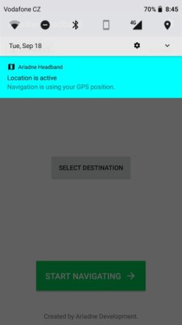
Project Ariadne Headband is made out of two parts: headband and Android app. The common usage flow is following. First, you open Ariadne Headband app. Using this app you connect via Bluetooth to your Headband. Next, the app will ask for you current GPS location. Then you open Google Maps integrated into our app and select your destination (place where you want to go).
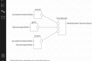
Our Android app will compute the geographical azimuth from your current location and chosen destination. When you are ready you start navigating by pressing a button that sends computed azimuth to the Headband you put on your head. Azimuth plus some other data are sent as a bytearray through Bluetooth Low Energy.
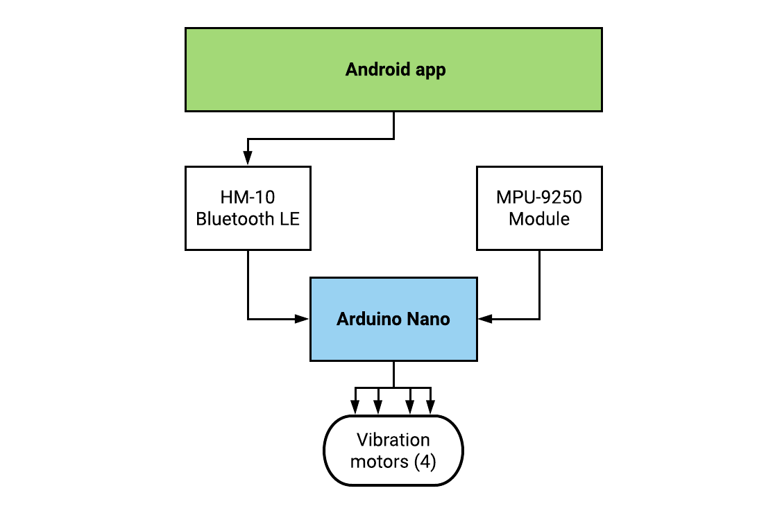
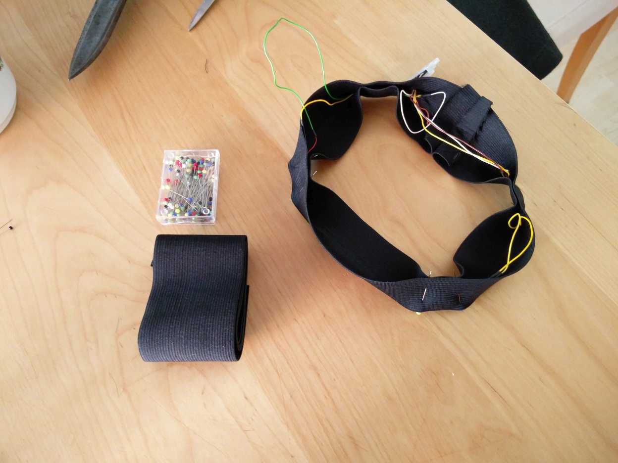
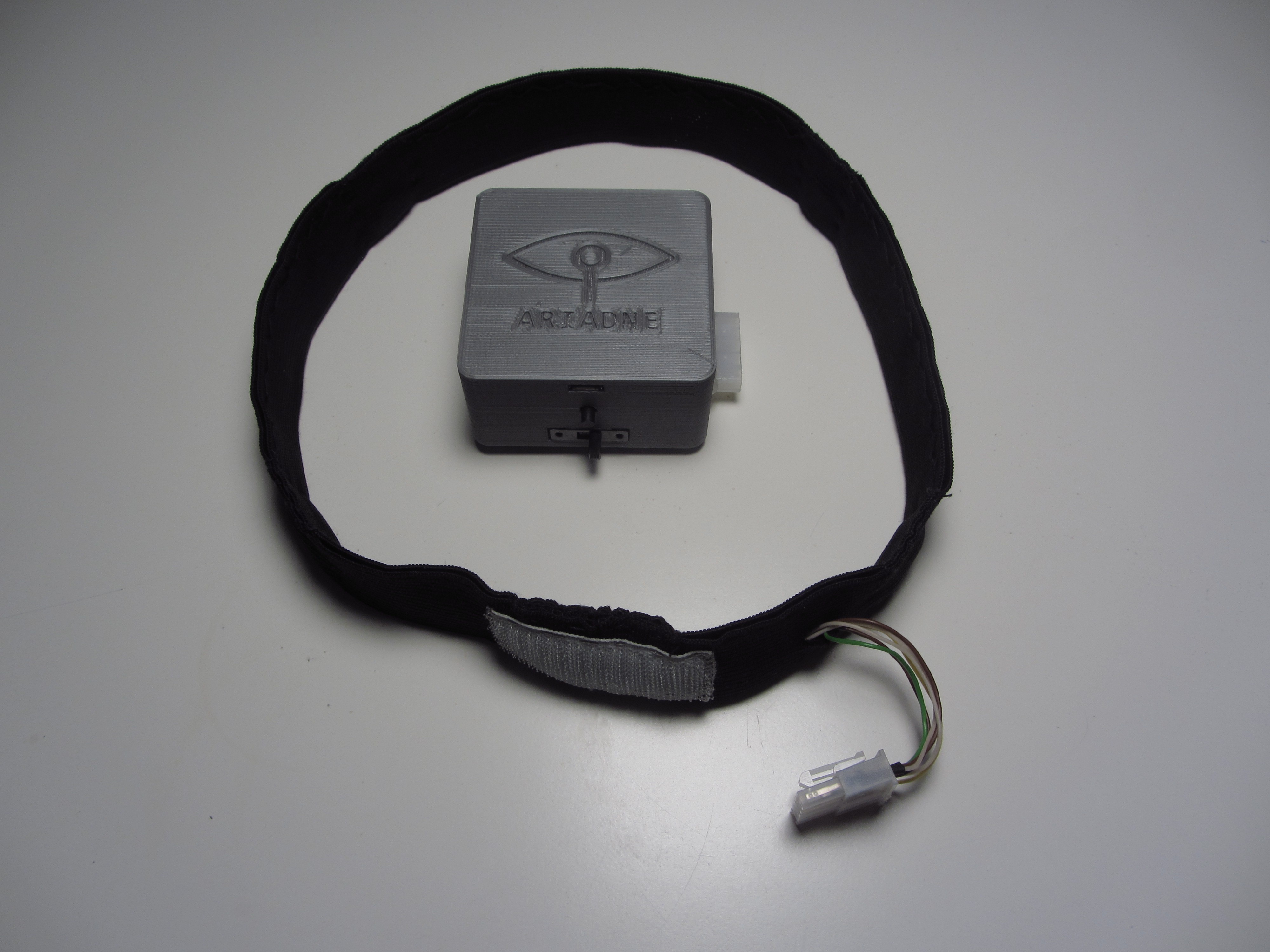
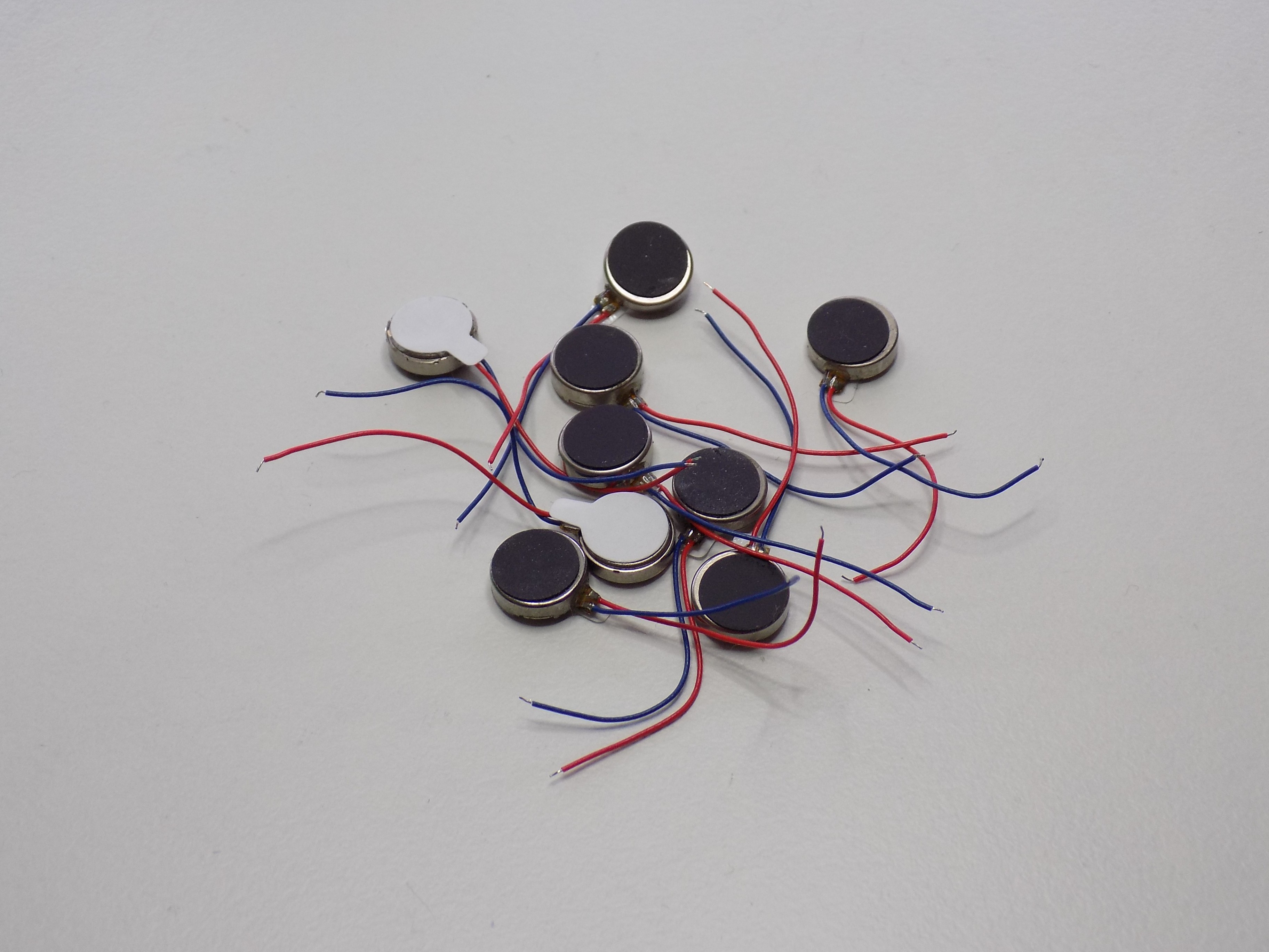
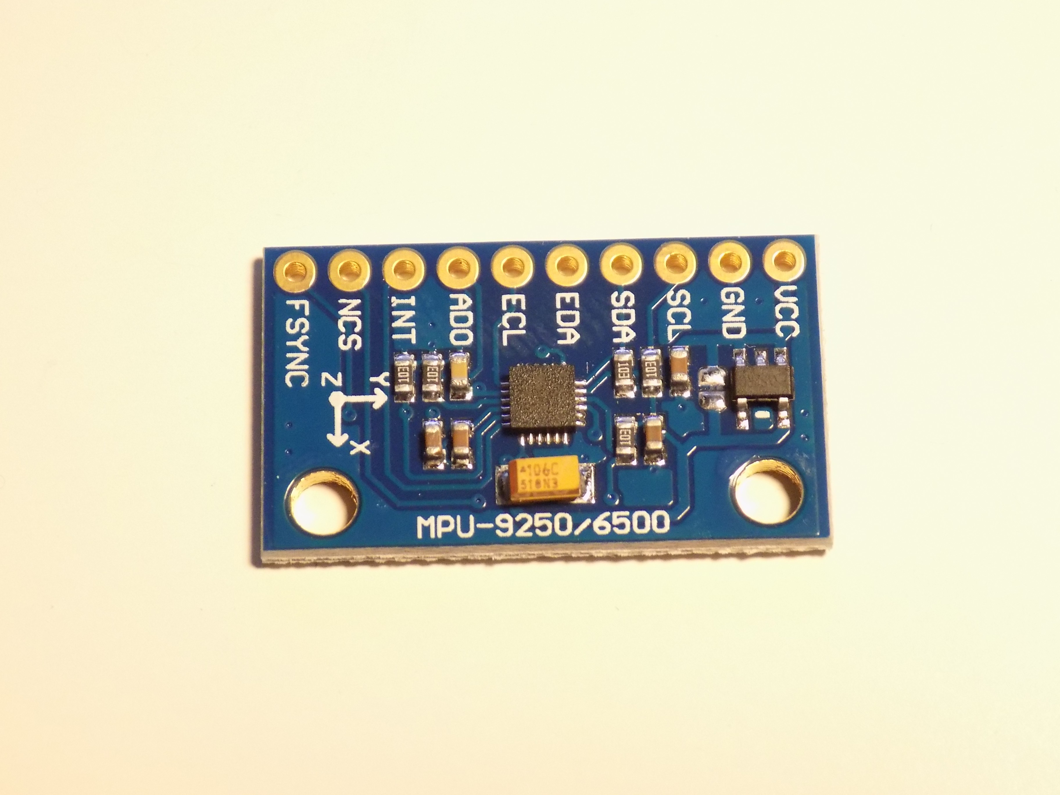
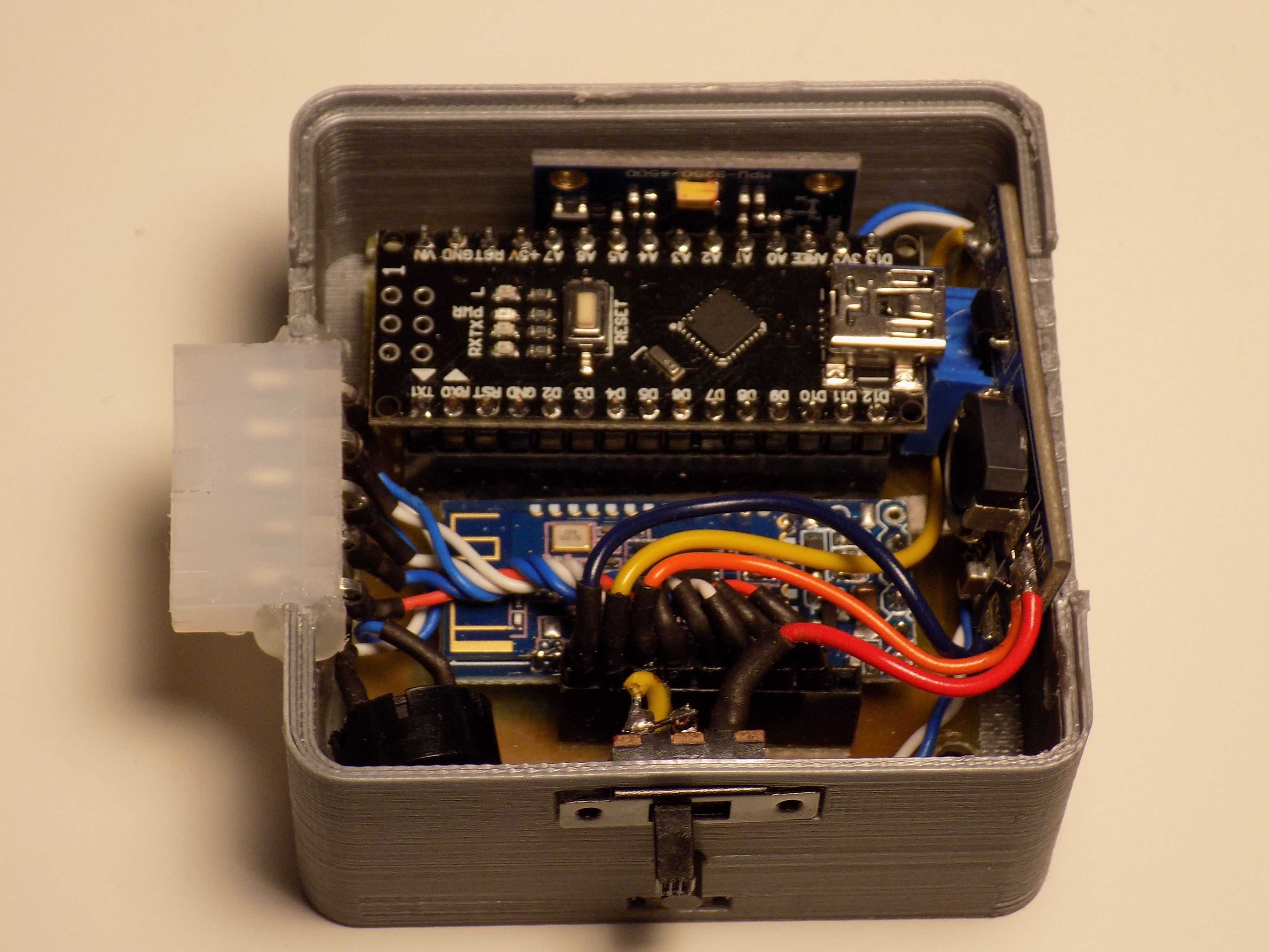
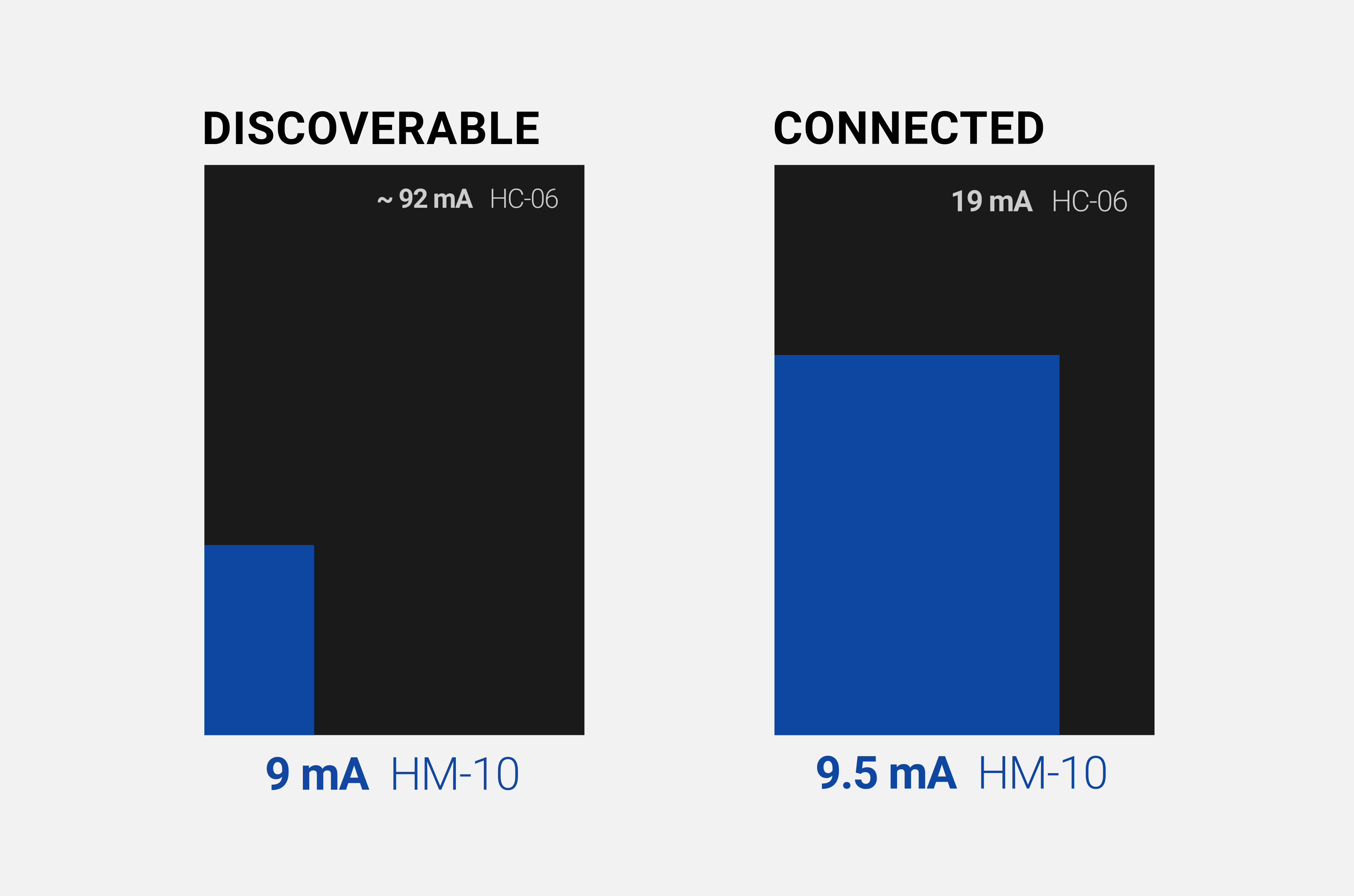
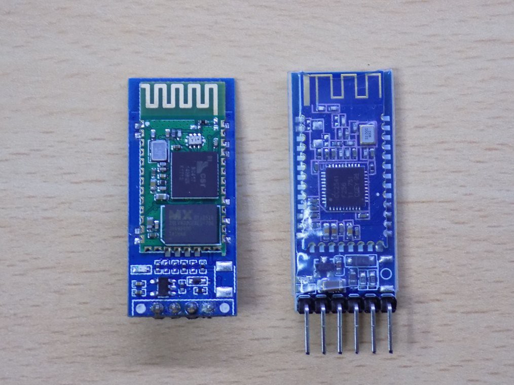
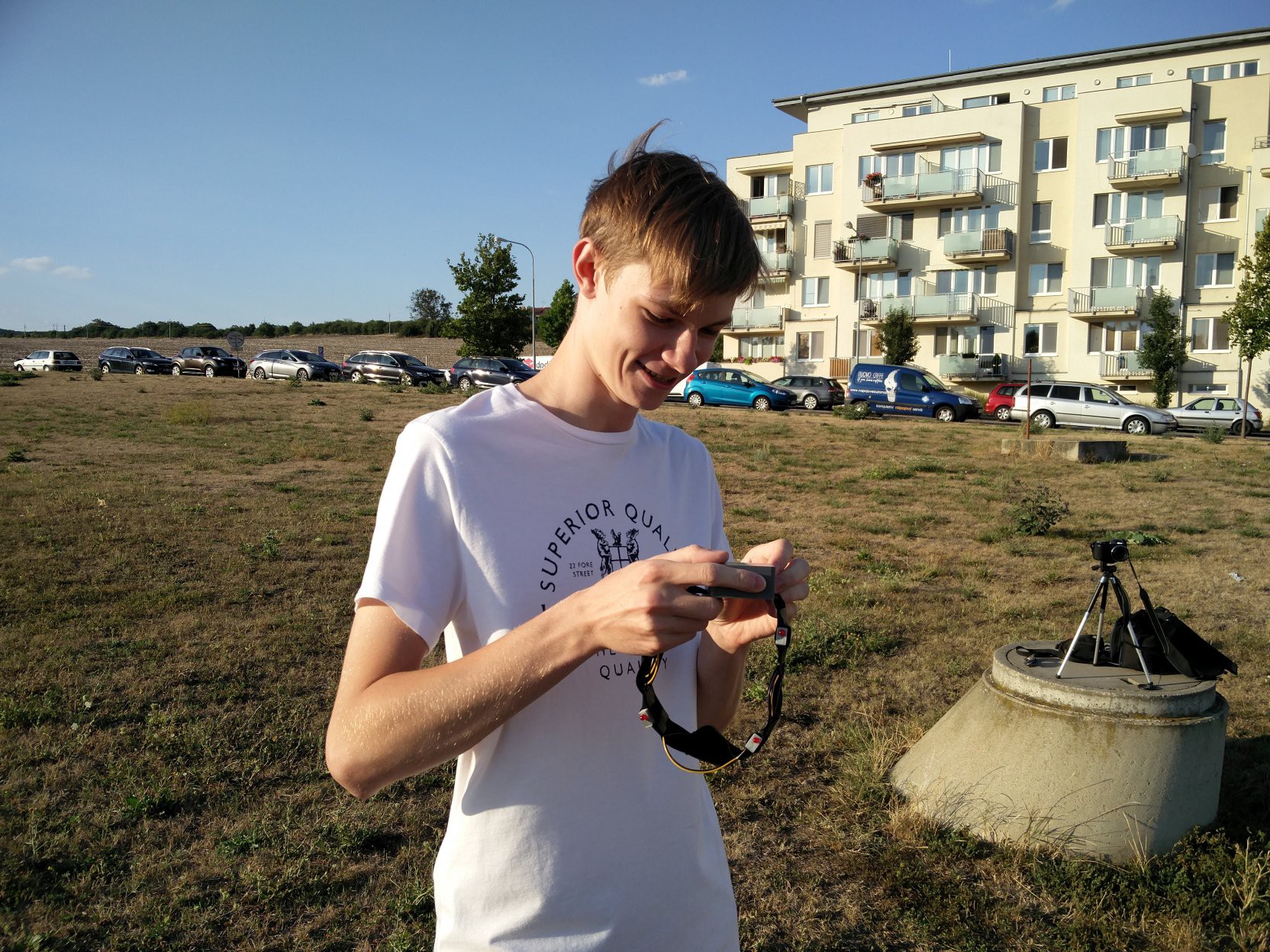
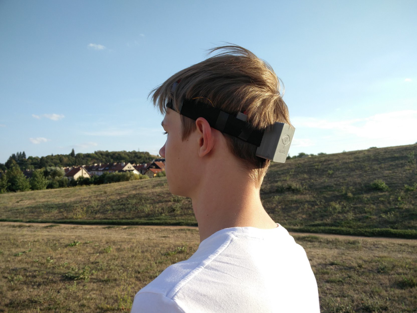
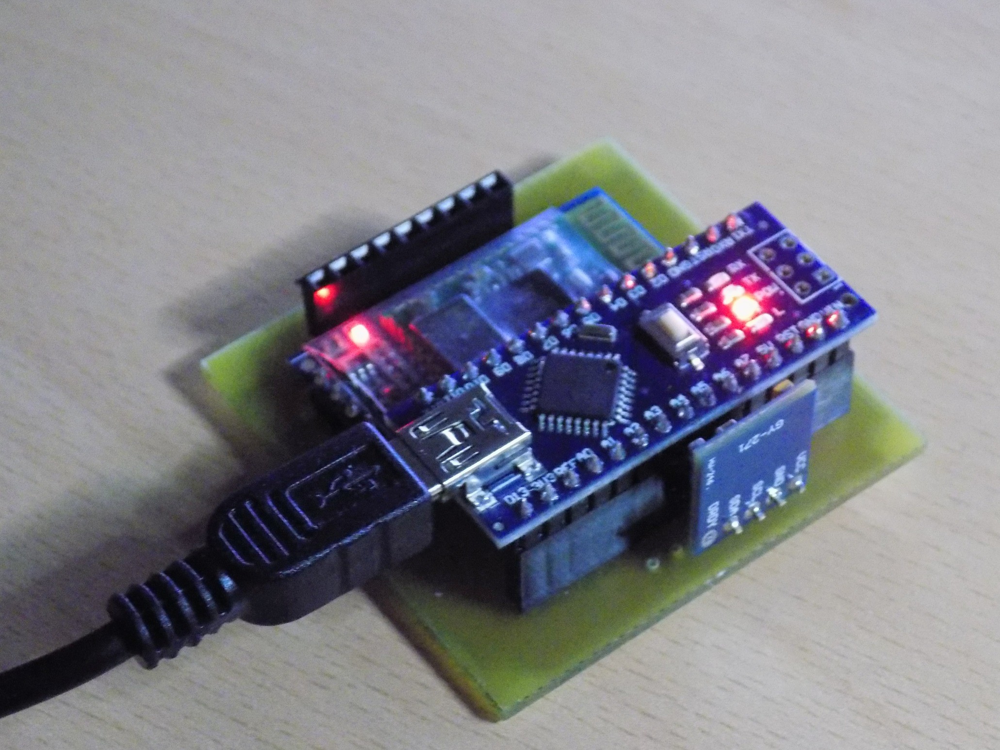
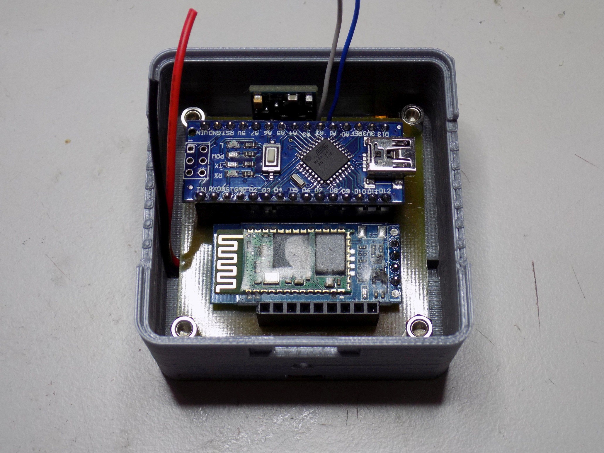
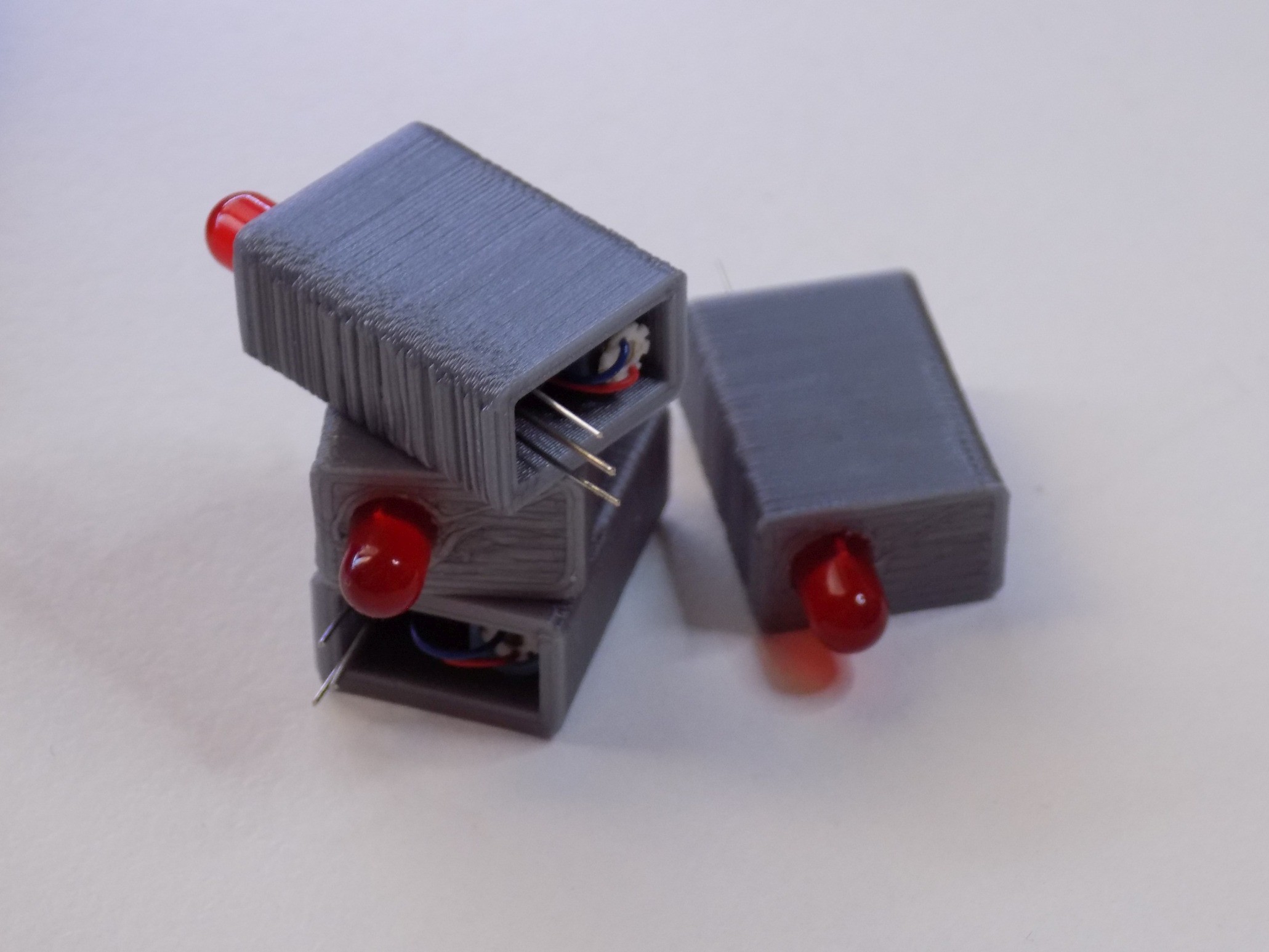
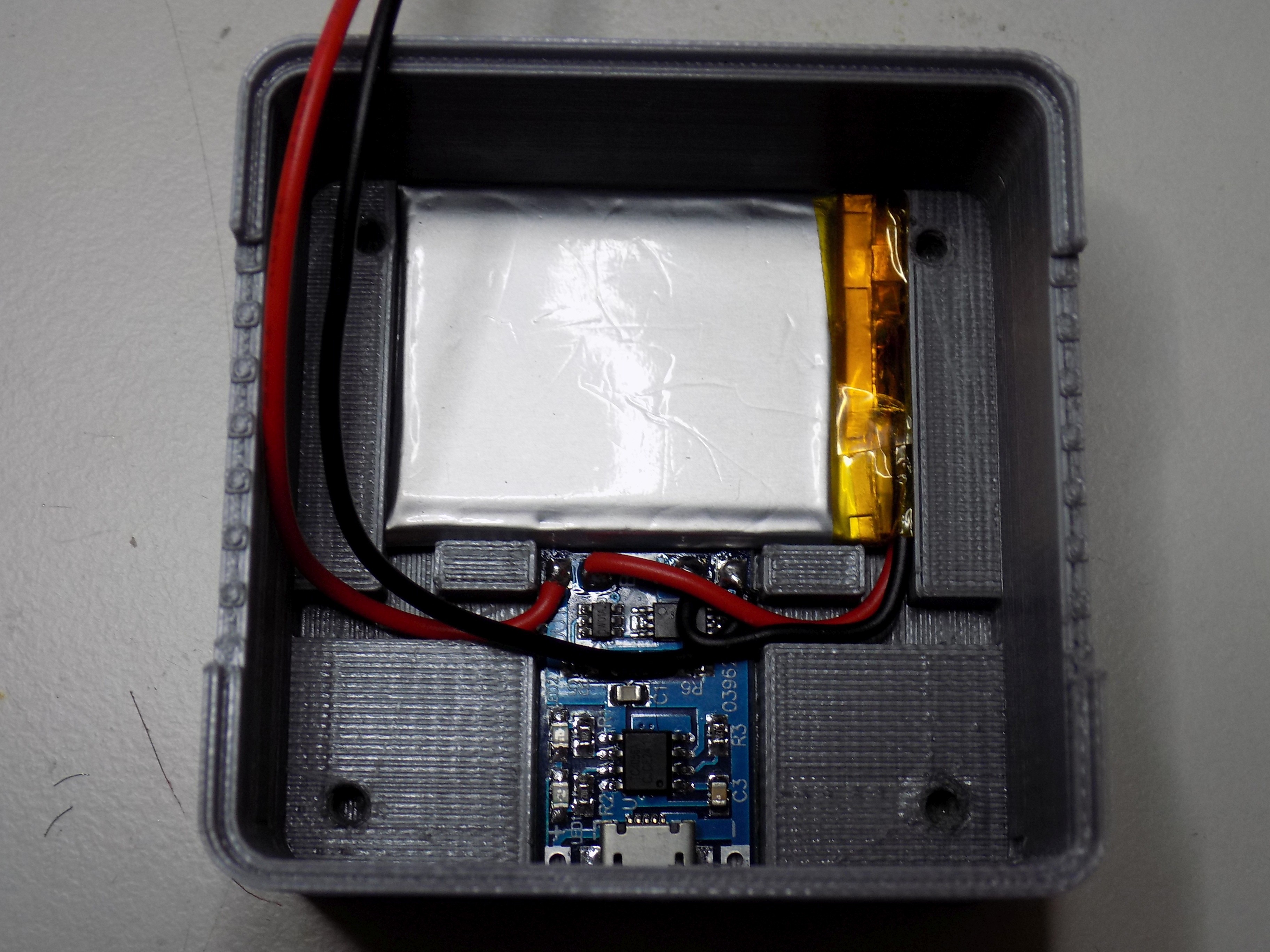
Headband consists of Arduino Nano board, MPU-9250 "compass" module, HM-10 Bluetooth Low Energy module and 4 vibration motors. Compass module allows us to know current azimuth, that is where is the user looking. All components are placed into a box on back of your head. Our aim in the future will be to make this as small as possible so you will not even feel it. It is also possible to place everything into a hat or helmet for example instead of rubber headband. We are using rubber headband because it is very easy to manipulate.
Vibration motors around your head are placed in set directions so they can signalize where you should head. Your heading is computed by taking your current azimuth and the azimuth sent from android app (that is where you are currently going and where you should go, respectively). See illustration below for Headband overview.
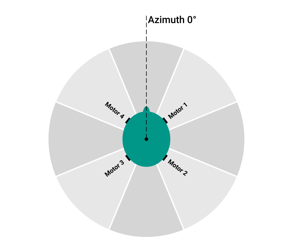
For example, Motor 1 is activated when you should head 45° (this is same for other diagonal directions). If you should head straight, both Motor 4 and Motor 1 will be activated. The similar approach applies for left, right and turn back signals. We originally planned to use 8 vibration motors, one for every 45° but have concluded that it would by more complicated and would not be worth it. The motors would be too close together and it would be hard to recognize right direction. Using 4 vibration motors is both cheaper and more robust.
Why is is useful?
As you might seen in a MythBusters scene or in few videos on YouTube, it is hard to walk straight when you cannot see. Blind people who use cane have to find some guideline, pavement for example, or use guiding dog. Otherwise it is not easy for them to keep right direction. For the other cases, some people like runners usually do not want to stop and look on their phone where they should head.
... Read more »


 hrkltz
 Marius Slavescu
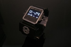
 Mar Bartolome
 nGoline