Frank Buss
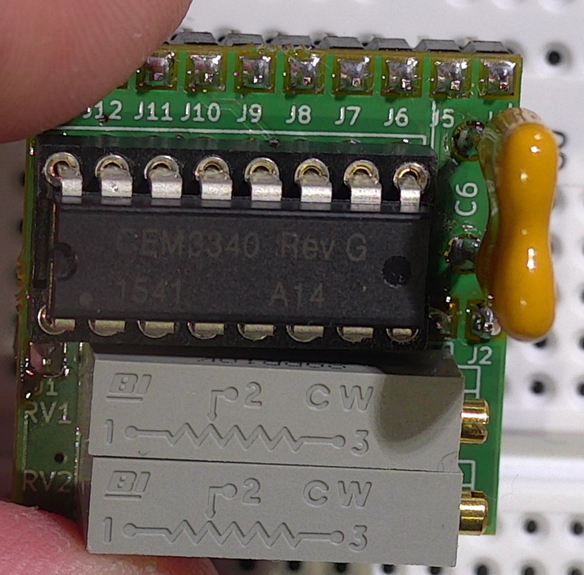
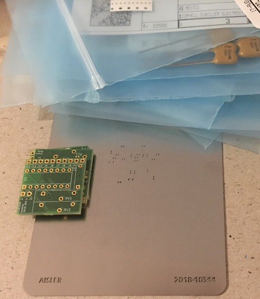
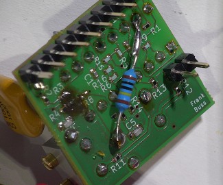
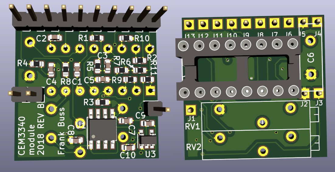
This module makes it easy to use the CEM3340, which needs quite some external components by itself. With this module all you need is a dual power supply with +12 V / -12 V, which you might already have if you have an Eurorack, then a breadboard, a few wires and a 10 k potentiometer to test it. You can order the board, a stencil, and all parts (except the CEM3340) from Aisler. You can order the CEM3340 from Thonk.
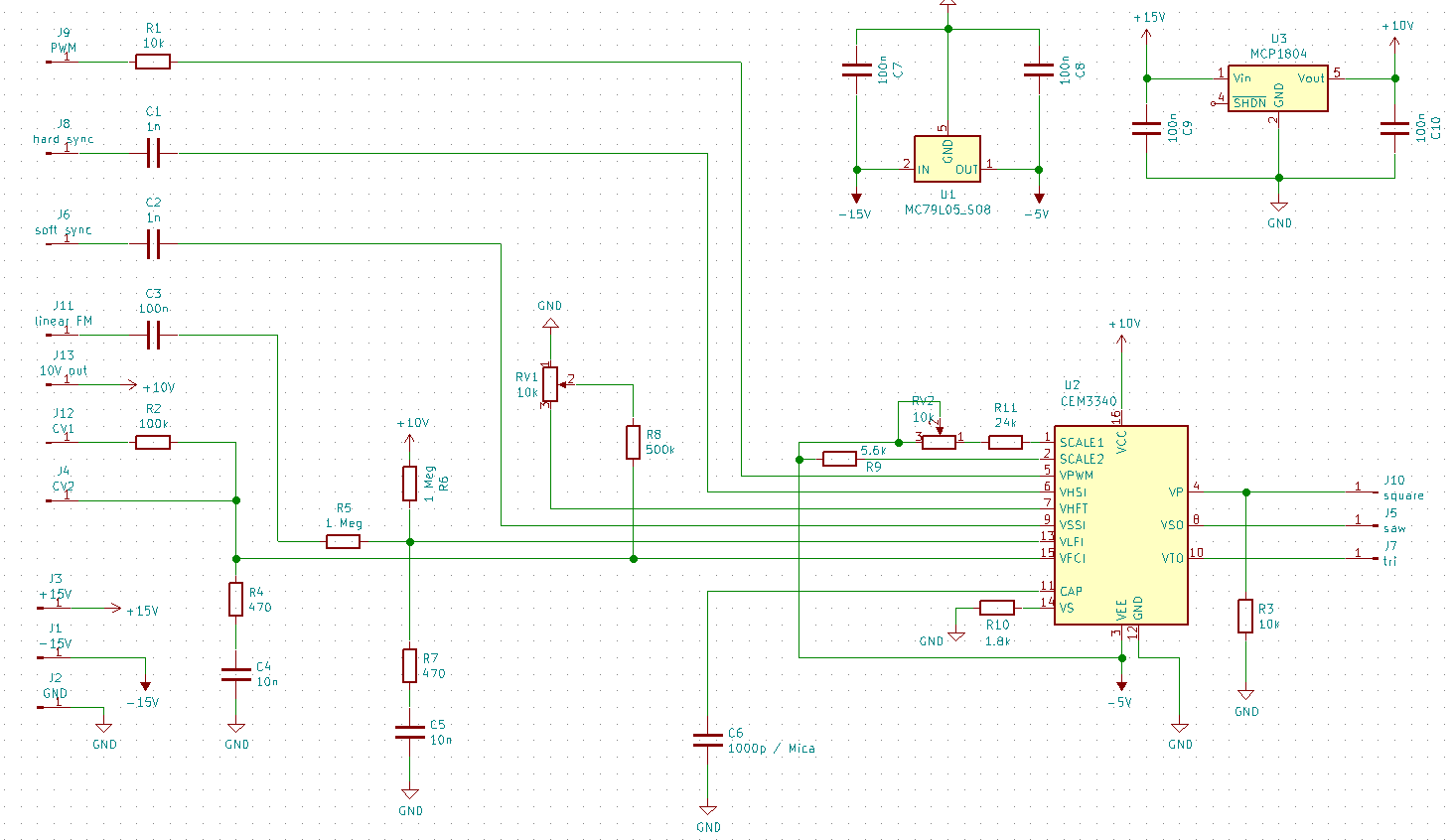
In the files section you can find the datasheet of the CEM3340 and the KiCad files for the circuit diagram and the board layout. In the Gerber directory are the Gerber files, if you want to order a board.
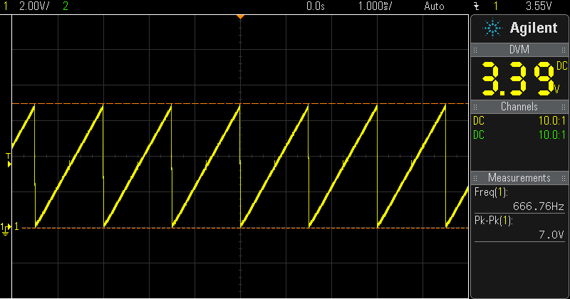
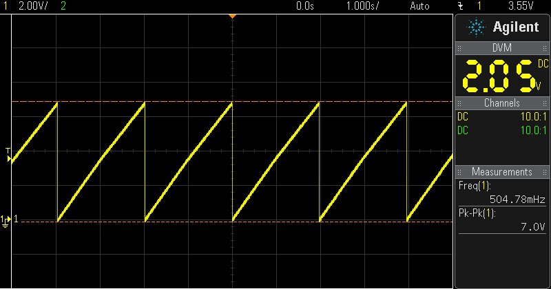
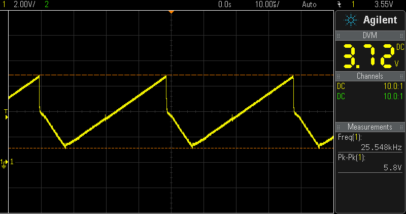
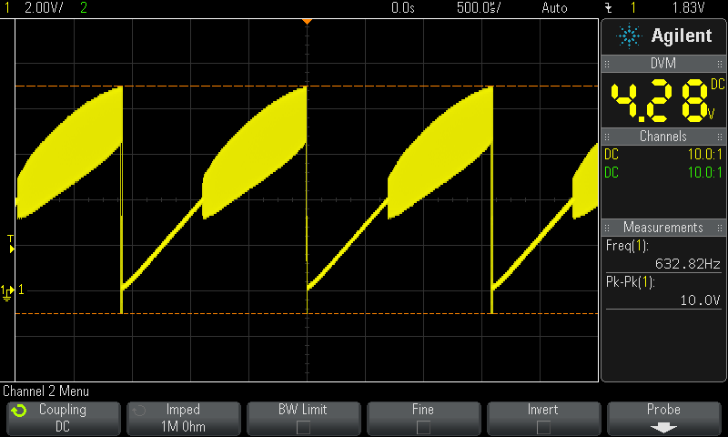
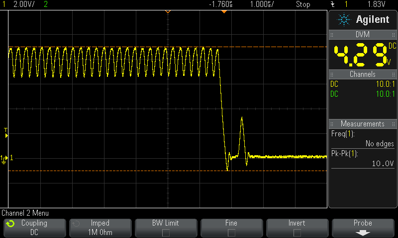
After soldering the board, connect J3 to +12 V, J11 to -12 V and J2 to GND (+15 V / -15 V is also possible). Then connect the soft sync input J6 to GND, connect a 10 k potentiometer from the +10 V output at J13 to GND, and the slider of the potentiometer to J12. At J5 is now a sawtooth signal. You can change the frequency from about 0.5 Hz to 680 Hz.
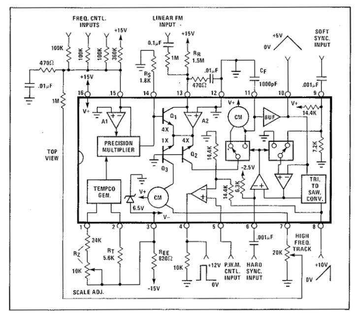
The CV input at pin 15 of the CEM3340 is a current input. This means this pin is a virtual ground inside the chip and you can just add multiple external currents to it. The J12 input uses a series 100 k precision series resistor. This converts an external control voltage (CV) to the current CV/100k.
The pin J4 of the module is directly connected to the pin 15 of the CEM3340. You can either use another external 100 k series resistor, to add another CV, or you could just add some offset current. For example if you connect J4 with a 180 k resistor to the 10 V output at J13, the range of the external 10 k potentiometer is from about 62 Hz up to 54 kHz.
The CV input is an exponential input with volt/octave behavior. This means, if you increase the voltage by 1 V, the frequency is doubled. Use the calibration procedure explained in the datasheet on page 5 for the two trimmers to adjust the exponential accuracy for the lower frequencies (RV2) and the higher frequencies (RV1, starting at about 5 kHz). Read the rest of the datasheet for more information about the other inputs and outputs.
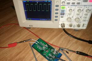
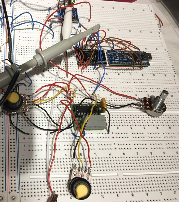
Testing on a breadboard:
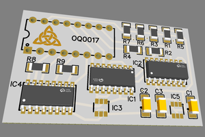
The additional components are an Arduino Nano and a DAC in the middle, not used at the moment, but I plan to implement something to use it as a MIDI receiver (MIDI-2-CV). At top is an op-amp, which buffers the output signal of the CEM3340, because it can't drive much load. With a 330 ohm series resistor and a 10 uF capacitor, the op-amp can drive a small speaker.
Some devices have a volt/octave CV output, like the Beatstep Pro. You could just connect this to the CV input at J12. Then add an envelope generator for the trigger output, maybe with a VCA like the V2164, and you would have a fully monophonic synth.
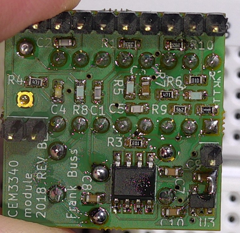
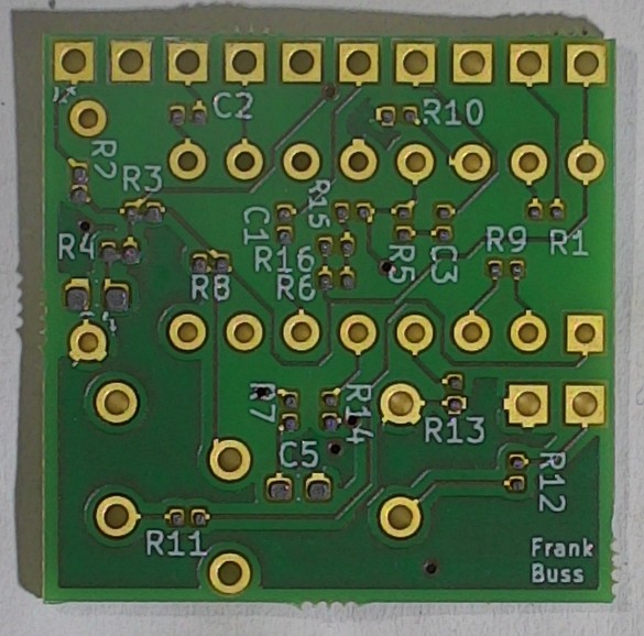
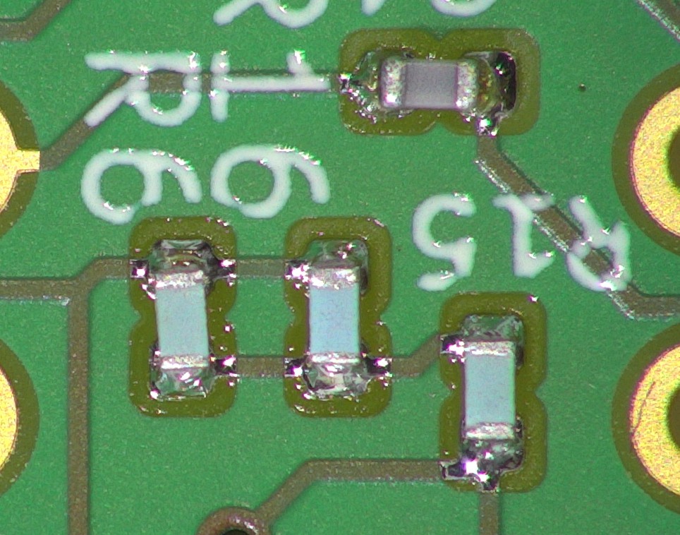
Some remarks for the components selection: Most capacitors are C0G capacitors instead of the cheaper X7R version, because they exhibit a lower microphonic effect (inducing a voltage when you tap them) and the capacity doesn't change as much with the applied voltage, as with X7R (doesn't matter for the 100 nF capacitors, because they are just for the voltage regulators). For the resistors I chose low tempco types, so that they don't change much when the temperature changes, which is always a problem with analog synths. The value of most resistors are not critical, but the 100 k resistor for the CV input should be very accurate (0.5 % or better), if you plan to add more summing inputs with external resistors, which then should be as well high accurate 100 k resistors. And finally the 1000 pF capacitor is the most important part, determining the quality of the oscillation. Therefor I used a Mica capacitor, the best you can get regarding capacitors (meaning it behaves as best as an mathematically ideal capacitor as possible) and which is recommended in the CEM3340 datasheet. But a cheaper modern film capacitor might be possible, too.


 macafeeje
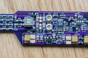
 Bud Bennett
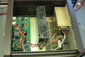
 Quinn
Quinn