Close
0%
0%

uMesh

A 1" squared ESP32 module that natively takes LiPo batteries, charges them, and doesn't kill them.

Similar projects worth following
An ESP32 module.
Included is a lithium battery charge circuit, lithium protection circuit, power supply, and antenna, all in a 1 inch by 1 inch package.

The goal is to have a tiny, inexpensive module that can immediately accept a battery and be deployed in the field, along with 30 of its mates.

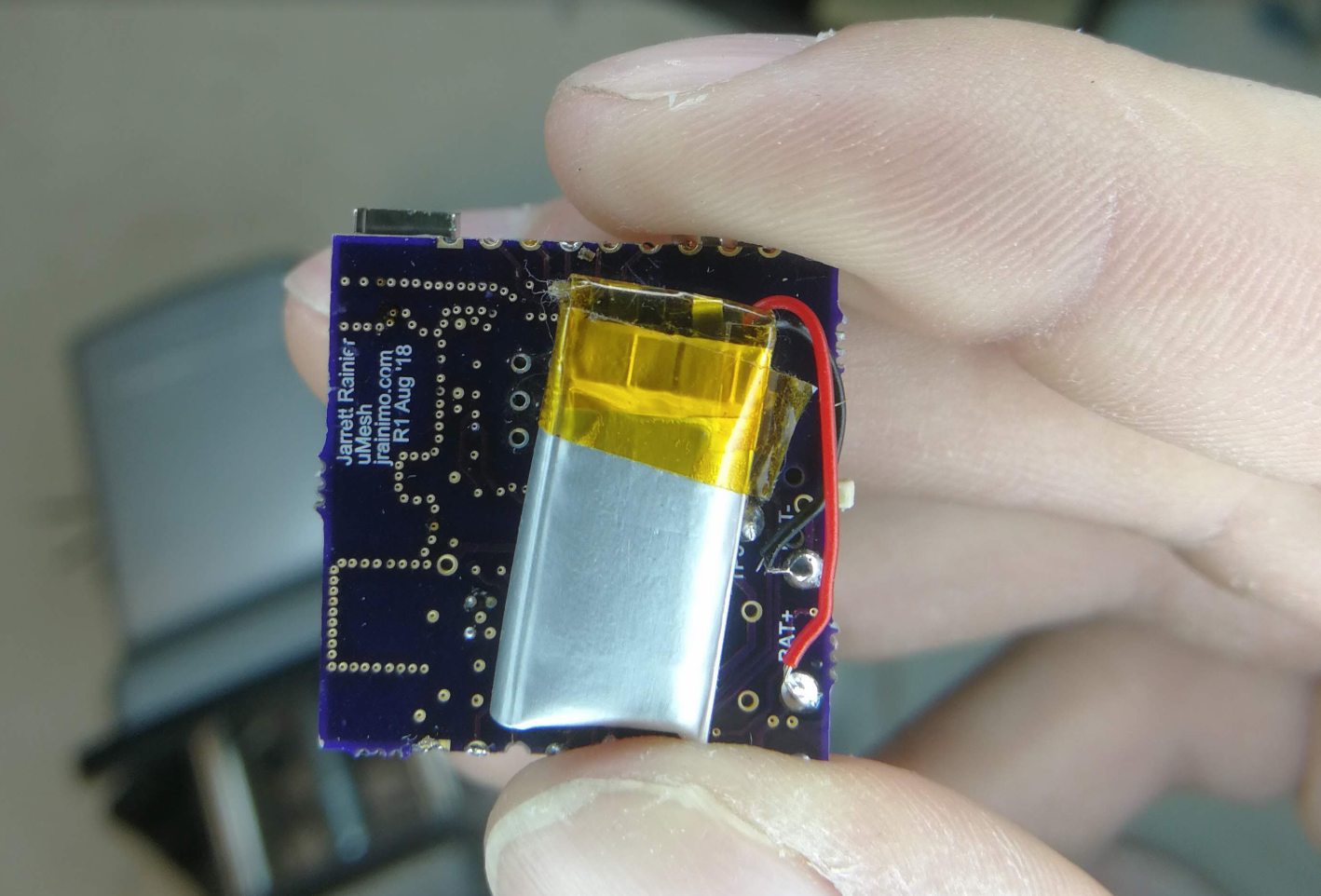
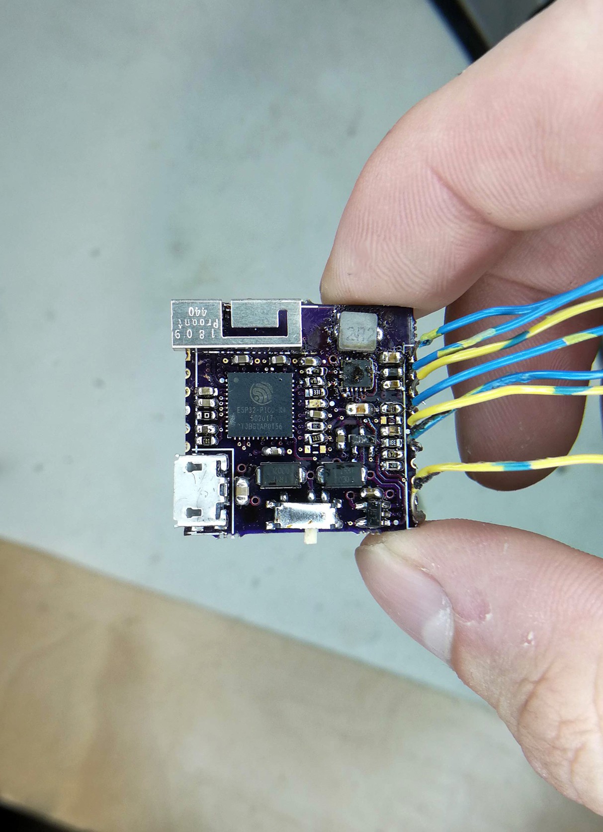
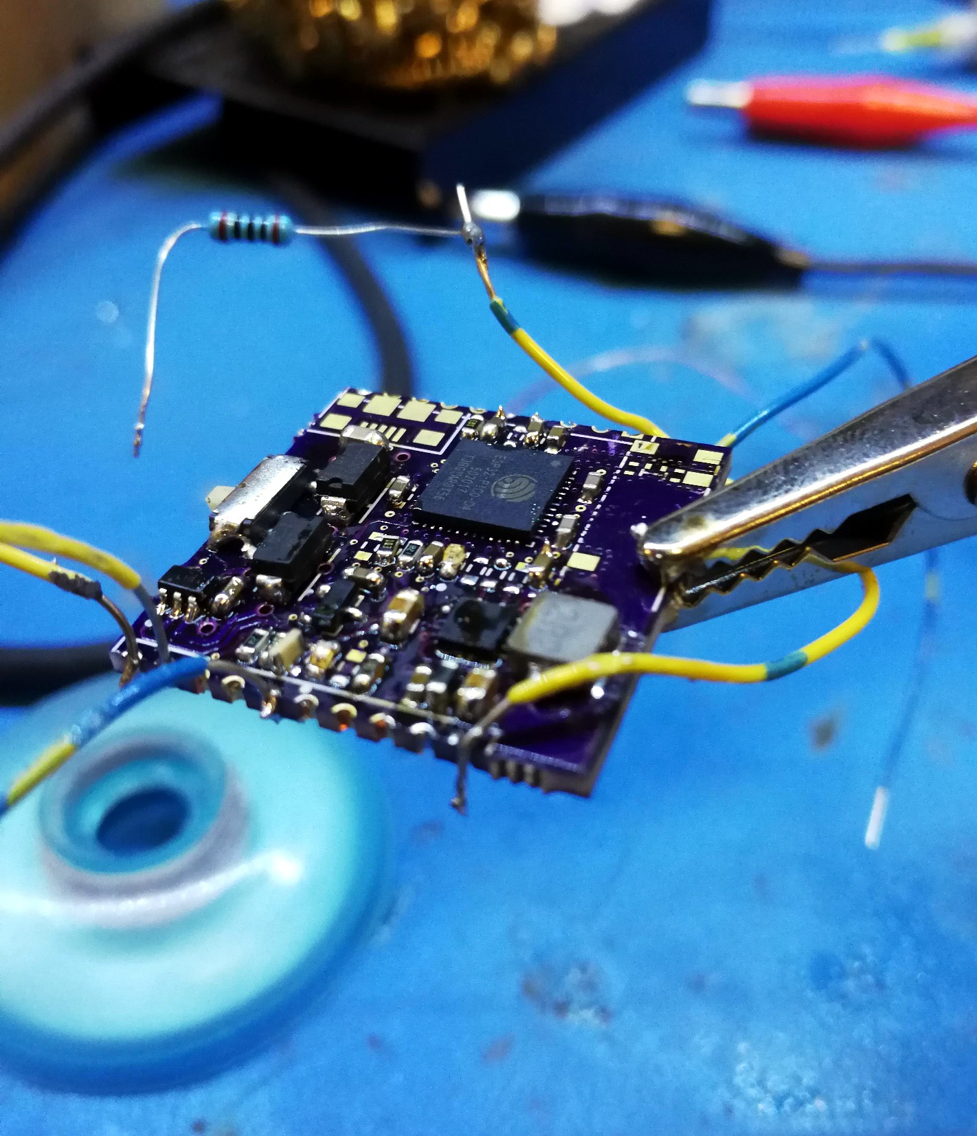
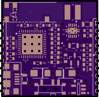
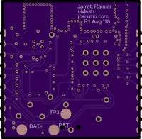
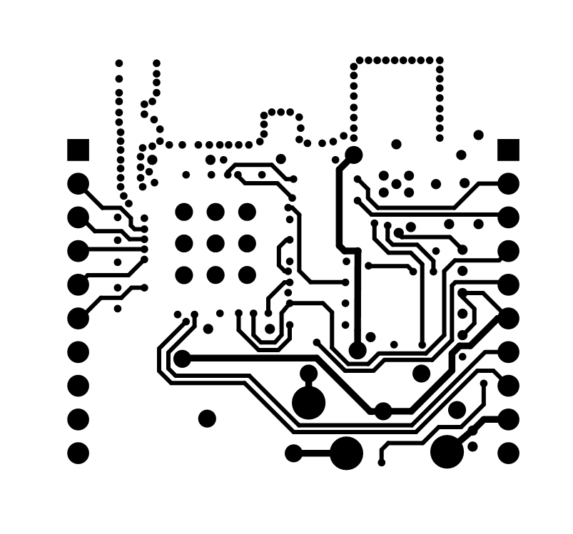
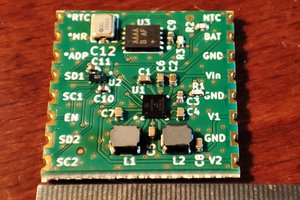
Part of the problem I've been seeing with inexpensive IoT dev boards, is that the design around the power system hasn't been very good. Here's my attempt to fix that. This is a battery-ready module with a proper lithium battery charge circuit, lithium battery protection circuit, power supply, and antenna, all in a 1 inch by 1 inch package.

The battery/power circuitry is surprisingly complex, which is why the built-to-a-price-point applications often don't have the "proper" battery control, opting instead for "good enough".

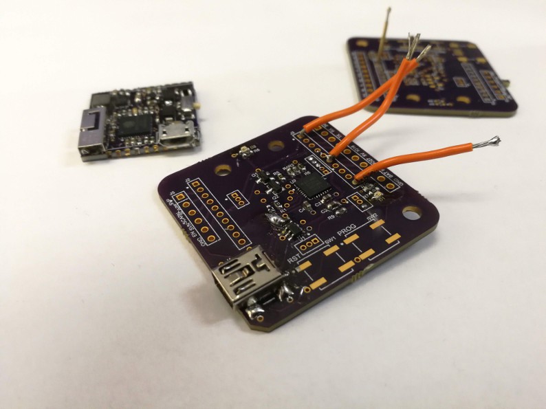
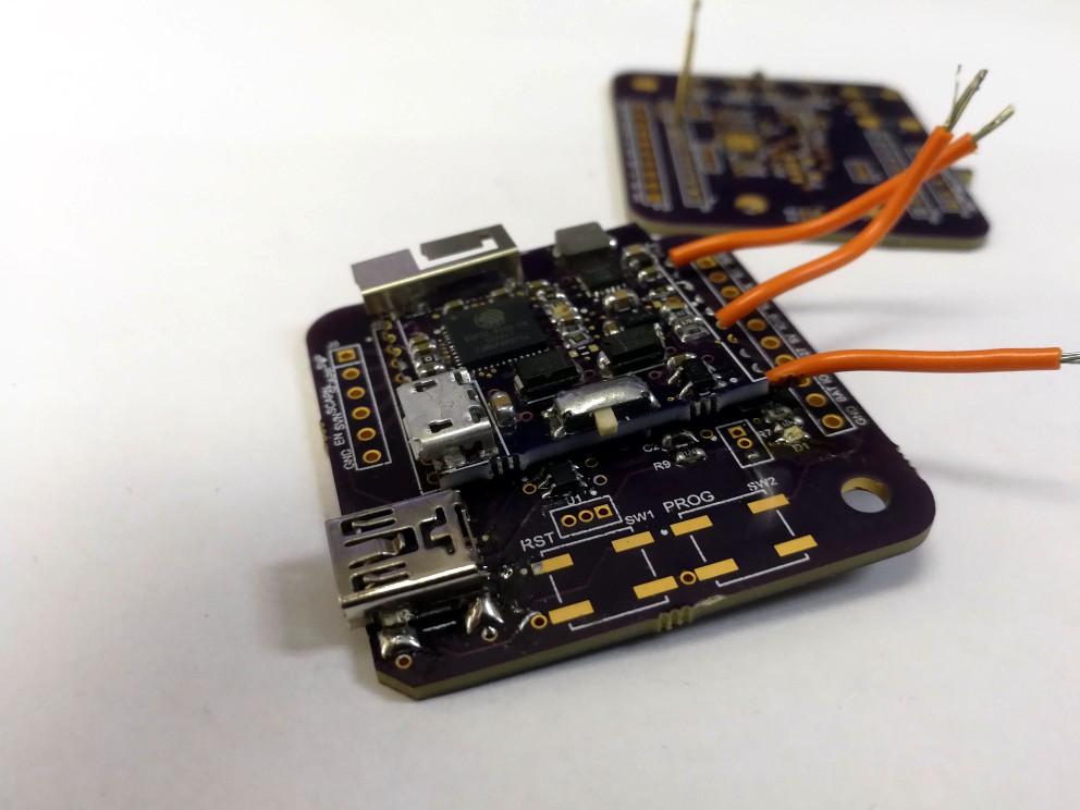
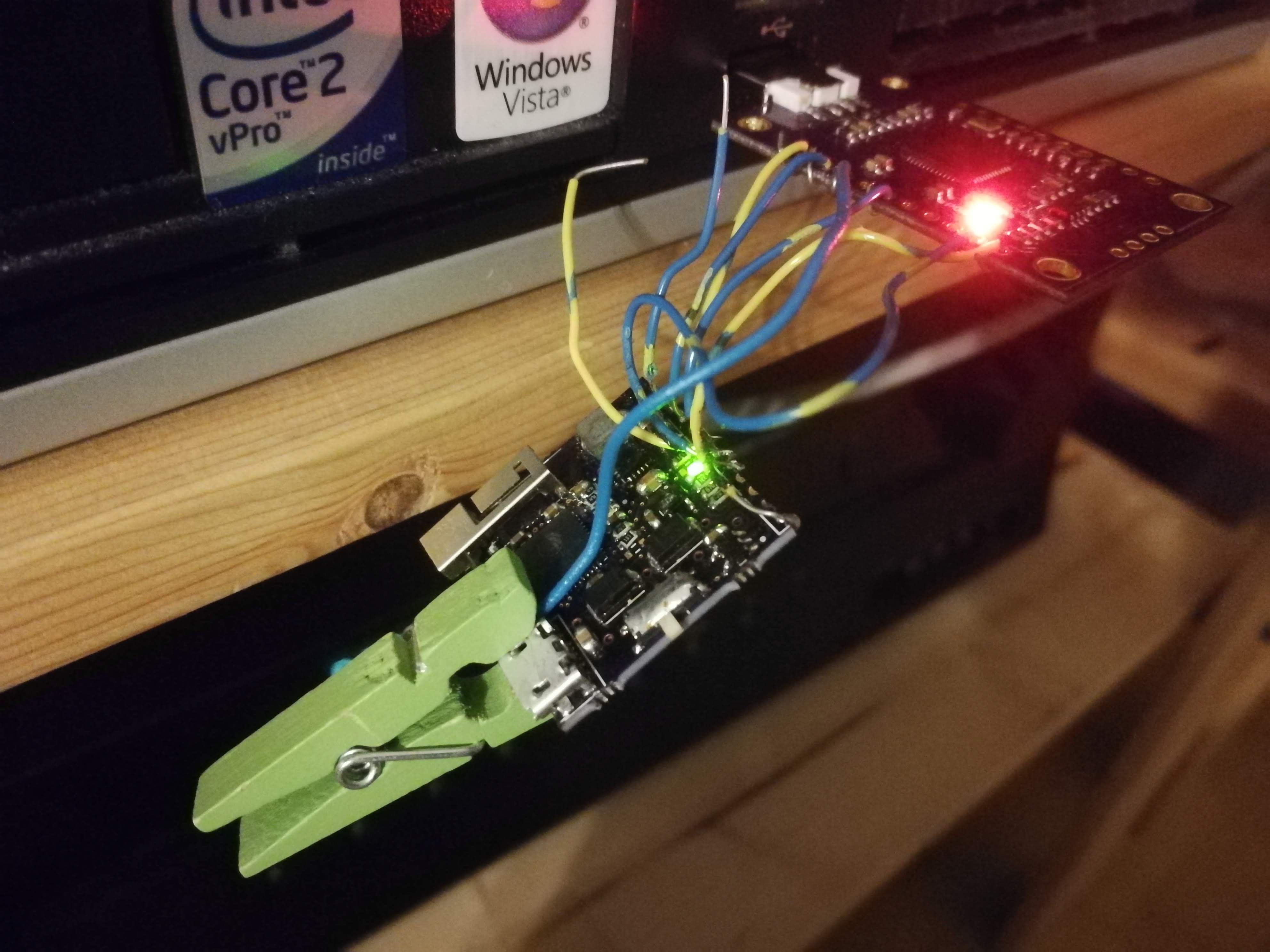
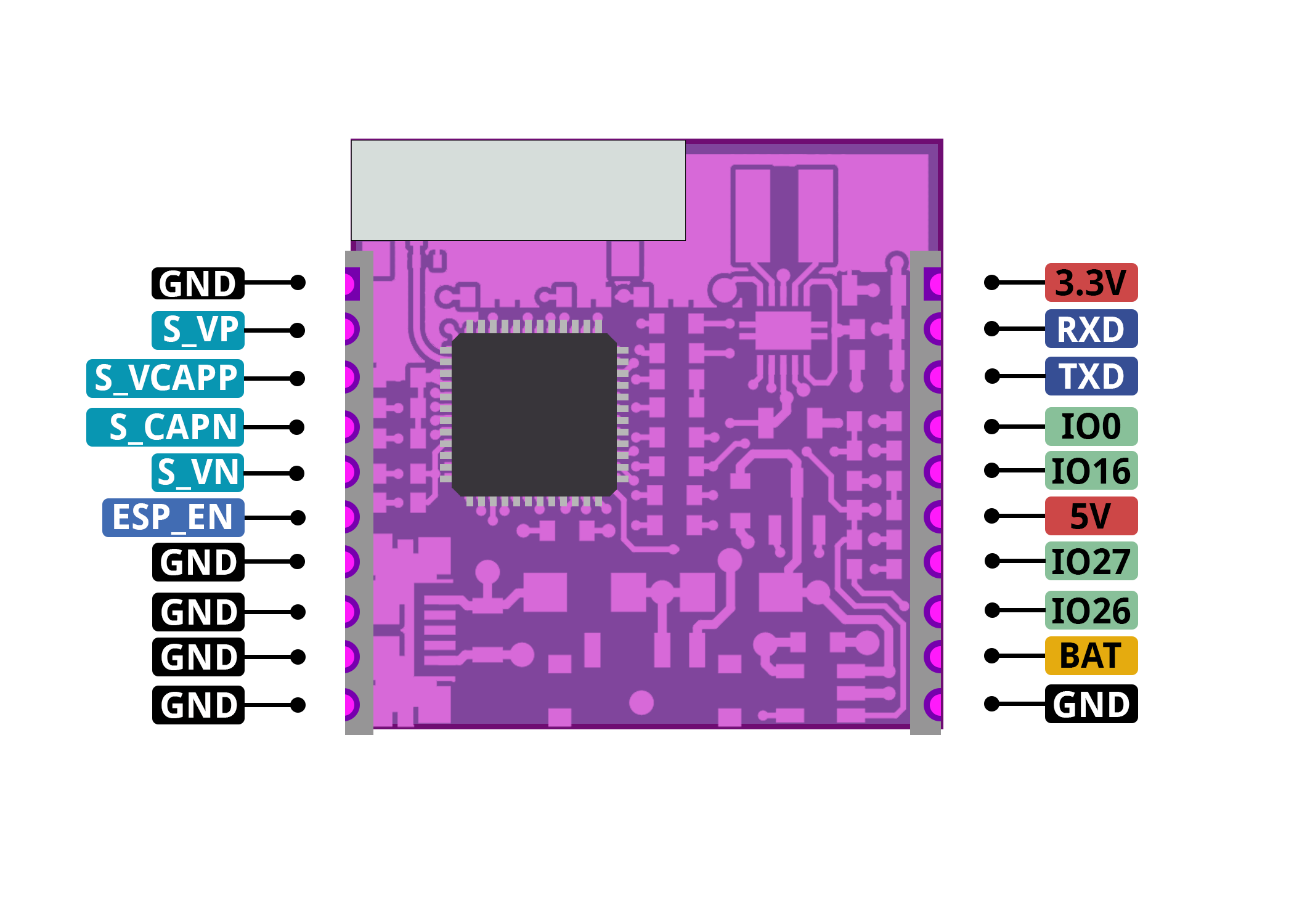
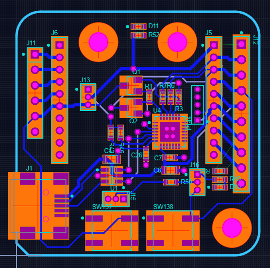
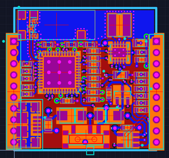
The main interface to the world (other that WiFi or Bluetooth) are castellated headers on the left and right side. Those grant access to input voltage, battery voltage, output voltage, TX/RX pins, bootmode selection, and a few GPIO. Because of them, this module can be soldered directly down to a larger host board if necessary, and can even provide regulated 3.3V output to it if given battery power.

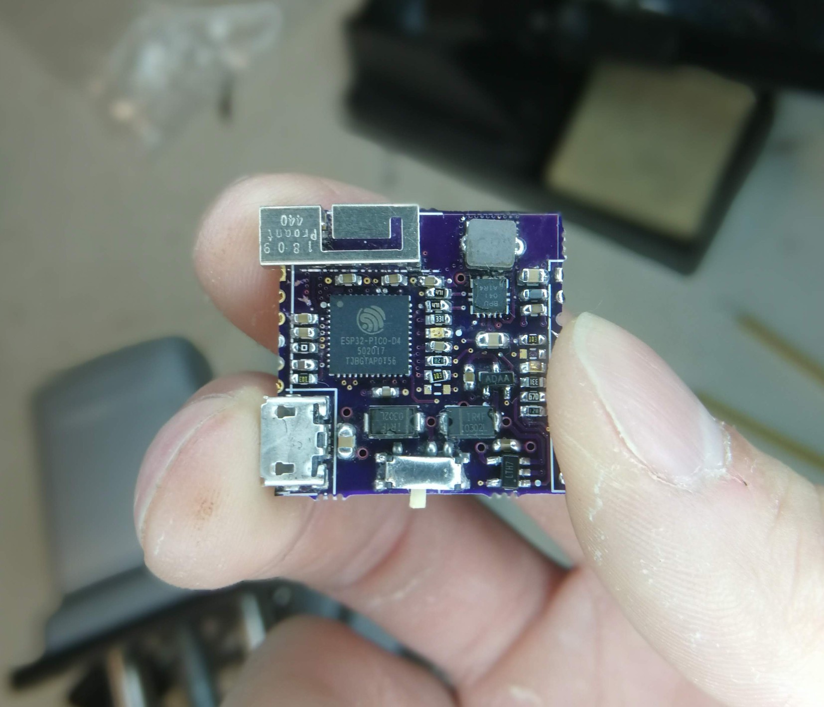
What sets this apart in terms of battery handling are a few things:

  • There is a buck-boost power supply to provide a constant 3.3V to the ESP32 through a battery's entire range (3.0V-4.2V)
  • There is a cut off for battery when it hits 3.0V, to prevent over discharging it
  • When the module is plugged in (through castellations or through the USB connector), it will switch over to using that as a power source
  • Also while plugged in, there is circuitry for constant-current/constant-voltage charging of the battery

x-zip-compressed - 466.94 kB - 10/01/2018 at 16:22

Download

tests0-1.zip

Test programs for bring-up

Zip Archive - 795.91 kB - 09/20/2018 at 18:00

Download

Assembly Docs - uMesh - 1.0.pdf

Detailed bring-up and test plan

Adobe Portable Document Format - 1.05 MB - 09/07/2018 at 19:01

Preview
Download

  • 1 × PCB - https://oshpark.com/shared_projects/flPqUN33 Electronic Components / Misc. Electronic Components
  • 1 × PRO-OB-440
  • 1 × 0402 1.6nH Inductor
  • 1 × 4mm 2.2uH Inductor
  • 1 × 0603 800 kOhm Resistor

View all 23 components

  • Programming Better

    Jarrett10/26/2018 at 23:06 0 comments

    Still not finished, but I'll write about what I have.

    I built up, mostly, the programming sled that I'd designed earlier.

    As you can see, it's still in "test mode" orange wire bodgery. Those inner, long rows of headers are intended to accept some pogo pins (shown in the back of the picture!) for the uMesh to be pressed down onto. Outer, more standard 0.1" headers are provided for whatever else someone might want, especially if they want to solder both boards and use as a complete package.

    As an extra-special bonus, those tiny inner headers match the programming pins of an ESP-WROOM-32 module! Just like the uMesh, you could choose to put pogo pins on that one, and press it down on this sled to be programmed.

  • The Other Side

    Jarrett10/01/2018 at 18:27 0 comments

    Here's the backside, with a battery soldered onto the pads. This will take any size of (single cell) LiPo, but charging current is set by a resistor, so that will never really change by an end-user.

  • Programming

    Jarrett10/01/2018 at 16:20 4 comments

    How do you program your module if your programming sled is not yet complete?

    Oh, don't ask, it's awful.

    It blinks!

    Over the next couple weeks, I'll go into tuning of the antenna, and errata I found while building it, but all of that is just icing.

  • Pinout Diagram

    Jarrett10/01/2018 at 02:28 0 comments

    Huge shoutout to @-= Wolf =-  for drawing the pinout diagram for me!

    He did an awesome job!

    Sometime later, I'll get around to doing a title block and legend and all the good stuff that those Arduino variants have, but this is more than enough to get people prototyping!

    This is also information that is available in my mammoth hand-assembly doc, but it's much more accessible here for end-users.

  • Assembly is complete

    Jarrett09/29/2018 at 02:27 0 comments

    Testing still to come!

    The gummy flux in the top right is bothering my more than I care to admit! Unfortunately, I won't have access to an ultrasonic cleaner until Monday, after the contest has finished. Oh well, that doesn't affect operation.

  • Bring-up Software

    Jarrett09/20/2018 at 18:34 0 comments

    I've written a few test programs that will help test out functionality as I bring everything online.

    They're in the zip file attached to this project.

    Currently, there are four programs. These are very much going to change as I finish bringing my hardware online.

    Blink blinks the onboard LED.

    Charge tests the battery charging circuit and reports back what the ESP32 thinks is going on with that (on battery power, charging, charged).

    RSSI passively scans all the network traffic in the area, and then reports back the signal strengths it sees. More on that in a sec.

    Speed, which hasn't been written yet, will connect to my home WiFi network and attempt to send data as fast as possible.

    From within the folders, run make flash && make monitor to start it all up.

    Naturally, the goal of those last two programs is to test my RF circuitry, including the stamped metal antenna. Right now, the RSSI program is running on an ESP32-PICO-KIT dev board, which also uses the same antenna. I'll run it again alongside my final uMesh hardware, but here are some preliminary results:

    The PTS (points) field is a good indicator of how much traffic my ESP32 is seeing, and then the power level is a rolling 32-point average of the latest samples. 

  • Bring-up Is Slow

    Jarrett09/11/2018 at 15:21 0 comments

    As expected.

    I've spent two evenings on this, and it should take one or two more.

    Going through the prepared assembly plan line by line and not really having to think about it is waaay easier than just ad-hoc building.

    Everything is also quite tight! I full expected this.

    Fortunately, I have a microscope.

    It's helpful, although a binocular microscope would be boss.

    I expect the next two days of assembly to look like this:

    Next time, finish the last of the support circuitry for the ESP32 itself and power it up. Flash with my test programs.

    Final day: Antenna assembly, testing, tuning, and reassembly.

  • The Bring-Up Plan

    Jarrett09/07/2018 at 18:29 0 comments

    After finished a PCB design, there are three blockers in terms of time before I can start bring-up:

    1. OSHPark fab and delivery (this took about a week from order to my door: mindblowing)
    2. Digikey parts order (Usually about 24 hours: also amazing)
    3. Me clearing my schedule to make it down to the lab (still hasn't happened yet)

    The waiting is annoying, but even more so when it's entirely on me!

    I have had lots of screen-time though, even if I haven't been able to physically make it to a soldering station.

    So in the meantime, I've written detail documentation and a bring-up test plan for the uMesh module. It clocks in at 17 pages currently, and I'm sure I'll be adding to it as I work on it.

    I'm adding it to the files section of this project.

    I should also mention that I'm stoked about the deadline extension for the square inch project!

  • A Programming Sled

    Jarrett08/27/2018 at 23:46 0 comments

    Still a little bit of work to do, but this is the gist of it:

    A uMesh user can press the module down onto this sled.

    There are headers for the uMesh module's castellated edges, some more typical 0.1" headers more towards the outside for a user to do whatever they like with it, and, interestingly, also programming headers to plug a bare ESP32 module into. Specifically the ESP32-WROOM-32D, so people can use this as a module programming jig.

    There is a CP2102 USB-UART bridge and the standard programming circuitry to make up for the uMesh module having none of it. You just plug in through USB, drop your module onto this sled, and start programming. The buttons are there for if you're doing something special, but you shouldn't need them.

    One issue / feature / errata with this is that it doesn't have a 3.3V regulator on board. It takes 3.3V from the uMesh module when it's pushed on. I still have to ponder for a bit, if this is okay. It does mean using it with a bare ESP32 module would require someone to supply 3.3v externally, too.

    One possible solution is the CP2102 has some sort of internal LDO regulator. I'm not sure if I can use it, and it especially seems like a bad idea with the currents the ESP32 can pull. I'll hit the datasheet to see if it's viable, I guess.

  • PCB Sent

    Jarrett08/24/2018 at 20:29 2 comments

    I actually sent it a while ago.

    Here's the Upverter image:

    And, @oshpark render:

    So pretty. It is $10.30 for the 4 layer board - I assume the extra $0.30 is because the castellations increase the "effective" board area from the manufacturer's perspective, but the PCB is 1" x 1" I swear! :)

    Also for completion, here are all the layers.

    Top (Signal):

    Layer 2 (GND):

    Layer 3 (3v3):

    Bottom (signal):

    Obviously I'll release all design files when I'm done, but it doesn't do anyone any good until its validated.

    The boards are expected back around the 28th, and shipping might take up to a week. It's gonna be tight!

View all 12 project logs

Enjoy this project?

Share

Discussions

zyndram wrote 07/22/2023 at 09:59 point

it is compatible with meshtastic or https://reticulum.network/ ?

why not add 4-16 keys for typing message? I prefer charge one device (meybe with solar panel) not phone and this dev

  Are you sure? yes | no

David wrote 01/13/2020 at 23:05 point

Hello. 

Just a question.
What is the consumption in deepsleep mode of the card?
Too beautiful design. 

  Are you sure? yes | no

nickarpik1440 wrote 12/30/2019 at 22:08 point

hey jarrett where can i buy these

  Are you sure? yes | no

Tom Staels wrote 08/23/2019 at 11:42 point

Hi Jarrett, 

did you ever take this further? 

Are you selling these little gems ?

cheers,

Tom

  Are you sure? yes | no

Martin Fasani wrote 12/05/2018 at 13:31 point

Very nice. I would like to test one of those!

  Are you sure? yes | no

Kartikkman wrote 11/10/2018 at 04:48 point

Hi Jarrett ,  Nice Design
I was also working on similiar design with ESP32 PICO D4 but mine didn't work out !!
From your design ,I want to ask that why have you provided 3.3 V to VDD_SDIO pin ??

  Are you sure? yes | no

Jarrett wrote 12/02/2018 at 20:06 point

Hmm, according to datasheet, here:

https://www.espressif.com/sites/default/files/documentation/esp32_datasheet_en.pdf

On page 11:

As long as MTDI is low (and it is pulled low by default), then VDD_SDIO should be at 3.3v, although it's ambiguous whether it is okay to tie to the rest of the 3V3 externally.

I think you're right, and I should leave it n/c for next revision.

  Are you sure? yes | no

rudi ;-) wrote 11/05/2018 at 06:58 point

Hi Jarrett,

very nice Pico D4 Board.
how to get one or two or three?
what you think, do you have a small place for 8-pin 150 mil SOP ?

https://www.electrodragon.com/w/images/0/04/LY68L6400_0.3.pdf

best wishes
rudi ;-)

  Are you sure? yes | no

Jarrett wrote 12/02/2018 at 20:07 point

Hi Rudi,

I will have these for sale on Tindie eventually, but not for another few months.

That's a good idea, I think I can maybe save some space elsewhere and fit that in. I'll think about it!

  Are you sure? yes | no

Similar Projects

Does this project spark your interest?

Become a member to follow this project and never miss any updates