 recursinging
The goal of this project is pretty simple; Take the general functionality of your typical MIDI keyboard or control surface and implement it (robustly, and with low latency) in the form factor of a guitar. The motivation is a a little less straightforward. Three things:
- I wanted to wear it on stage while maintaining the freedom to move about.
- I wanted to make it myself.
- It didn't want to spend a fortune.
I like the form factor of a guitar because it can look quite traditional in a rock band context, but upon closer inspection is clearly not. This reflects my taste in music, superficially recognizable, but substantially deviant. While I can play the guitar, I didn't feel it necessary that a functional guitar be augmented with MIDI controller capabilities, unless the two can be seamlessly combined. This is primarily because my single-threaded brain just cannot effectively handle playing an instrument well, while controlling other parameters.
Because a guitar hangs down in front of you, facing out, visual controls and feedback are pretty useless. A touch screen on the front of the guitar for example, is effectively a touch-pad for the player and a light show for the audience. Therefore I am mostly interested in tactile type sensors which can be blindly interacted with.
The DIY approach is simply an excuse to get lost in the details of interesting technical challenges instead of practicing, or composing actual music.
Regarding limiting cost... Yeah, anyone who has ever attempted a DIY project like this knows it's actually BS. There is no competing with the economies of scale that a market product has. We DIYers like to trick ourselves by spreading the costs into tiny chunks, over many months. But, I consider the premium an investment in enjoyment and the knowledge gained along the way. So that's how it ended up here.
The Build

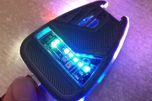
The guitar used was a junk no-name electric. I hollowed out from the front of the body with an oscillating multi-tool and a wood blade, leaving space for the FSRs. Because the body is plywood, it was pretty easy to remove the bulk of the material. I spray-painted everything black and carpeted the inside with adhesive Velcro strips (loop side). This has been quite helpful for cable management and general experimentation. Just put some hook Velcro to the bottom of a breadboard and stick it in there. Need a USB Hub? Raspberry Pi? Velcro!

The FSRs are attached with some double sided foam tape which holds them solidly in place and gives them a little bit of padding, which is good when you are banging on them with your knuckles. The little thumb joystick is mounted in the body with hot glue, and wired through a hole bored into the body cavity. The joystick is meant to be moved with the palm of your hand, allowing you to modulate parameters while tapping on the FSRs... In practice, little thumb joysticks like that are junk, they have too little travel to introduce any decent dynamic. I am actively looking for an alternative, larger joystick with more travel.

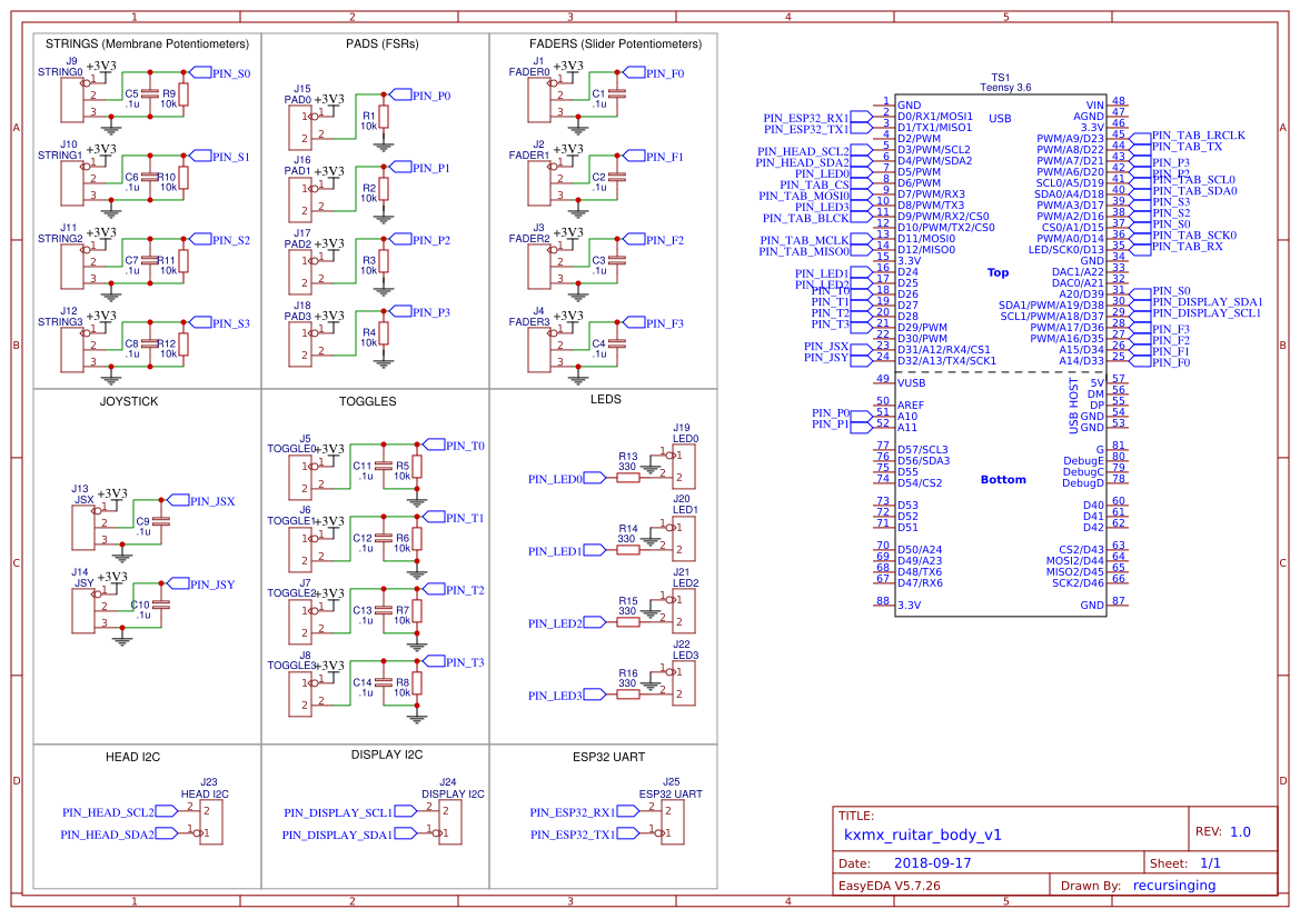
The first prototype was done using breadboards and an Arduino Mega2650 clone. When it was finally functional, I found the latency to be unacceptable, the breadboard connections were fragile and problematic,and I also found it lacking interface components. So, I swapped the Mega2650 for a Teensy 3.6, soldered all the connections using some protoboard, and added the four faders plus four LED buttons. The result is this new prototype module. I'm designing a PCB which will replace this.

There are USB-A and RJ-45 jacks to the side using some nice, locking Neutrik jacks. Because the Teensy's advanced USB capabilities, there is only USB IO at the moment. The unused RJ-45 is for some future ideas.

There is an SSD1306 64x32 OLED display mounted to the side of the body of the guitar. I simply flattened a little part of the edge with a belt sander, and drilled a hole into...
Read more »
 Xasin
Xasin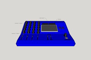
 Daniel Frausto
 Kenneth Marut
 stupid