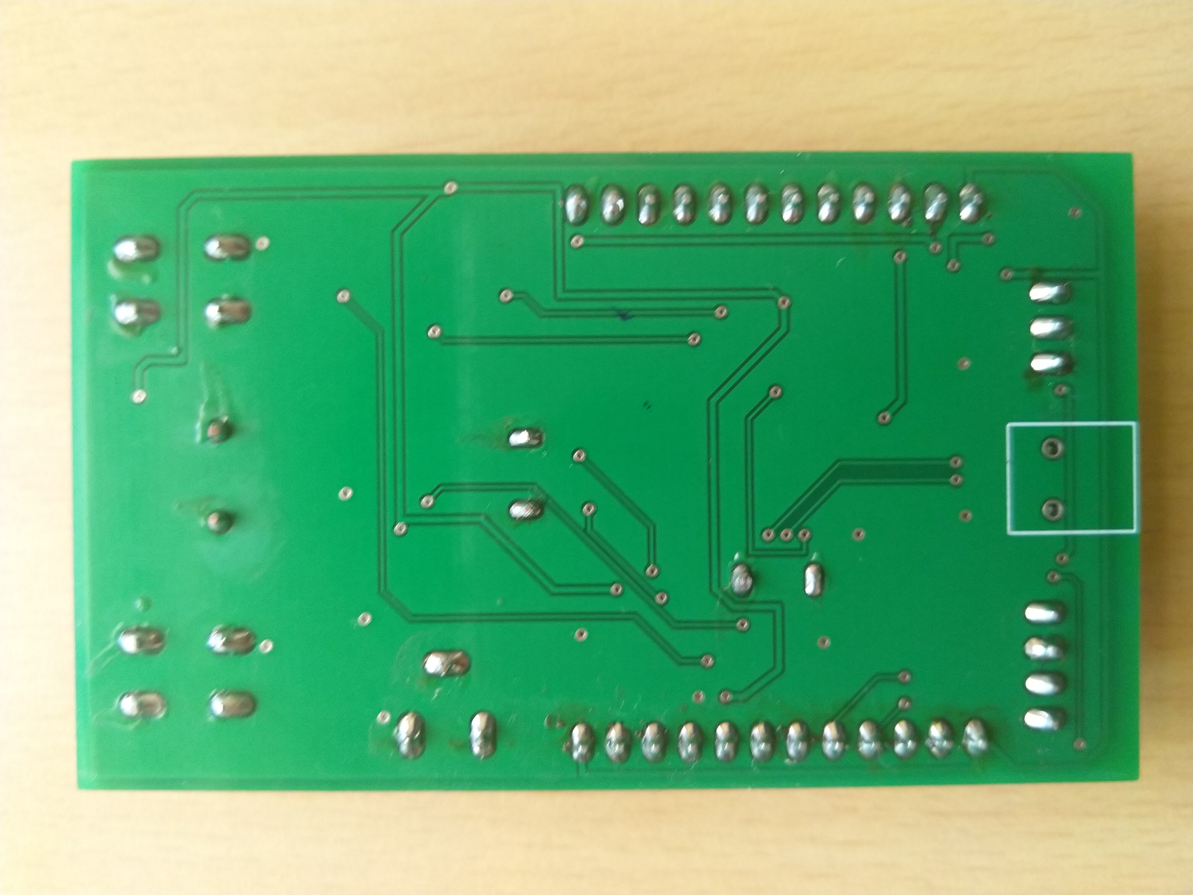
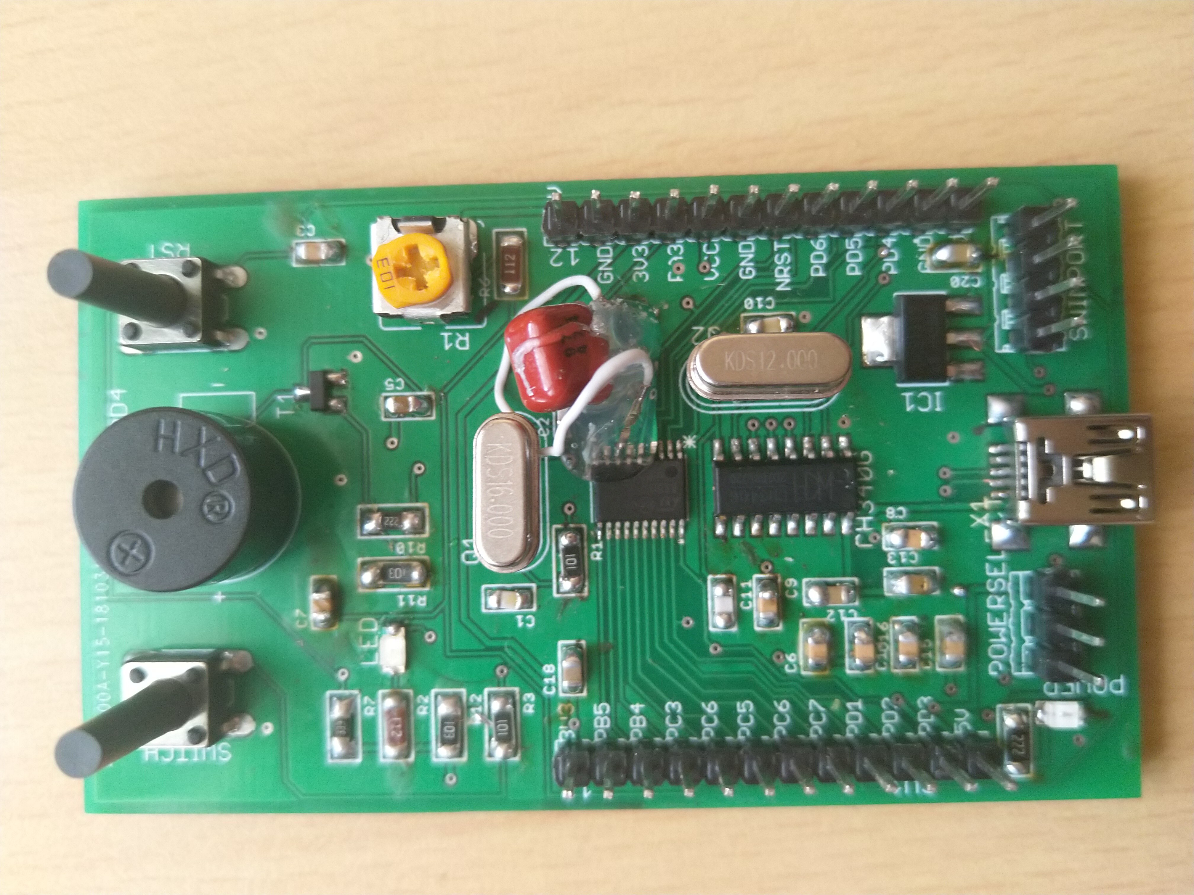
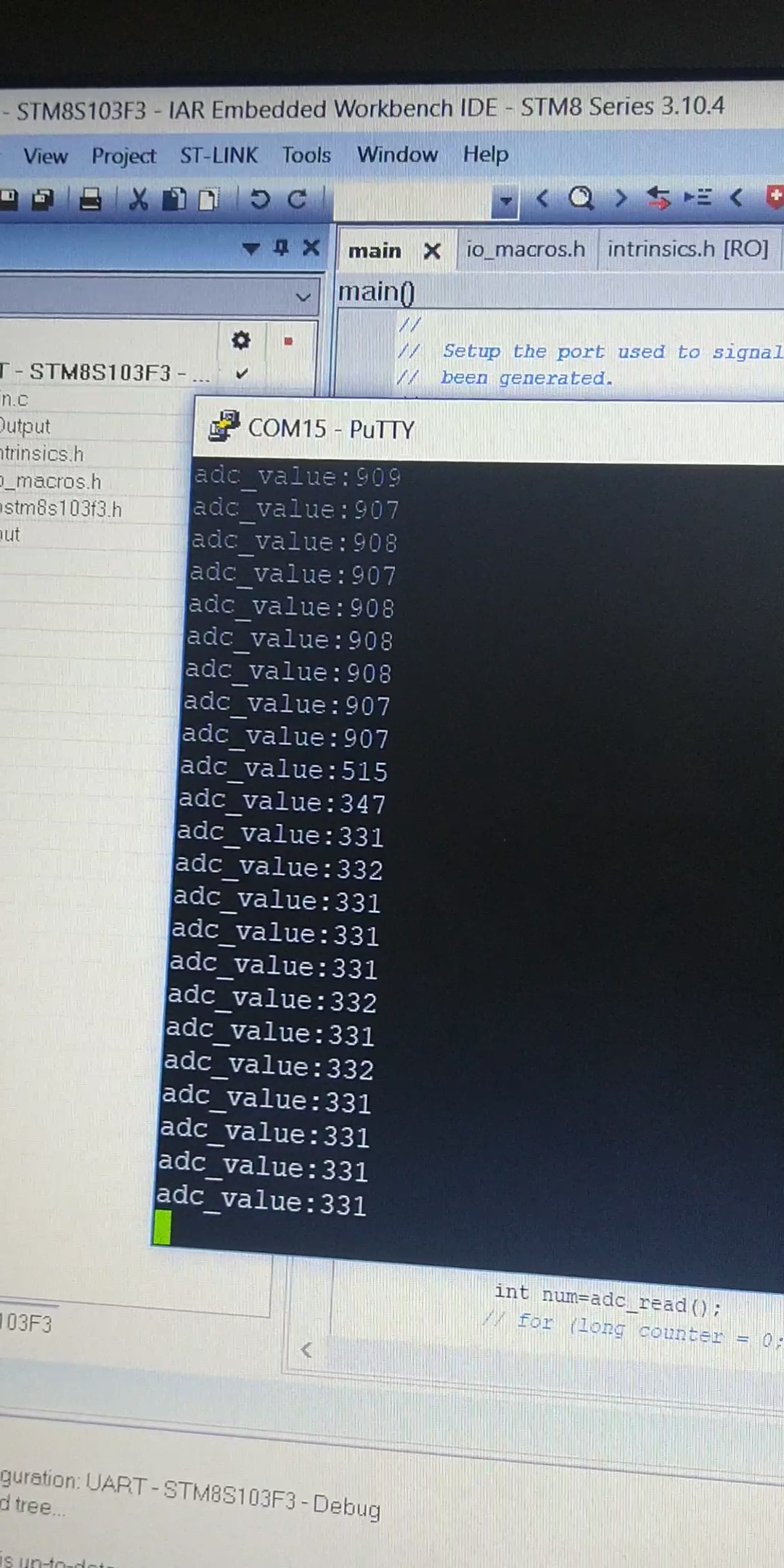
The STM8S003F3 microcontroller development board is designed primarily for general purpose applications. The microcontroller features 16 GPIO pins all of which can be accessed easily by the user through the male header pins provided along the sides of the board. Separate header pins are provided for programming the board through ST-Link programmer as well as for switching the operating voltage between 5V and 3.3V. The board can be powered up through USB cable as well as through the ST-Link programmer. The on-board 3.3V voltage regulator has a current capacity of 800mA and can power up the board as well as interfaced external peripherals. The Type-B mini USB port along with USB to Serial chip (CH340G) provides communication with PC.
Features of the development board:
- STM8S003F3P6 microcontroller.
- On-board 16MHz crystal oscillator
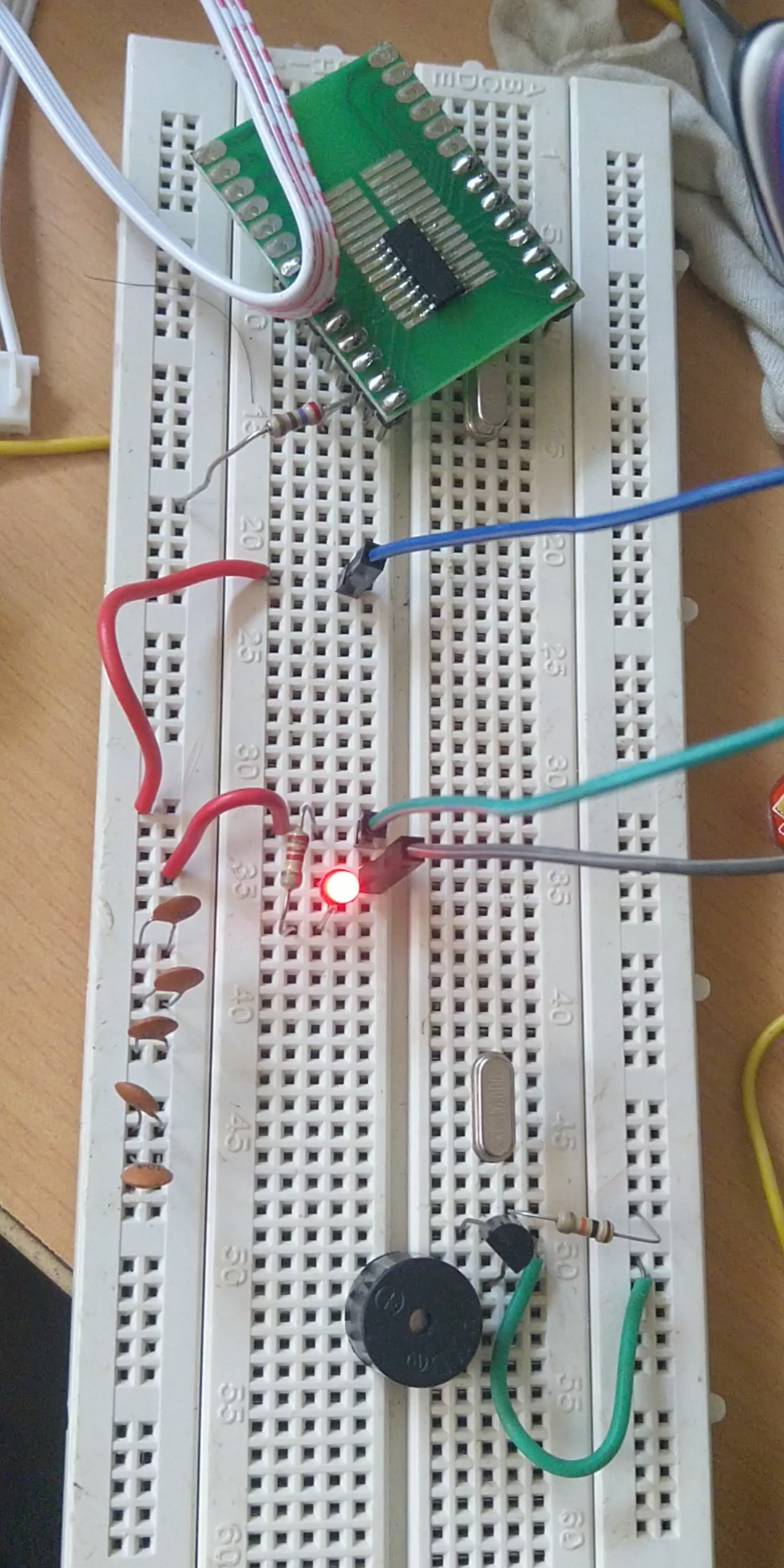
- A Buzzer interface
- One switch
- One reset button
- One user LED
- A 10kohm potentiometer for ADC interface
- USB Type-B mini port for powering up as well as for data transfer
- On-board 3.3V voltage regulator - LM1117
- On-board USB to serial chip CH340G for communication via UART
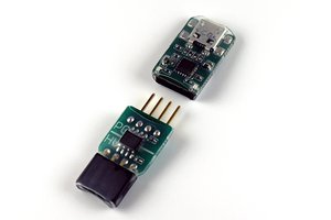
- A 4 pin SWIM port for programming via ST-LINK programmer
- On-board power selector pins for switching the operating voltage between 5V/3.3V
- On-board power indicator LED
- All port pins available through male header strips
- Highly compact with dimensions of 4.53 cm x 7.6 cm
 Saimon
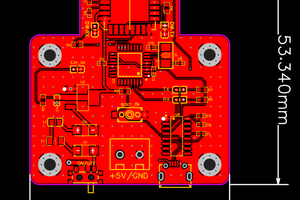
 Omaraittaara
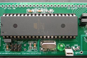
 Bruce Land
 ScarsFun