Jiří Praus
High voltage circuit
Safety warning: You are working with voltages greater than 50V. Contact with high voltage may result in severe injury or death.
Since I am using a regular light bulb which is powered from AC mains voltage I cannot directly use microcontroller to control the power going to the light bulb. I need a TRIAC. This little device acts as a relay that can switch on and off pretty quickly. The microcontroller will power on and off the triac in order to alter the AC sine wave, thus dimming or brightening the light.
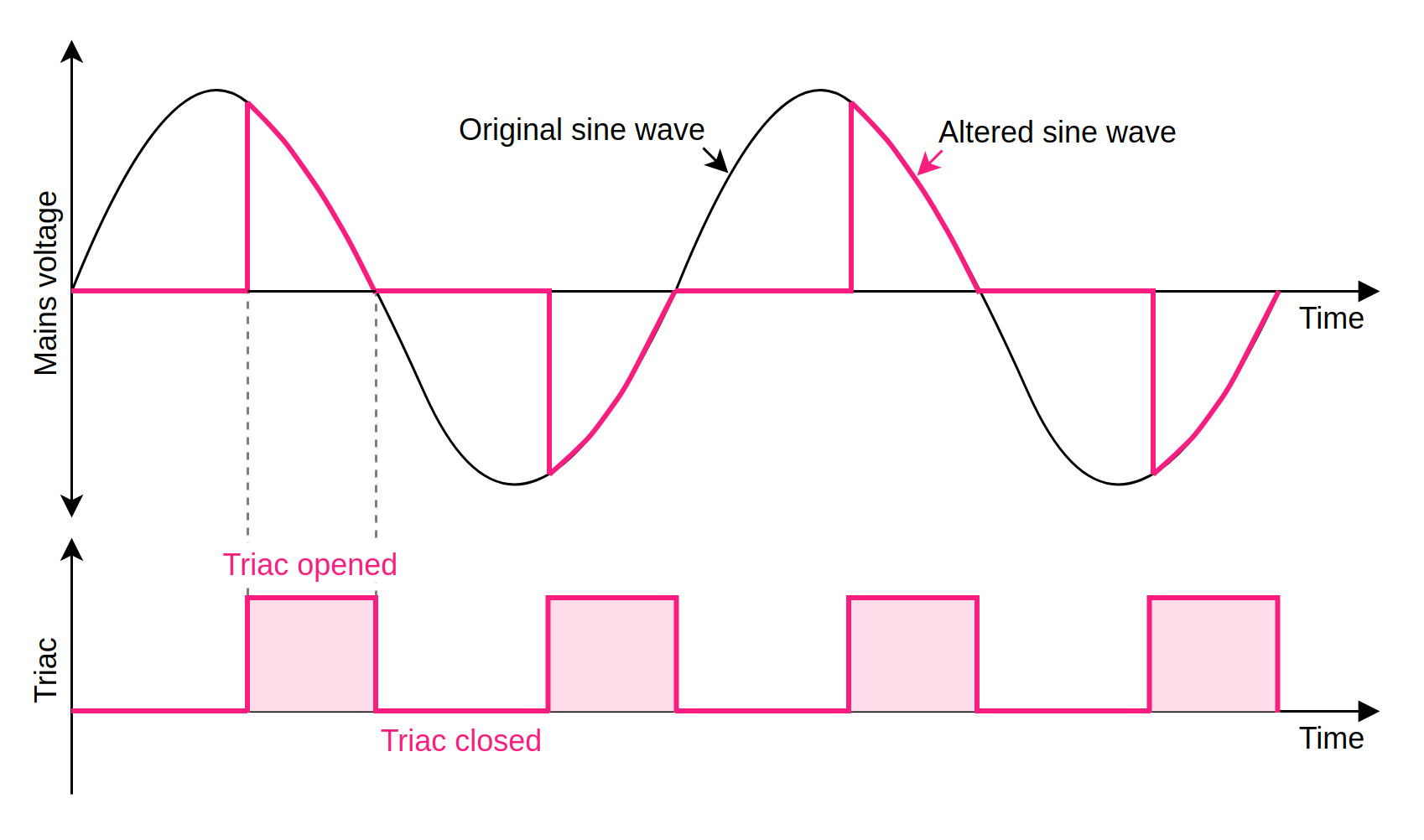
However, AC voltage is controlled differently than DC voltage. AC sine wave needs to be cut in precise manners and so triac have to be turned on and off in precise moments to achieve that (see image below). In other words, microcontroller needs to know when the sine wave of mains voltage crosses zero to cut each of the half waves to the same size. Otherwise, the light would be flickering.
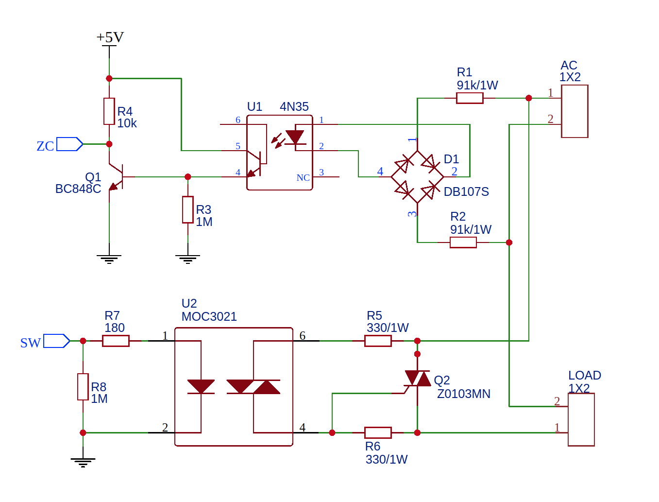
To detect zero crossing of mains voltage there is a 4N35 (U1) optocoupler with a transistor which turns on when sine wave crosses zero. The microcontroller will see that as a high signal on its input pin. Optocoupler has another function, it is to isolate the low voltage from the mains voltage circuit.
Second optocoupler - MOC3063 (U2) - with a triac on output is used to isolate microcontroller from high voltage triac (Q2). Make sure you are not using optocoupler with zero-cross feature because it only switches on when sine wave crosses zero.
Low voltage circuit
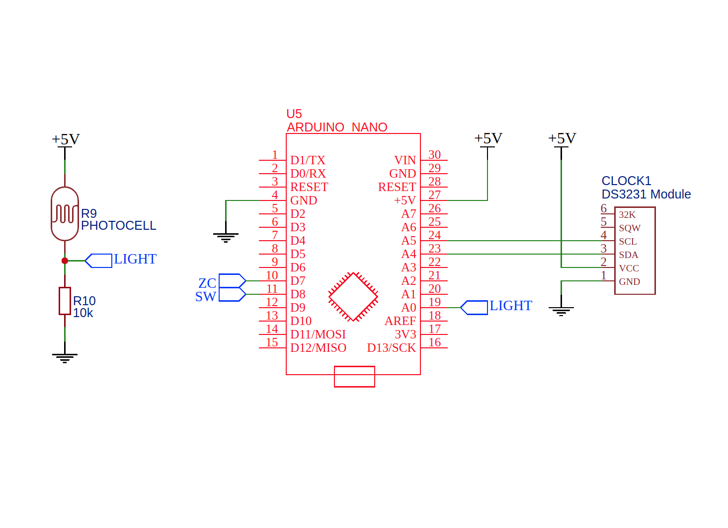
As a microcontroller, I am using Arduino Nano. Its main purpose is to control triac and to start turning on the light when the set time comes. To provide real-time clock there is DS3231 accurate real time clock module which also preserves time when power is lost.
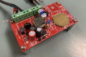
To provider 5V for chips, I am using cheap 5V 700mA step-down power supply connected to mains voltage from bulb socket. Nice and handy solution!
Code
The program is pretty simple. When the lamp is powered up by the switch it will light up the room an slowly dim it into the night as a verification that electronics still work. During the night it checks the real-time clock stored in the DS3231 module and finally at 6 am the room is slowly light up to full "daylight" until the lamp is powered off by the switch.
Check out the code attached below I think its self-explanatory. If it's not I am a bad developer!
What's next?
Now I will experiment for a few days or weeks and if it can wake me up in the morning I will evolve this project into something more smarter and less crude!
Good night!

 Jan Waclawek
 Morning.Star
 Zalmotek