-
Quantifying performance for the bigger 14-LED ring
11/30/2018 at 20:11 • 0 commentsSeeing images reconstructed from the new, larger ring was pretty cool. But did it offer improvements besides making pretty pictures? In this test, I try to quantify that.
First, some background. With the first ring of sensors I built (8 LEDs, 8 PTs) I used my 3D printer to position an object in 500 random, known locations and take readings for each. I split this data into two sets - one for testing (125 samples) and one for training (375 samples). I train a regression model to predict the location based on the readings. For the 8-sensor ring (r8 from now on), the best model I can make has a mean absolute error (MEA) of 2.3mm, with a root mean squared error (RMSE) of 2.8mm. Shifting to the offset r14 arrangement described in the previous project log, the MEA drops to 1.2mm, RMSE of 1.6. A marked improvement. To put it in plain language, you could place the pen within the ring and have the model tell it's location to within 2 mm most of the time. There are a couple of outliers, but for the most part the model is surprisingly accurate.
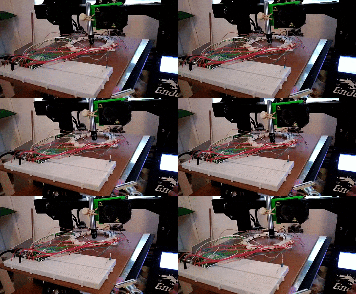
I wish I had time for more details, but for now here's the data collection process. Move to location, record data, repeat:
![]()
Salient points:
- I used the same 500 positions for the two arrangements
- Moving from 8 to 14 sensors reduced the RMSE of predicted locations by ~40%, not bad!
- For the interested, the machine learning model is a Random Forest regressor from scikit-learn
- Getting the training data is time consuming, even when assisted by a motion platform like a 3D printer. More on this point to follow.
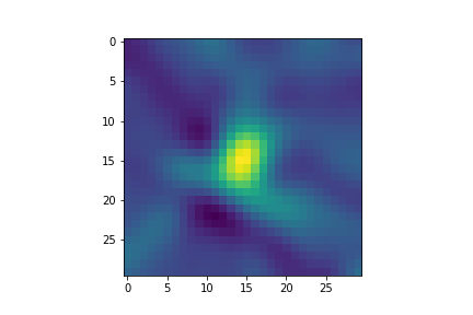
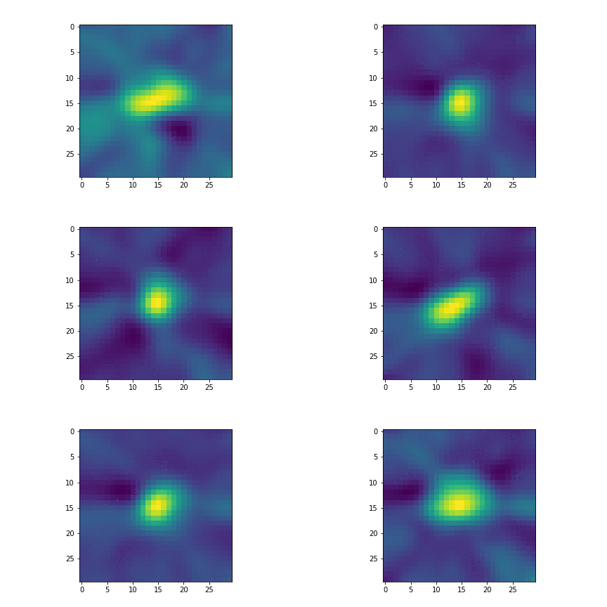
Doing image reconstruction on one set of readings:
![]()
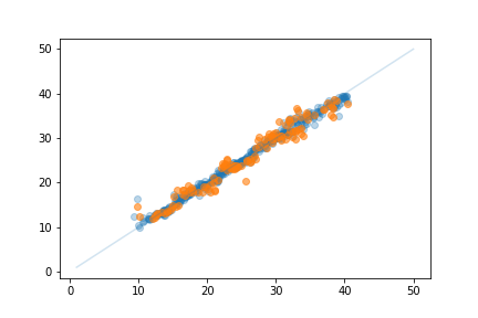
Plotting predicted X location vs actual location for training (blue) and test (orange) data. Not bad!
![]()
With this, I can now take a set of readings and predict the location of an object within the ring. Useful? Maybe. Fun? Yes.
-
Break time is over - a bigger, better sensor ring
11/16/2018 at 13:11 • 0 commentsI took a bit of a break once the project report was submitted, but I was itching to carry on testing some ideas I'd had which were a little beyond the scope of a one semester project. This weekend, I finally got back in the workshop and built a better sensor ring. I had previously tried to build a ring with 16 sensors, but had used the wrong ones and made some other mistakes.
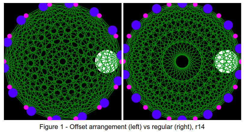
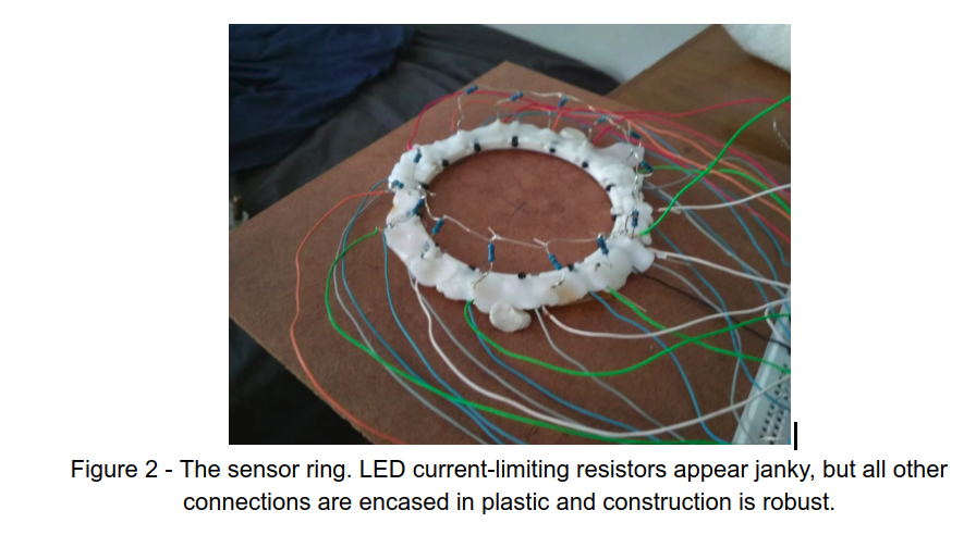
I didn’t have quite enough of the more sensitive phototransistors left to make another ring of 16, so I decided to try something different: A ring with 14 LEDs and 14 PTs in a non-symmetric arrangement. The arrangement is shown on the left - note the difference between this and the one on the right (regular spacing). That hole in the centre has been bugging me.
![]()
The ring is built better than the previous ones. The LEDs are connected to 5V (not the 3.3V of the GPIOs) and pulled low when activated. This means the signal received by PTs on the other side of the circle now results in adc reads from ~200-900 (out of 1024) giving a much better range than before. The beam spread is still an issue - only about 5-7 PTs opposite the LED are illuminated. But this is still enough to do some image reconstruction!
![]()
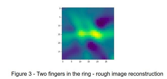
I am busy with the maths (see next bit) but by interpolating to approximate a fan-flat geometry I can already get some images from this thing. Figure 3 shows one example - the two separate blobs are two of my fingers, inserted into the ring. Reconstructions get worse away from the center as less light is available (beam angle) and so the signal is smaller. But there is a nice central area where it works well.
![]()
One cool aspect: this ring can capture scans at >100Hz, although my reconstruction code can’t keep up with that. I can store data and reconstruct later to get 100fps ‘video’ of objects moving around. For example, I stuck some putty onto a bolt and chucked it into a drill. Here it is as a gif:
![]()
I've only just started playing with this, but should have a bit more time to try things out in the coming week (here's hoping).
The maths
At the moment, I use interpolation to get a new set of readings that match what would be seen by a fan beam geometry with a flat line of sensors. This means I can use existing CT reconstruction algorithms like Filtered Backprojection (FBP) but by doing this I sacrifice some detail. I'm hoping to get some time to work out the maths properly and do a better job reconstructing the image. This will also let me make some fairer comparisons between the two geometries I'm testing (offset and geometric). It will take time, but I'll get there!
For now, enjoy das blinkenlights
CIRTS - Configurable Infra-Red Tomography systems
Using cheap IR LEDs and phototransistors to understand tomography. Using machine learning to make inferences based on sensor data. Etc :)
 johnowhitaker