 Ben Lim
This project was a result of too much time spent making almost identical breakout boards for SMT chips each time I wanted to test a new chip, and I test a lot of new chips, so you can imagine that's a lot of time wasted designing and manufacturing new boards.
I built this board because I have not seen another board do this, and I wanted it for my own prototyping purposes. It relies on the fact that there is a standard package size for different types of microcontrollers and sensors
This reduces the waste and messiness from having wires and capacitors all over the breadboard, and it allows you to easily deploy or remove this breakout whenever you want. You simply don't have to redo the entire process each time you want to prototype something new.
Finally, I think the best part of this board is that it is reusable across different chips that have the same footprint because it is generic. The simple hardware select that I designed can be used for other types of ICs as well: think voltage regulators, sensor packages... etc.
I have designed boards of various sizes and I have used them extensively in prototyping.
Detail
I looked at what these boards had in common and distilled it into a single board.
It turns out that for most basic implementations, you need four configurations for each pin:
- Ground
- Power (with a capacitor filter)
- Pull-up
- Pull-down
Therefore, I designed a hardware select for each pin. and integrated it into a form factor that can fit on a breadboard. The description of how the hardware select works is in the project logs.
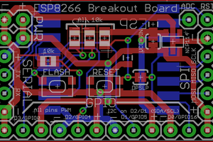
The Essentials Breakout Board provides the option to pull up/pull down/power/ground each pin. Additionally, you can also provide filtered power to each pin.
There is space for clocks so that you can connect external clocks to the mounted IC. Since it is not very predictable which pins will connect to the clock, I use wires (not ideal but it works!)
The board was made to fit onto a breadboard for easy prototyping.
The ground and power lines are consolidated into one single pin, therefore, in order for you to breadboard a SMT chip with this board, all you need to do is to connect power and ground a single pin and you would have a completely functioning circuit.
Limitations
This board is mostly suited for MCUs as well as other types of ICs. It will probably not perform well if used with a wireless IC as it does not have room to incorporate an antenna.
 Sukasa
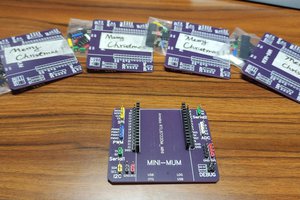
 SimonXi
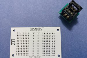
 Bits4Bots
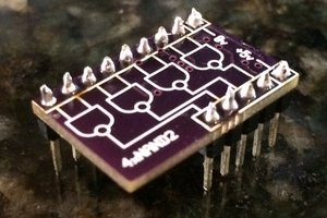
 SHAOS
SHAOS