High Level Design
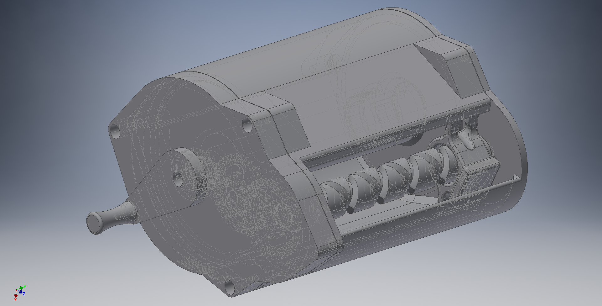
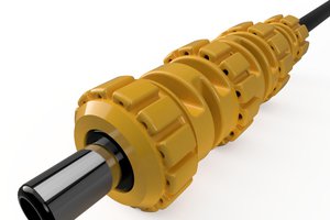
I designed the reel in Autodesk Inventor. This is a screenshot from the assembly:
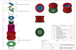
And the exploded view:
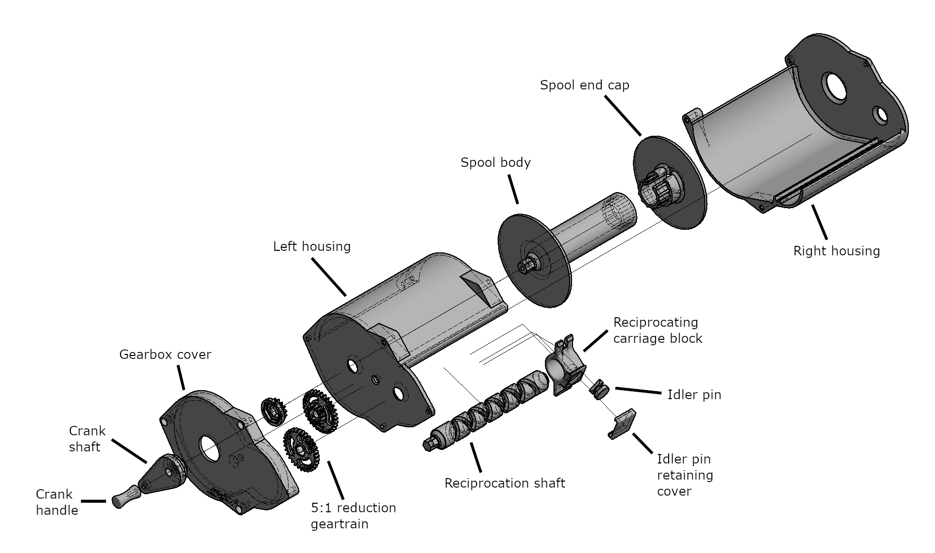
The crank drives the smallest of a set of three gears, which is in-line with the spool body (the spool body and the crank turn together). The 3 gears constitute a 5:1 reduction driving the reciprocation shaft (reciprocation shaft turns once for every 5 turns of the spool). The reciprocation shaft has a shallow crossback thread, within which the idler pin rides. The thread makes 5 turns in each direction, so after 10 complete revolutions of the reciprocation shaft, the carriage has made one complete trip from one end to the other and back. This makes ~25 wraps per layer, which is very close to the nominal (the cable is roughly 4mm in diameter, and the spool's internal width is 96mm). The spool itself is sized so as to leave enough room for the total number of neat layers needed to store the cable plus a factor of safety.
The spool disassembles into a body and an end cap. The end cap has a small slot which allows the spool end of the cable to be passed through the bore of the spool and out the hole in the right housing. When setting up the Vive, the free end is pulled out of the spool until the desired length is reached, and then plugged in. The spool end can then be untucked from within the bore of the spool and plugged into the other lighthouse.
3D Printing Considerations
The entire spool, excepting the spool body and end cap, can be printed without supports. I achieved this by partitioning the design into a set of planar features with all extrusions starting from the build plate. All mating surfaces are toleranced to between 0.2-0.5mm of gap, so as to allow smooth sliding, rotating, and meshing. The crank handle is printed in TPU, whereas the rest of the parts are printed in PLA.
Reciprocation Shaft
By far the trickiest part of this design to print successfully was the reciprocation shaft. This part requires extremely high surface quality to guide the idler pin without binding. My first attempt at printing the part was on a stock Monoprice Select Mini, which had insufficient cooling to achieve the required surface quality on the overhung thread ways:
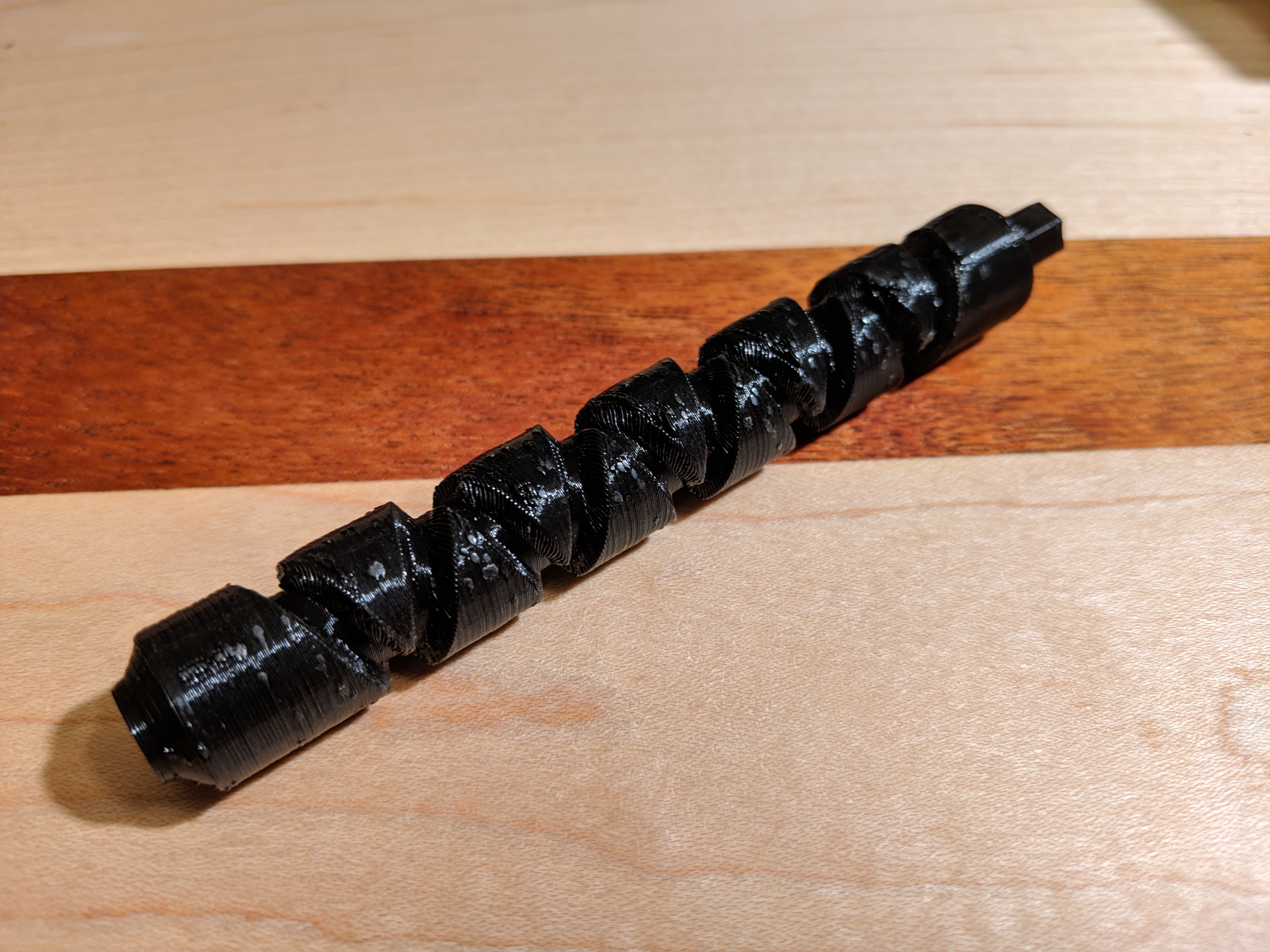
(Notice the many surface blemishes and defects.)
After switching over to my Anet A8 and upgrading the stock fan shroud to a custom ring manifold, I was able to get the extrusion product to cool fast enough to stop warping.
Idler Pin
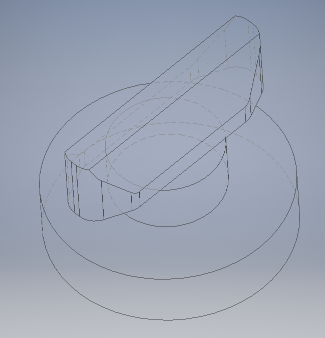
The idler pin presented the next set of challenges. I had to determine the correct set of surface drafts, chamfers, and rounds to get the tooth to ride smoothly in the thread on the reciprocation shaft. I initially tried a simple wedge shape with no extra surface modifications. This proofed the concept, but it was far too sticky to put into the final implementation. I iterated several times, finally settling on a shape reminiscent of a rice grain:
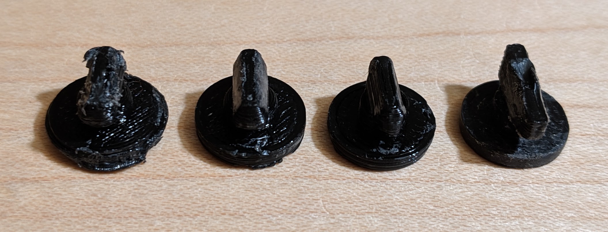
(The good, the bad, and the ugly. Leftmost: this one was too fat, and got chewed up pretty badly by the reciprocation shaft when I was testing the mechanism. The circular plate at the bottom was also too large, so I had to use a screwdriver to pry it out of the carriage block, further ruining the part. Left center: This one was also too fat. I had a go at filing the surfaces down manually to get it to fit, and this got me pretty close to the final design. Right center: This one was too short. It wouldn't bridge the crossover points on the reciprocation shaft, and so would bind up and sometimes even derail or spontaneously switch directions while the mechanism operated. Right: This part was too long and too tall. I don't quite remember how that groove got melted into the top of the tooth, but I would suspect overzealous cranking *cranking intensifies*)
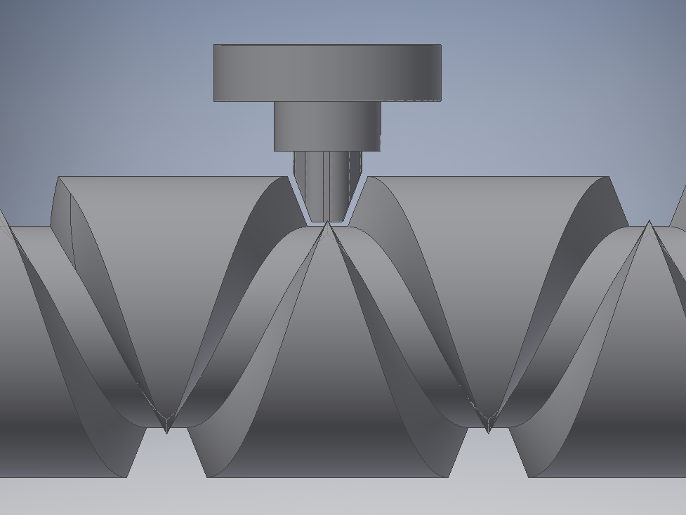
The rounds on the leading and trailing edge of the pin allow it to turn around at the bottom of the reciprocation shaft thread, and the drafted faces match the V-shape of the thread:


 Daren Schwenke
 Sam Ferguson
 Alex Rich
 Johannes Hassler
awesomely useful project!