 Grant Giesbrecht
I began by running a few dozen simulations using the same code I developed when designing the low band. I was looking for a frequency response which would not overlap too much with the low band (or later, the high band) and which would be centered close to where voices tend to reside. This way the mid band of the equalizer is able to adjust the volume of voices in the sampled audio. Nothing I saw in the simulations was satisfactory. It predicted a low Q factor and low maximum gain. I tested one of the simulations' circuits on a breadboard and got a result which conflicted with my simulation. I believe that the issue is that the circuit's transfer function is strongly affected by the op amps's input bias current, which I modeled to be zero in my simulation. I decided to switch over to experimental guess & check methods briefly to see if I could find a solution that way or if I'd need to revise my model and proceed with simulations. To get very quick experimental data I used my waveform generator's sweep functionality to feed the test circuit sine waves between 10 Hz and 20KHz over the course of about 5 seconds. Setting my scope to single trigger at the start of a sweep made my scope display what was effectively a crude bode plot. I used this system to quickly try different circuit designs until I achieved a frequency response approximately equal to what I was looking for, at which point I switched back to the more tedious but also more precious system of measuring gains and various discrete frequencies manually.
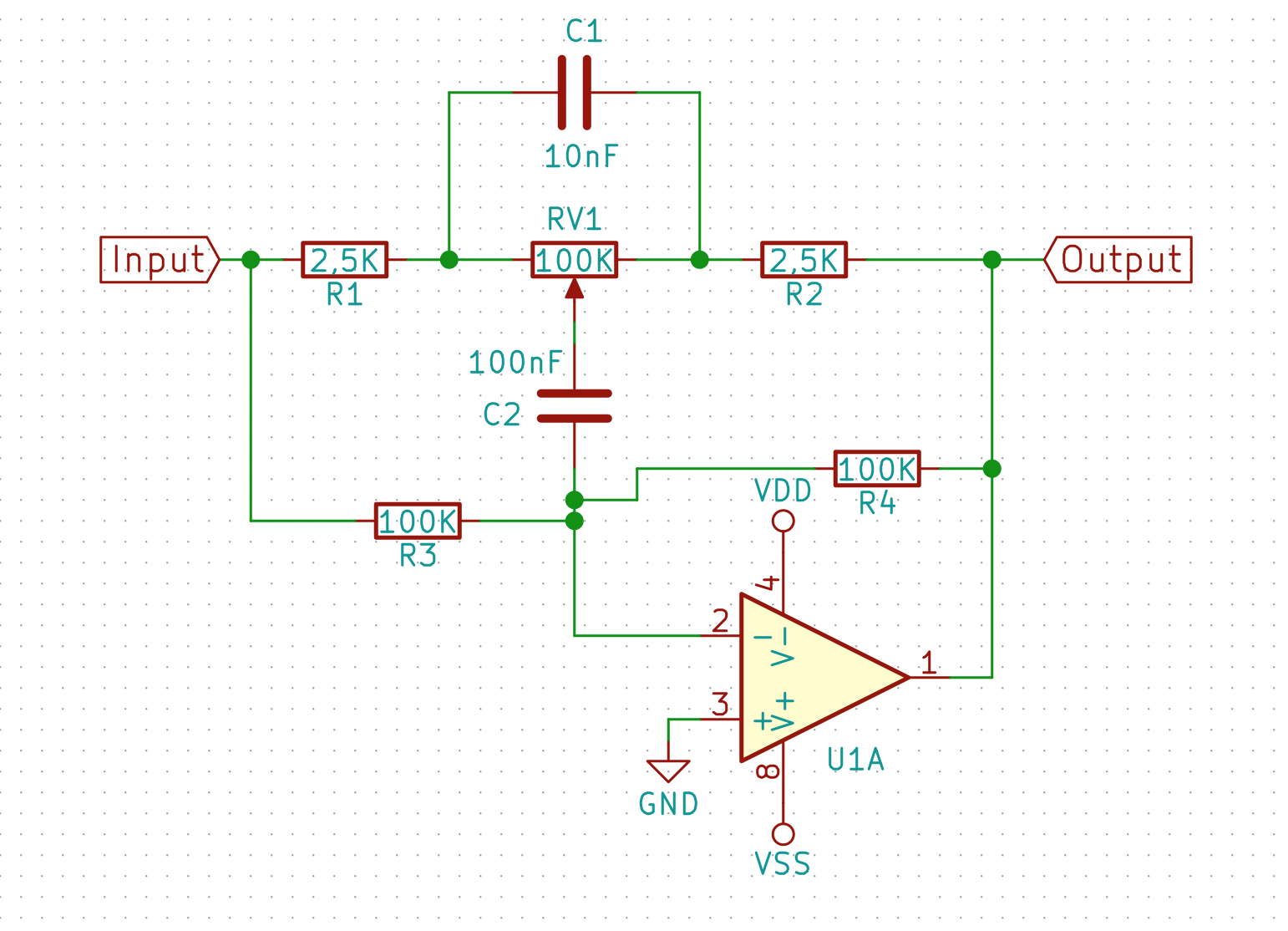
Eventually I settled upon the design shown above for the mid band filter. It has a much higher Q and gain than my previous equalizer's mid band.
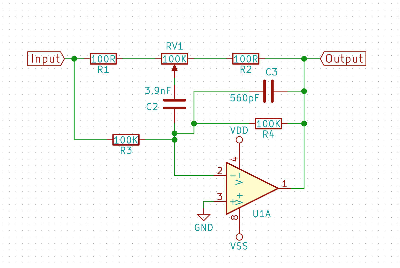
The high band was pretty quick to design using the experimental guess and check method with swept-frequency sine waves to generate bode plots. I found a few designs that seemed feasible and tested them by listening to audio signals through them. Ultimately I decided upon the design shown below.
Discussions
Become a Hackaday.io Member
Create an account to leave a comment. Already have an account? Log In.