Close
0%
0%

Water Alert

hear it before you step in it

Similar projects worth following
This is a project that I originally did a a few years back. The original works well but I'm planning on building a more compact version that's designed to be battery powered as in some places there aren't any nearby outlets.

Some backstory: After a washer decided to leak all over the floor and a water heater decided to leak and create another nice mess, I decided to make my own alarm to detect when a leak occurs. It's not a fun experience when you notice that a towel sitting in a closet next to the water heater room is mysteriously wet.

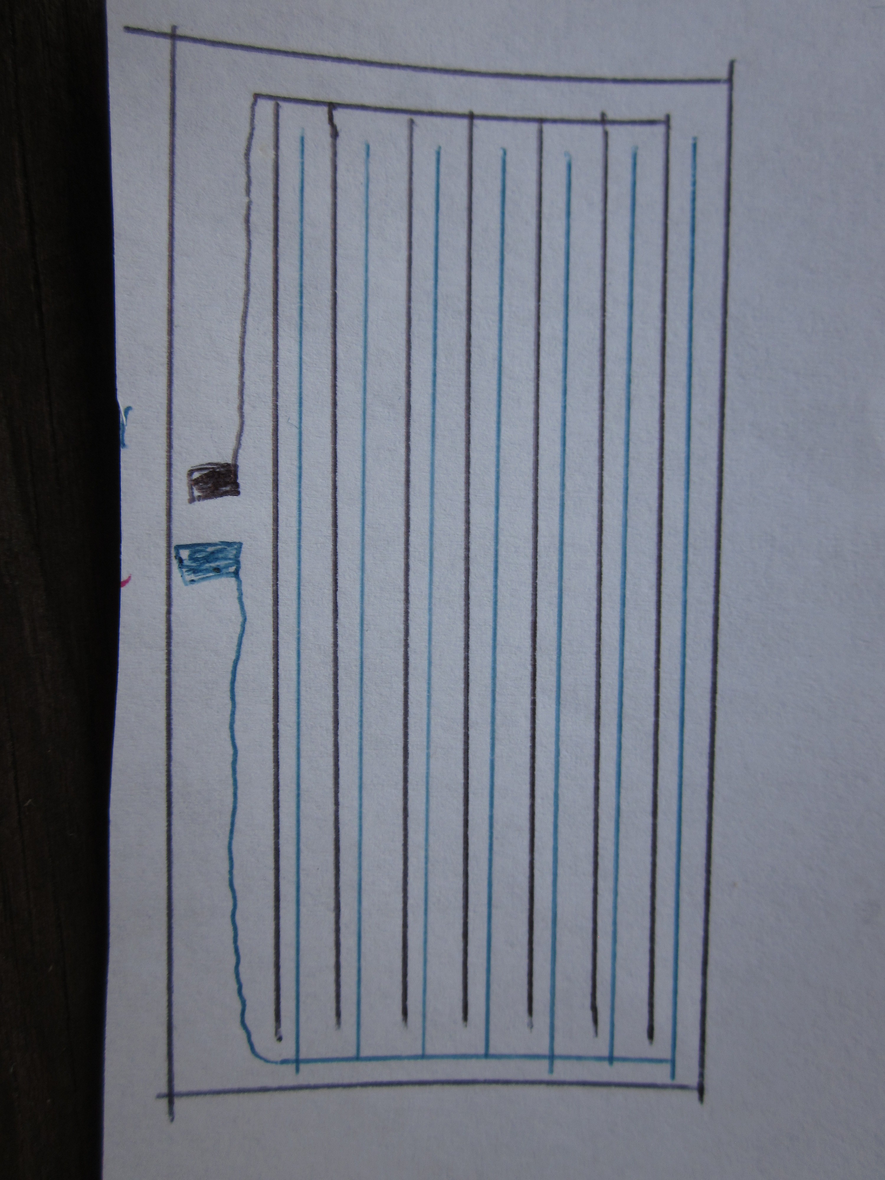
I've learned a few things from the original project.  The most important how to set up to leads to be most effective.  If something such as a water heater sits on a metal drain pan, it makes sense to attach one of the leads to it, and thus make the drain pain an electrode.  Using something such like an aluminium shell of a tealight candle can be used for the other electrode and the two can be separated by a piece of paper towel as shown in the photo below.

If one isn't lucky enough to have something in the environment to serve as an electrode one could use something such as a piece of aluminum foil placed flat on the floor, a piece of paper towel, and the other electrode on top.

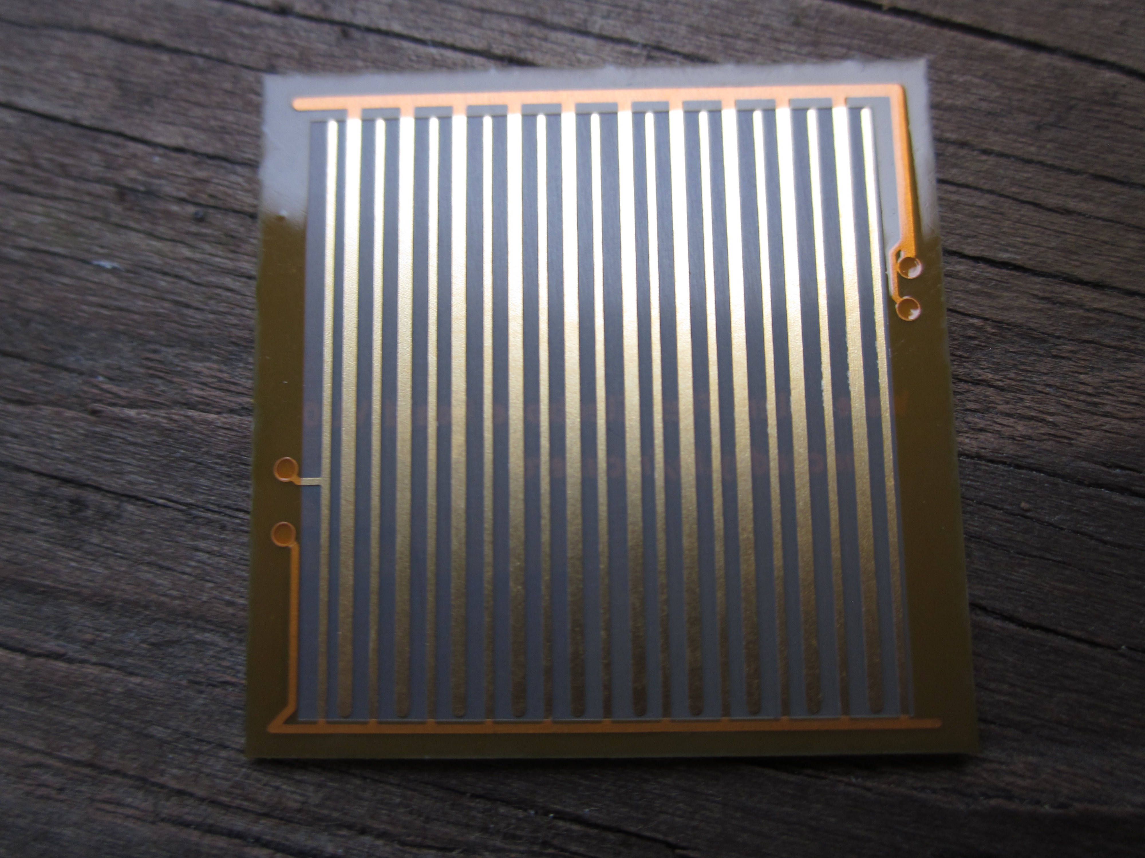
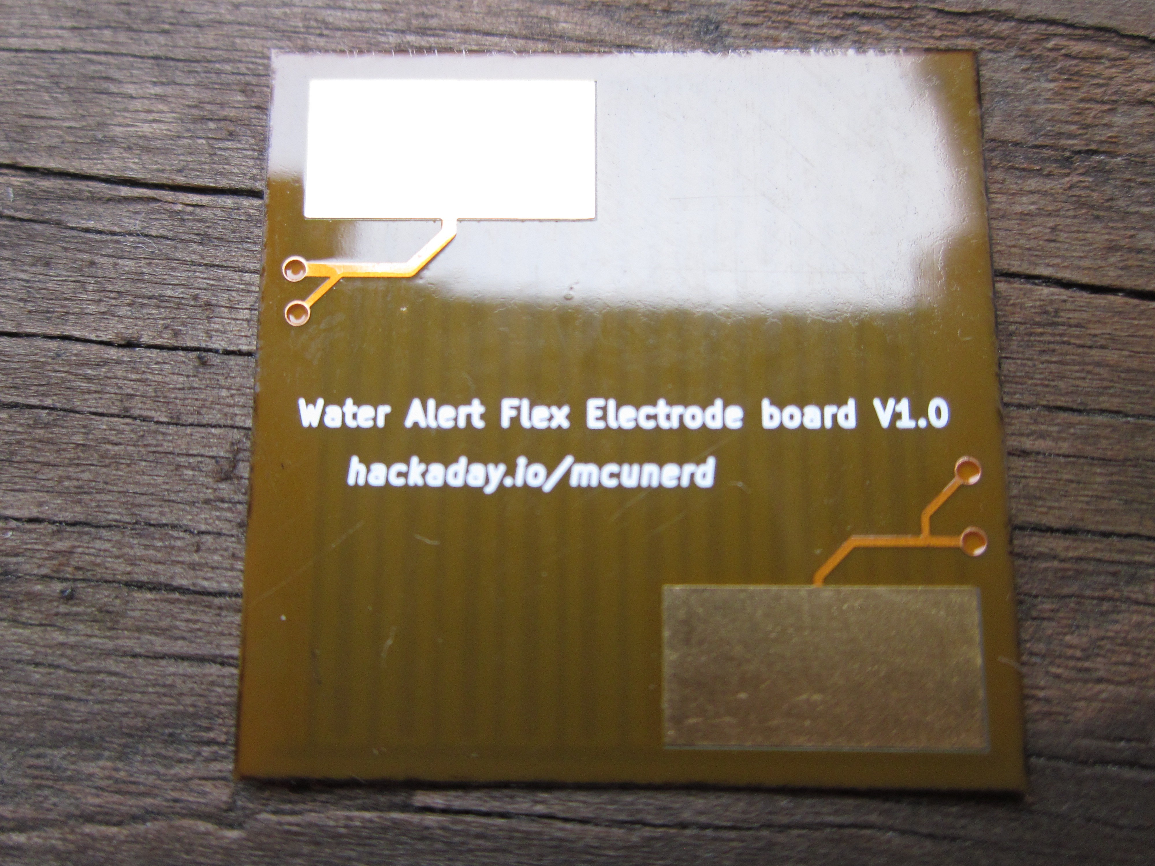
Flexible PCB concept is located on this project log entry page:

https://hackaday.io/project/164512-water-alert/log/163404-flexible-pcb-contest-entry

water_alert_flex_electrodes.zip

electrode flex PCB KiCad files

x-zip-compressed - 25.55 kB - 11/20/2019 at 21:14

Download

water_alert1.1.zip

updates water alert KiCad files with the corrected resistor placement

x-zip-compressed - 94.85 kB - 11/20/2019 at 21:12

Download

t85water.zip

original water alert Attiny85 code

x-zip-compressed - 8.25 kB - 03/22/2019 at 13:48

Download

water_sens.zip

original water alert KiCad files

x-zip-compressed - 78.46 kB - 03/22/2019 at 13:46

Download

  • Sensitivy is great using a 2M ohm pull-up resistor

    mcu_nerd10/22/2022 at 21:59 0 comments

    I finally did take the opportunity to swap the pull-up resistor. I didn't have any 1M ohm resistors in 0805 size at the time, but I did have some 2M ohm resistors.  The weaker pull-up made all the difference.

  • As I promised last week

    mcu_nerd11/20/2019 at 21:15 0 comments

    I finally got the the time to assemble the new version and tried out the electrode flex PCB.  I've posted the KiCad files for both on the project page.I did have to increase the value of the pull-up resistor a bit on the input pin, currently using a 200k pull up.  The flex PCB is still a little bit on the insensitive side, so I might bump it up to 1M ohm.

  • Well it happened again.

    mcu_nerd11/14/2019 at 20:55 0 comments

    Yet another one of my projects ended up a focus of a HaD article, which works well as a motivational tool to get back on working on a project that's been pushed on the back burner.  I'm happy to say that I have had a newer revision of the PCB made with the resistor placed across the buzzer as opposed to in series with it.  I need to assemble it, then I'll post the KiCad files and Gerbers, and actual photos.  I also need to try out the  electrode flex PCB and post those files. 

    I'll be a bit busy for the remainder of this week, but I should be able to get around to the above tasks next week.  I also wish I had a dedicated work area for my soldering station, hot air station, etc.  Setting up shop in the kitchen is problem when others want to use the kitchen for it's original purpose.

  • Putting it all together

    mcu_nerd06/22/2019 at 13:59 0 comments

    I first worked on things individually such as the alarm siren, checking battery voltage, and detecting the presence of water.  I'm now working on combining it all into the finished firmware.  It's mostly completed but I'll be adding a few more tweaks such as staying in low power mode for much longer and having a low battery alarm (right now the indicator LED just long blinks when the battery voltage is low.)

    The features it includes/will include:

    Sounding an Alarm when water is detected

    Every so often measuring it's own voltage without the use of any I/O pins

    If low battery voltage is detected sound a different brief alarm (to be added soon)

    Every so often briefly flash the indicator LED to show that it's still operating

    A key goal I've been working to achieve as best as possible is to keep the Attiny85 in extremely low power down sleep mode for as much of the time as possible.  In power down mode, both INT0(which I'm using for water detection) /pin change interrupts and the watchdog timer interrupts still work.  I could dump the idea of both indication that it's still operating and low battery detection and get a theoretically long battery life of around 33 years using two AA NiMH cells rated at 1350mAH (measured current at power down mode was 4.7uA.) Of course the limiting factor would likely then be the self-discharge of the cells.  I may release a firmware without the "it's still working" and low voltage checks.

    I thought hard about sticking a CR2032 holder on the board but decided against it.  There doesn't seem to be anything standard in terms of a PCB footprint for a CR2032 holder.  So if I did that, I would likely have to stick to a particular part number and others that would want to make their own would have to go hunt it down. Wouldn't be a big issue if I was planning to make them in mass, but since I only plan to make a few it didn't make much sense to me.

    In related news, I won a voucher from the HaD flexible PCB contest, so It looks like I'll be taking a crack at designing aflex PCB to serve as the water sending electrodes.

  • Flexible PCB contest entry

    mcu_nerd05/14/2019 at 14:13 0 comments

    Thought I would take a shot at it since the contest states there will be 60 winners and there's only 41 entries currently(well 42 after I submit this entry.)

    I was thinking that a flexible PCB would be nice to use for the electrodes.  The idea is fairly simple: simply have two sets of exposed traces run close to each other and have a set of pads for soldering the wires that run to the Water Alert board. The PCB could then be simply taped to the floor or another surface that needs to be monitored. I did a simple sketch of it(please excuse the very crude drawing.)

  • Piezo buzzer FAIL (and fix)

    mcu_nerd05/10/2019 at 01:35 5 comments

    A few days back I played around with creating a siren sound on the Atmega328P, which I would later port to the Attiny85 and incorporate it in this project.  I simply hooked up a piezo directly to one of the I/O pins (with a series resistor.)  It worked just fine.  

    Yesterday I assembled one of my new Water Alert boards that I got last week. I ported the siren code over the the Attiny85 and plugged the programmed Attiny85 and a piezo into my Water Alert board.

    I heard absolutely nothing.

    I checked my code, found something that needed to be changed and tried again; nothing.  I swapped the piezo for a larger one.  This time I heard it extremely faintly.  Some progress at least.  I then went down the rabbit hole trying to isolate the problem. I went from using a 2xAA battery back to a 3xAA pack; no improvement.  I hooked up the board to a 5V supply; no improvement. Could the issue be the cheapo "Shenzhen special" transistor on the board? I created a breadboard version of the peizo driver circuit and once again, no improvement.

    I decided to try directly driving the piezo from the I/O pin. A considerable improvement occurred. Perhaps the issue was how I was trying to drive it.  I did a bit of googling and found the answer!  Apparently due to the capactive nature of a piezo buzzer, there needs to be a way for it to discharge when when the transistor is turned off.  I naively thought that I could drive it just like an LED.  The fact that it worked by driving it directly from an I/O pin further made me think it wouldn't be an issue.  The easy solution is to put a resistor across the piezo leads. I tested it, and that fixed it. I made a more permanent fix by bodging in a 150 ohm resistor across the piezo header pins on the board (the first time I've ever done an actual bodge on a board I designed.)

    lesson learned: Test out circuits that I have not done before on a breadboard before ginning a board!  This is why I haven't posted the board files yet, in case there was a design issue.  I'll go back into KiCad and make the correction tomorrow.

    I got a bit curious of why it worked fine when the piezo was directly hooked up to an I/O pin.  I remembered that many MCUs such as the Attiny85 and Atmega328P have internal ESD protection diodes, perhaps those diodes were what allowed the piezo to discharge, and thus work.

    I setup my breadboard circuit again.  I tried a normal diode I had lying around, didn't work.  Was I wrong?  I thought about it for a few moments. Those internal ESD production diodes are likely fast switching.  I looked thru the horde and found a schottky diode. I put the diode reverse-biased across the piezo leads and it worked!

  • A creative solution to battery voltage monitoring

    mcu_nerd04/24/2019 at 13:54 0 comments

    I was originally thinking about using the typical voltage divider and ADC with the internal 1.1V reference on the Attiny85 to monitor the battery voltage and sound a warning when it got low.  I wasn't crazy about using a voltage divider as it would always be consuming power.  High value resistors could be used to minimize power consumption but I've read that there are potential issues with feeding the ADC with little current (high impedance) source.  MOSFETs could be used to cut power entirely to the voltage divider when not measuring the voltage but then the part count starts the creep up a bit as well as additional board space needed.

    There had to be a better way I thought.

    I did a bit more googling and stumbled upon this article about monitoring battery voltage with no external components at all! It's simple yet ingenious.  Here's what it essentially boils down to: setting the unknown VCC voltage as the reference and use the internal 1.1V reference as an input.  With some simple Algebra the ADC formula can be written as VCC=(1.1*1024)/ADCvalue.   The chip designers apparently had this use case in mind for many AVR chips including the Attiny85 it permits the internal 1.1V reference to be set as an input.

    Mind blown!

    Anyways Microchip has an article here about doing this.

View all 7 project logs

Enjoy this project?

Share

Discussions

Similar Projects

Does this project spark your interest?

Become a member to follow this project and never miss any updates